Worth adding these tubes?
C10CoryM - 30/11/08 at 12:51 AM
Hey guys,
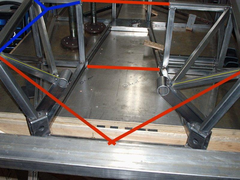
Trying to decide if it is worth adding some more triangulation to my chassis.
Picture is from front of car. It's an old picture so there is other triangulation elsewhere.
The red lines are bolt in tubes that are definitely going in. The ones in questions are the blue tubes (only drawn in on one side). They are pretty
difficult to fit, exhaust is in that area.
I was worried that when my engine is loaded it will pull/push the tubes with the yellow lines enough to flex the upper tubes. I am starting to think
the red tubes in the foreground will be enough though.
Engine produces 300ft/lbs (407Nm) and I intend to use all of it as often as possible.
Input?
Thanks.
Cory


Rescued attachment mounts.JPG
tomgregory2000 - 30/11/08 at 06:45 AM
thats a fair old amount of power, i would but im no expert
Ivan - 30/11/08 at 06:50 AM
A definite yes from me and on both sides given the power and Cymtrix's work - see somewhere on here for his thesis.
StevieB - 30/11/08 at 08:24 AM
I'd be thinking about at much triangulation aspossible, especialy anything that'll effect chassis twist under that sort of load
Cobra289 - 30/11/08 at 11:35 AM
quote:
Originally posted by C10CoryM
Hey guys,
Trying to decide if it is worth adding some more triangulation to my chassis.
Picture is from front of car. It's an old picture so there is other triangulation elsewhere.
The red lines are bolt in tubes that are definitely going in. The ones in questions are the blue tubes (only drawn in on one side). They are pretty
difficult to fit, exhaust is in that area.
I was worried that when my engine is loaded it will pull/push the tubes with the yellow lines enough to flex the upper tubes. I am starting to think
the red tubes in the foreground will be enough though.
Engine produces 300ft/lbs (407Nm) and I intend to use all of it as often as possible.
Input?
Thanks.
Cory
I think that there is a miss understanding here. The engine will load the tubes only in relation to his weight. So the engine support stiffness is not
so important because the torque at the engine support is minimal.
What we need to achieve is, reduce the torsion at the chassis, that goes from the rear suspension to the front suspension, that twist of the chassis
should be minimal.
Therefore I will say:
[Red lines] the transmission tunnel top red line, should not be bolted, welded is the best but if you have problems with space it is better to have a
bend at this tube or put it more rearwards.
The blue lines will not work if this red line [top tube] is not there.
Think in this way. Chassis first, than steering shafts and than the exhaust. So twist rotate and move the exhaust to accommodate the chassis.
What we do with the blue lines is bring the forces of the front suspension to the bulkhead and transmit to the rear tube members.
I hope this help.
Regards,
Cobra289
Mark Allanson - 30/11/08 at 01:58 PM
"I think that there is a miss understanding here. The engine will load the tubes only in relation to his weight. So the engine support stiffness
is not so important because the torque at the engine support is minimal."
I think this is only true with the engine turned off! At full throttle you will have 407Nm passing through the engine mounts, its the only place it
can go.
DIY Si - 30/11/08 at 05:32 PM
Personally, I'd try to weld in the two bars in the transmission tunnel. If possible, try and use the blue tubes on both sides of the engine bay,
they help A LOT with chassis stiffness. The other tube you will need, but don't have shown is the tube that closes the top front edge of the
chassis, linking the top of the front two red tubes.
C10CoryM - 30/11/08 at 06:30 PM
Thanks for the input guys.
I believe there will be more than 400Nm at play when you count the torque multiplication of the gears. For example my axle torque will be more than
2000Nm.
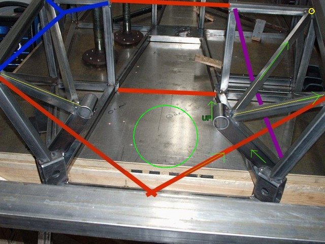
While I agree with Cymtrix's chassis upgrades, in this case I'm not sure they are required. See picture below.
Left engine mount torques upwards. There are tubes from my engine mounts, to the footwell bulkhead (yellow dot). The bulkhead is fully triangulated
so should be solid.
With those tubes, and the red tubes I don't see how the upper engine bay can lozenge. The lower I'm not sure about. The hole where the
oilpan goes (green circle) is not easy to triangulate. Once I shorten my sump I may be able to use aluminum sheet in shear.
The only other open hole is where the purple line is. I may do better trying to fit that as a bolt in.
Just doing what makes sense to me so I could be wrong  . Seems like using engine mount tubes to the bulkhead makes the blue Y obsolete.
Cheers.


Rescued attachment mounts2.jpg
C10CoryM - 30/11/08 at 06:34 PM
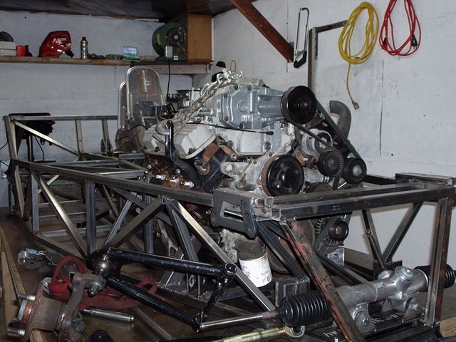
Here is a picture of the lumps in place and a nearly completed (tacked) chassis. It's now welded.
I will try to bring my camera to the shop today for better pics.


Rescued attachment ein.jpg

 . Seems like using engine mount tubes to the bulkhead makes the blue Y obsolete.


