João


Rescued attachment FrtSuspBrackets.jpg

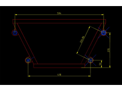
Is it my inhability with Autocad R14 or following the dimensions for positioning the brackets leads to a very odd top one?
João


Rescued attachment FrtSuspBrackets.jpg
If you are comparing to the ones in tho book then when you draw it on CAD all of the dimensions will be different. It all depends on what you take as
your baseline.
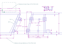
Heres my version of it (sorry if the image is huge!)
The brackets are the GTS tuning ones not the book ones  . And sorry for the stupid accuracy on the dimensions...like to see you make it taht accurate
tho
The Top wishbone brackets have also been moved and the wishbones are designed to keep the 5.3 degree castor angle.
Cheers
[Edited on 16/2/04 by flak monkey]
[Edited on 17/2/04 by flak monkey]


Rescued attachment Front Suspension Mounting Braket Positions.jpg
quote:
Originally posted by flak monkey
If you are comparing to the ones in tho book then when you draw it on CAD all of the dimensions will be different. It all depends on what you take as your baseline.
Cheers
The conversions between mm and inches in the book are not accurate! So you have to stick to one or the other in your build 
Glad to help
ahhh, that explains me scratching my head for several hours at various absurd times of the day trying to work out why I have a 2 mm gap when
everything seemed to be emasured accurately. I would have thought good ol' RC would have done his homework....but then again so should I.
The drawings are very handy by the way, thanks for the posts!.
Cheers
Mark
Wasn't Ron's original design to have a castor of 5'30", which is 5.5 degrees rather than 5.3? Not that I think it makes a huge difference - I've seen both used but I built assuming 5.5.
It definately says 5.3 degrees in my book (Edition 2)  (you had me worried there for a minute) not that .2 degrees will make a huge amount of
difference.
Cheers
Well that's not fair, now I'm worried instead  . Thinking way, way back, I remember now - reading 5.30, I thought: who would use such an
odd number for caster? So I assumed he must have meant 5d30'. Not having access to a book donor to check, I to designed mine to use that. I
don't think I'll worry, even Ron says +/- 0.3d in the book. At least now I know why I see 5.30 everywhere...
quote:
Originally posted by flak monkey
It definately says 5.3 degrees in my book (Edition 2)(you had me worried there for a minute) not that .2 degrees will make a huge amount of difference.
Cheers
Like i say, i doubt +/-0.2 degrees will make much difference, though it will change the positions of the brackets by a few millimetres!
Even Ron says the position can be +/- 0.3 degrees (even though his design gives nowhere near 5.3!!!)
Cheers 
IIRC (it was quite some time ago, 1st edition), it was Ron's strange notation - 5.30, that got me thinking. I mean really, who could build castor
to 2 decimal digits of precision? I was already suspicious from the other book errors, and when I looked up standard castor settings for other cars
they were all given to the nearest 1/2degree (or 30' .
.
Knowing I couldn't achieve the 12 digits of precision in my build that Dave clearly has planned in his (from his drawing) 
 , I went with 5
1/2 degrees.
When I had a look at my book last night I noticed that he says you could add as much as 30 degrees of camber - but it might wear the tires a bit.
LOL, no kidding  . I think he meant to say 3 degrees - surely you couldn't dial in 30 degrees without some very custom a-arms and a completely
different shock arrangement...
In all fairness to Ron and his book errors, I suspect there was more than one hand in the drawings, text and proof reading.
I posted a question about this a short while ago - my theory is that the book gives exactly half the castor it thinks it's giving - I moved my
lower mounts 10mm forward in the light of a number of posts saying the self centring on the steering was an SVA fail, that way I can stick with book
top wishbones.
Cheers
Bob
Hi all,
I have spent the day 3D Cad modelling all the suspension on our Locost GTS kit, as i have been playing with some components to make them lighter and
prettier etc..
I have now got a drawing available (PDF format if you want it electronically) of the bracket locations.
Basically to get 5.30 degrees of castor on a Sierra upright, you need a symmetrical lower wishbone (no offset in the balljoint position), the top
wishbone needs a 19mm rearwards offset from centreline, and its mounting brackets should be be centralised between the lower brackets in the side
view. This is for use with a concentric mushroom adaptor (available from me cheaper than anyone else!! www.gtstuning.co.uk)
Obviously this setup is for use with my suspension brackets and wishbones etc...
Kind regards,
Darren
The most important thing is you have enough castor and exactly the same ammount both sides.
Exact postioning of top pivot depends on wishbone design --- MK offset the ball joint by a few mm towards the rear of the wishbone centre line to
give more castor. It also allows the castor to be quickly altered just by flipping the wishbone over, also make the top brackets slightly wider to
allow for fine adjustment using spacers/packing washers.
Castor and king pin inclination are closely related but as the only way to adjust the king pin inclination is to alter the camber you may find that
using a lot of caster requires a bit more negative camber when the wheels are in the straight ahead position.
quote:
Originally posted by britishtrident
MK offset the ball joint by a few mm towards the rear of the wishbone centre line to give more castor. It also allows the castor to be quickly altered just by flipping the wishbone over

quote:
Originally posted by britishtrident
Castor and king pin inclination are closely related but as the only way to adjust the king pin inclination is to alter the camber you may find that using a lot of caster requires a bit more negative camber when the wheels are in the straight ahead position.
mushroom insert? is that the piece welded to the top of the upright so you can use a normal upper balljoint? If so you can do what you like with it -
the castor angle won't change - the castor angle is angle between perpendicular and a line between the pivots, and these are set by the
wishbones.
OK shoot me down in flames........
Cheers
Bob
PS OK thought about this a bit more - on a real castor (like you get under an office chair) the castor ANGLE is 0 but you get a castor effect because
the steering axis as physically in front of the wheel. Moving the mushroom could give this effect, a bit! Now I have to work out why car manufacturers
don't ever do this....
Bob,
The mushroom is not welded into the knuckle, it is clamped just like the original suspension strut. The tapered hole is machined in offset so if you
rotate the mushroom, you can effectively alter the castor, but this will also alter the KPI and camber at the same time.
quote:
Originally posted by Bob C
PS OK thought about this a bit more - on a real castor (like you get under an office chair) the castor ANGLE is 0 but you get a castor effect because the steering axis as physically in front of the wheel. Moving the mushroom could give this effect, a bit! Now I have to work out why car manufacturers don't ever do this....
