Description

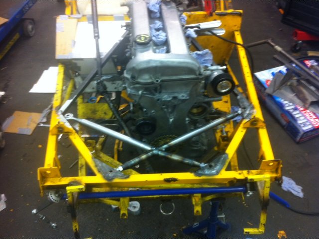
Here's a picture of my cross-bracing spider - it meets the new diagonals nicely.
I've made it with rose joints to aid location, and have used brackets top and bottom to secure each corner to the chassis. I used upper and lower
brackets because:


Can you not make the last corner top plate "bolt on" using a few crush tubes? Put the spider in, bolt on the last top plate, bolt spider to plates, done?
or turn the joint through 90 degrees, and weld the plates in a "Slot in" formation to the gussets?
Dear MakeEverything
I see now that I had kept myself unnecessarily constrained to 2 dimensions. It may still mean cutting out a bracket though, and it's a pity
because the welding is really neat. I find it very easy to be neat with tig on the bench, but it's far harder on the car.
Very bling, but can't help feeling you'd be better off ensuring the suspension mounts are less floppy...
DH2
Hi DH2
I think they're fairly crucial, and if they're shiny so much the better. The fury engine bay lacks lateral strength across the bay and means
the suspension struggles sometimes due to lack of front-end tortional rigidity. I've invested in anti-roll bars, new shocks and springs and I
want to give them the best chance to operate. Looking at it from the top down, the forces now go where they should and don't end up in the middle
of a member.
Saying that, reinforcing the front dangly corner where the rocker arm goes is on the list. It's a classic fury weak point. I've noticed the
latest chassis are gusset there, but my anti-roll bar goes through that. I have some gusseting in underneath (not visible in the shot) but am looking
to tie more in.
Finally, the bottom wishbone and top rocker brackets are coming off, to be replaced with height adjustable brackets on the top, and the bottom
wishbone is being replaced for one with captive spherical bearings, rather than the current arrangement (LDV ball joint, 3/4UNF loaded in bending).
This will strengthen the front up to help me retain an accurate geometry.
quote:
Originally posted by MakeEverything
or turn the joint through 90 degrees, and weld the plates in a "Slot in" formation to the gussets?
I'd still struggle unless the opposite (bottom right) bracket was also vertical.
The advantages are easy extraction - the disadvantage is that I'd lose the gusseting I've got for free (the main reason why I went
horizontal in the first place).
The more I think about it, the more I think welding a pair of brackets onto the spider and then running a turn-buckle to the top left corner seems the
right way. The turnbuckle can just then be loosened off, wound in until one of the rose joints pops out, and then the whole arrangement will come free
as it does now. Disadvantage is aesthetic only.
Thanks to everyone who posted advice on this thread - I'm pleased to announce I've sorted the problem, and in most of these situations, the
solution is really simple. It came to me when I was winkling the spider out from the three existing brackets; I had somehow got my head stuck in the
idea that all the brackets had to be the same shape, and when I was extracting the spider I found that it just needed a slightly different shaped
bracket to come out.
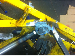
Here it is:


Description
The welds are fine to my eye, and looking at the blue line, I have the temperature about right - it's not burning back too far. Of course I also
get the extra rigidity of the gussets in place. What isn't visible in the picture is a cross-piece in place at the front in the vertical plane to
give me some tortional rigidity.
I'm doing a dry-fit before I put in an extra cross-member infront of the engine which will mean the entire front suspension is now in a proper
rigid box. I also have a (narrow) route to run some 10mm tube from the bottom of the chassis to the very front left hand and right hand corners to
support the rocker arm.
and here is the spider in place, all finished, waiting for the powder coating.


Description