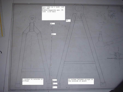
Failing point of my wishbones.
Dale - 20/6/05 at 11:24 AM
2 questions here really.
First is I was wondering if anyone has the knowledge and time to give me the failing point of my arms.
Edit if anyone was looking at this
I am only really intersted in the breaking forces on the part not bump as the loading is on the ball joint plate at the end of the arm so there is
minimal bending force on bump just breaking.
Thanks
end edit
Or sending me in the right direction of doing it myself in the easies way. I have access to turbocad 10 and autocad 14 but its been over 10 years
since I last used it.
Lower arm is on outside edges a symetrical triange with the 2 inside angle equal- so it is 14 inches wide on the base and the 2 sides are 22 inches
long. ( I have just considered the side tubes to be the full length to the ball joint for simplicities sake. The tube is 1 inch by .125 wall.
2nd qutestion is since I have used uprights that were mcphearson strut. The axle spindle is just inline with the nut for the lower balljoint.
Measured I get the alxe inches up from the lower ball joint center and 8 inches below the upper rod end center. This looks to be much more stress on
the lower arm than would be using the book upright which looks to be more or less symetrical which I would assume spreads the load more equal on the
upper and lower wish bones.
Thanks
Dale
[Edited on 20/6/05 by Dale]


Rescued attachment Resize of Resize of front arms1.jpg
want2race - 20/6/05 at 04:26 PM
I am definitely not a fan of the way you angle the end. I can see that corner as a point that will need reinforcement.
I would suggest a top cross piece where the pieces turn inwards. Without it I would imagine that sufficient road holes could cause a camber shift and
or bending of the arms.
Not sure if thats what your asking for or not.. hope it helps
~Jonathan
silex - 20/6/05 at 05:31 PM
Where exactly is the mount point for the shocker going to be ?
Dale - 20/6/05 at 05:36 PM
The shock mount is on the plate that holds the ball joint- so on bump there should be no bending load on the arms.
As far as I can figure out 80% of the load should be on the lower arm as the axle center is 2 inches above the lower ball joint center and 8 inches
below the upper.
I intend to put a plate in the end of the upper arm and taper it back aways which should get rid of that issue- just waiting to make sure my pushrod
for the shockers wil clear before putting it in.
Maybe I should change the question as it may be alot to ask for the numbers. Does anyone know what the bending point calculated is on breaking
for a standard book arm?
Also does turbocad 10 have the capability to calculate stress/ bending point fea or such.
Thanks
Dale
[Edited on 20/6/05 by Dale]
[Edited on 20/6/05 by Dale]


