AdamR
|
| posted on 20/12/04 at 11:58 AM |

|
|
squeezing in a V8 - advice needed!
I'm using a T5 box with my RV8, along with an auto bellhousing and adapter plate to stick them together. I'm going for a +4 chassis, but
having modelled it in SolidWorks, there are obviously going to have to be a few more mods.

The above piccy is how things look sticking to the "sump should be no more than an inch below the bottom chassis rail" rule.
The two things that are worrying me most about this are that the bellhousing badly fouls the Q rail (see other pic below) and the gearbox looks way
too high up. My tranny tunnel would have to be as high as the rest of the chassis. And it looks like the prop would be too high up to meet the
diff.
Then there's the matter of how to fit the plenum and alternator under the bonnet, but I'll worry about that later!

Unfortunately a shortened/dry sump won't achieve much as the bellhousing is just as low. (I was surprised at this, and admittedly I've
not actually mated the bellhousing to the engine yet - they are in different locations a few hundred mile apart - but I'm pretty sure my CAD
model is accurate.)
To get the Q tube to clear the bellhousing I plan two mods: firstly, make the chassis an inch taller. (I know others have done this, but how is it
done without affecting the geometry for the front suspension mounting points?) and secondly, I'm considering cutting out the middle section of
the Q rail and replacing it with another rail laid across the top. Can any of the structural analysis experts tell me how this would affect strength
& rigidity?
As for the position of the gearbox, I'm really not sure. Anyone seen an RV8 and T5 in a seven? They are a popular combination, so I'd be
surprised if it's never been done.
Any comments/suggestions?
Btw, just to give credit where it's due, I used Blueshift's excellent SolidWorks +4 chassis model, which can be found
on this thread. The engine/ T5 box/bellhousing etc are mine
though, and I'm happy to share them if anyone is interested.
|
|
|
|
|
craig1410
|
| posted on 20/12/04 at 01:13 PM |
|
|
Hi,
Check out the pics on my website. I have been through this, albeit using the Rover LT77 gearbox, but this has similar issues. I am currently sorting
out the alternator and SU carb clearance issues (and distributor in fact)
I chose to drop the installation by a further 1" so that my sump is 2" below chassis rails. I will probably make a skid plate out of thick
aluminium (or duralumin or whatever it's called...) to protect the sump and bellhousing and add an extra 1/2" to 1" of ride
height.
In retrospect I wish I had made my chassis 1" taller but it's not essential as I hope I will prove in the coming weeks and months. My
bodywork is from GTS Tuning and I will be adding a bunch of extra pictures to my website soon.
Note that I modified the "Q" tube by cutting out a section and moving it back a bit. I also tilted my "H" tubes either side of
the bellhousing to provide extra clearance while maintaining foot room.
HTH,
Craig.

ps. I'd be very interested in your Solidworks files if the offer is still open. In particular the engine would be great!
[Edited on 20/12/2004 by craig1410]
|
|
|
Bob C
|
| posted on 20/12/04 at 01:17 PM |
|
|
Alternator - alternative mounting is hanging down on the right - then height problem becomes a width problem, I think I've got an old SDI
bracket if you're interested (or I might have used it already - I'll check when I go home) may not be suitable for the poly-V setup
anyway. Re Q rail, if you put a crank in it you should beef up the vertical dimension to 1.5" on the cranked part at least.
Bags of others must have "been there done that" already
cheers
Bob
|
|
|
James
|
| posted on 20/12/04 at 01:24 PM |
|
|
Hi Adam,
How's the welding course? I'm probably coming back in January. Want to pick up my TIG again and hopefully do the C&G for ali and
stainless. Can't be much harder than steel!  
As to your chassis- nice pictures! Could you knock up a Pinto model so I can redo my chassis properly please?
Firstly, I'd highly recommend the chassis height increase- I wish I'd done this myself so help get the soddin Pinto in. MK do it too and
it looks fine. If you want to keep things slightly more elegent then don't continue the height all the way back- drop down an inch at the
'M'(?) tubes (wheel arches).
As for the suspension geometry- well don't worry about the FU1/2 tubes as these have only one bracket on so the angle they lie at isn't an
issue. When it comes to the LA/B/C thing then I would have thought just continuing the length of the verticals(ish) would be fine. Trigonometry (or
solidworks! ) will tell you how much more than an inch it needs to be. You could even cut the ends of the top tube of the 'L' assembly
square as opposed to the 50° angle. I think then that it would be no wider than on a 'short' chassis.
Don't think that is a very good way of explaining what I meant but hopefully yopu can decode it!
Cheers,
James
[Edited on 20/12/04 by James]
|
|
|
Liam
|
| posted on 20/12/04 at 02:25 PM |
|
|
Hello...
Nice Solidworksing by the way!
Well, firstly I reckon you can definately get away with 2 inches of sump sticking down, as others have mentioned.
I've raised my chassis an inch too. Good idea and the proportions still look fine. Much better IMHO than just rasing the bonnet.
Finally you could consider what I've done to my Q tube to get my engine as far back as possible. Probably better structurally than moving it
back or up.
Liam
Rescued attachment DSCF0002.JPG
|
|
|
Racer46
|
| posted on 20/12/04 at 02:38 PM |
|
|
Hi folks. I've been lurking for a while but this is my first post.
If you haven't started cutting steel yet, have you looked at Jim McSorley's other chassis?
It's a +442. 4"wider, 4"longer and 2"taller.
The only problem I see is that it narrows drasticly at the nose.
You should be able to correct this woth little effort.
Happy Holidays,
Pete
|
|
|
Mark Allanson
|
| posted on 20/12/04 at 06:10 PM |
|
|
I have a Pinto in a book chassis and even with a 4 pot, the clearances are VERY small. Make as much room as you can, cos I will guarantee you will use
it.
I would (if starting again) make all the bottom rails from 1"x2" 3mm rhs. A small increase in weight, but a massive increase in strength.
The rhs on end, and compensating for the height but cutting the H tubes an inch shorter.
If you can keep you head, whilst all others around you are losing theirs, you are not fully aware of the situation
|
|
|
craig1410
|
| posted on 20/12/04 at 07:28 PM |
|
|
Hi,
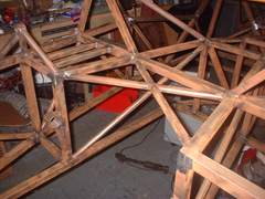
That's a nice design Liam, here is my own solution:

Note the extra triangulation on the side linking with the two short "R" tubes. Also note the standard SD1 engine mounts locate into the
"cradle" in the middle.
Cheers,
Craig.
|
|
|
AdamR
|
| posted on 20/12/04 at 07:51 PM |
|
|
Thanks for all the reponse guys.
quote:
Originally posted by craig1410
I am currently sorting out the alternator and SU carb clearance issues (and distributor in fact)
If you're having problems with SUs, I hate to think the problems the injection plenun will cause.
quote:
Originally posted by craig1410
I chose to drop the installation by a further 1" so that my sump is 2" below chassis rails.... and add an extra 1/2" to 1" of
ride height.
This definitely appeals as it will help solve the bonnet clearance problem at the same time. But what are the compromises to handling etc?
quote:
Originally posted by craig1410
ps. I'd be very interested in your Solidworks files if the offer is still open. In particular the engine would be great!
Yep, I'll post a link later, once I've found somewhere to put them on the web.
quote:
Originally posted by Bob C
Alternator - alternative mounting is hanging down on the right - then height problem becomes a width problem, I think I've got an old SDI
bracket if you're interested (or I might have used it already - I'll check when I go home) may not be suitable for the poly-V setup
anyway.
My alternator is so high because its a Range Rover engine - I was hoping I can swap the mounting bracket for one from an SD1, so if you have one you
dont need that would be great.
quote:
Originally posted by Liam
Finally you could consider what I've done to my Q tube to get my engine as far back as possible. Probably better structurally than moving it
back or up.
Like the idea of that - certainly looks good n' strong.
quote:
Originally posted by James
How's the welding course?
All done now... just need to go and pick up my City & Guilds certificate. May go back in the new year also, as I fancy a crack at TIG.
quote:
Originally posted by James
As to your chassis- nice pictures! Could you knock up a Pinto model so I can redo my chassis properly please?
Not on your life. I reckon I'll have chassis constructed quicker than it took to measure everything and learn SolidWorks. A more sensible
option would be for you to change engines to a V8. You know it makes sense!
quote:
Originally posted by James
As for the suspension geometry- well don't worry about the FU1/2 tubes as these have only one bracket on so the angle they lie at isn't an
issue.
But wont the brackets on the FU tubes be out of position as a result of the change of angle? They have to line up perfectly with the brackets on LA/LB
dont they?
quote:
Originally posted by Racer46
If you haven't started cutting steel yet, have you looked at Jim McSorley's other chassis?
It's a +442. 4"wider, 4"longer and 2"taller.
The only problem I see is that it narrows drasticly at the nose.
You should be able to correct this woth little effort.
Would like a little more length (cough cough) but I dont like the look of the narrow nose.
[Edited on 20/12/04 by AdamR]
|
|
|
AdamR
|
| posted on 20/12/04 at 08:06 PM |
|
|
For those who were after my V8 and T5 SolidWorks models, I've zipped 'em and they can be found at the link below:
http://7v8.net/picture_library/cad/v8_and_t5_model.zip
|
|
|
dblissett
|
| posted on 20/12/04 at 08:21 PM |
|
|
442
has the mcsorley 442 changed because i am building one and i had to widden a standard nose to 26" to get it to fit right
ps the other bonus with a 442 is standard width seats can be used .
cheers dave
|
|
|
craig1410
|
| posted on 20/12/04 at 09:01 PM |
|
|
Adam,
I have a Rover SD1 alternator mount going spare but I'm not sure you will want it. I have it going spare because if I fit it then I would have
to remove the tube which goes across the front corner of the upper chassis rails at the front. It's either tube "S" or
"T" IIRC.
I solved this by buying a Rover P6 alternator bracket. This bolts on to the same fixings as the SD1 bracket but holds the alternator upright rather
than dangling below. This puts it very close to the bonnet but should be okay with a bit of fettling. I bought it for just £10.50 on ebay.
I also toyed with the idea of mounting the alternator down where the power steering pump came from but there wasn't enough room. In my opinion
the P6 mounting arrangement is the best option, especially if you have a taller chassis.
Cheers,
Craig.
ps. Thanks for the Solidworks files!
|
|
|
Bob C
|
| posted on 20/12/04 at 11:19 PM |
|
|
Hi Adam,
I'm afraid I can't seem to lay my hands on the alternator bracket - I must have "tidied it up", looks like the only one
I've got is on an engine...
Apologies
Bob C
|
|
|
Bob C
|
| posted on 20/12/04 at 11:22 PM |
|
|
I'll check in my shed in the light tomorrow, but I'm not very hopeful
Bob
|
|
|
Simon
|
| posted on 20/12/04 at 11:43 PM |
|
|
Adam,
Stop f********g around with things like solidworks and just get on with it.
There are a few of us on here fitting V8's who have already discovered most of the pitfalls
See pic on how to sort clearance issues
ATB
Simon
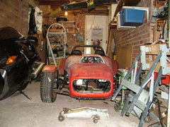 
Rescued attachment 2004_1019Image0032.JPG
|
|
|
phelpsa
|
| posted on 20/12/04 at 11:46 PM |
|
|
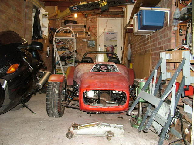
Is that a hayabusa next to the car?
Adam
|
|
|
Simon
|
| posted on 21/12/04 at 12:50 AM |
|
|
Adam
Yip
ATB
Simon
|
|
|
phelpsa
|
| posted on 21/12/04 at 01:05 AM |
|
|
If I had one of those, the engine probably wouldn't be in it.
Adam
|
|
|
Racer46
|
| posted on 21/12/04 at 01:52 PM |
|
|
dblissett,
What I was refering to was that On a 442 chassis tubes F1 & F2 are only 6.1 inches apart where they join LD. On a "book" chassis
they are 8.6 inches apart. On a +4 chassis they are 12.6 inches apart. Yes on the 442 chassis assembly LA,B,C,D is 25.5 inches wide and would
require a 26 inch nose.
|
|
|
James
|
| posted on 21/12/04 at 03:22 PM |
|
|
Adam,
quote:
--------------------------------------------------
Originally posted by James
As for the suspension geometry- well don't worry about the FU1/2 tubes as these have only one bracket on so the angle they lie at isn't an
issue.
-------------------------------------------------
But wont the brackets on the FU tubes be out of position as a result of the change of angle? They have to line up perfectly with the brackets on LA/LB
dont they?
Yes and no!
As long as the top wishbone bolt hole is inline with it's partner on LA/LB then it doesn't matter where the tube is. You can give it quite a
lot of movement aslong as those holes are inline.
Personally, I moved the bottom of my Fu1/2 inwards somewhat so there wasn't that clash between FU1/2 and the lower rear wishbone bolt.
Make yourself a jig like the one in my photo archive and you'll have no problems with the brackets.
Hope that helps,
James
P.S. Sodit, my archive is too messy- here's the photos:
Image deleted by owner
Image deleted by owner
[Edited on 21/12/04 by James]
|
|
|
James
|
| posted on 21/12/04 at 03:25 PM |
|
|
quote:
Originally posted by James
Adam,
quote:
--------------------------------------------------
Originally posted by James
As for the suspension geometry- well don't worry about the FU1/2 tubes as these have only one bracket on so the angle they lie at isn't an
issue.
-------------------------------------------------
But wont the brackets on the FU tubes be out of position as a result of the change of angle? They have to line up perfectly with the brackets on LA/LB
dont they?
Yes and no!
As long as the top wishbone bolt hole is inline with it's partner on LA/LB then it doesn't matter where the tube is. You can give it quite a
lot of movement aslong as those holes are inline.
Personally, I moved the bottom of my Fu1/2 inwards somewhat so there wasn't that clash between FU1/2 and the lower rear wishbone bolt.
Make yourself a jig like the one in my photo archive and you'll have no problems with the brackets. Just set one of the brackets as your datum
point and take it from there.
Hope that helps,
James
P.S. Sodit, my archive is too messy- here's the photos:
Image deleted by owner
Image deleted by owner
[Edited on 21/12/04 by James]
|
|
|
ned
|
| posted on 21/12/04 at 03:26 PM |
|
|
James,
What you describe means that although the pickup points may be relevant to one another you may have altered the track slightly or require different
length wishbones to get the book geometry/track. You may also in moving the pickup points start to change the roll centres of the front suspension.
Ned.
beware, I've got yellow skin
|
|
|
James
|
| posted on 21/12/04 at 03:29 PM |
|
|
Don't think so mate.
Maybe I haven't explained it very well.
All I'm saying is you can change the vertical angle of FU1/2 (when looking down the length of the chassis). As long as the wishbone bolt hole is
in the same place- it doesn't matter.
Hope that's clearer.
James
|
|
|
ned
|
| posted on 21/12/04 at 03:42 PM |
|
|
Here's a fiagram of what I mean then..
You change the roll centres regardless when you widen a locost chassis as the centre crossover points of the lines traced back from the wishbones when
drawing out the roll centres will have moved. Assuming you are keeping the wishbone locations (top and bottom respectively) in proportion to the book
locations in the taller chassis ie as per your jig, then you are in effect moving the lower wishbone in (as the steeper angle of the vertical tube in
the front bulkhead dictates this) unless yo uare going to alter then length of the top wishbone slightly via the camber adjustment in the ball joints
thread. You are also reducing slightly the front track from the moving in of the bottom pickup point.
hope that all makes sense. I'm not saying it will make the handling and better or worse, but it will affect the geometry slightly. that said,
probably not enough that you'd notice, just making my point.
[Edited on 21/12/04 by ned]
beware, I've got yellow skin
|
|
|
ned
|
| posted on 21/12/04 at 03:43 PM |
|
|
oops, forgot the attachment:
ps the heightening of the chassis is exagerated I know, but shows the subtle change in the cars geometry..
[Edited on 21/12/04 by ned]
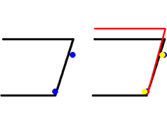 
Rescued attachment inch_taller_chassis.gif
beware, I've got yellow skin
|
|
|