Clay
|
| posted on 20/5/05 at 05:03 AM |

|
|
Review this Chassis Design?
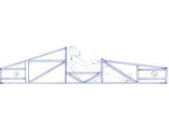
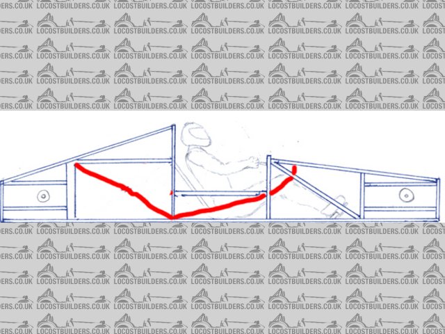
This is a chassis ive been working out on paper, i have more refined drawings, but this is the one i keep altering so its kind of messy. Its similar
to a gt40 configuration, v8 with an audi 5000 tranny in the back, double wishbone independant suspension in the front and the back. Its a 2 seater.
This chassis will be made to the length/width/height measurements to fit underneath an existing body.
The main thing im wondering about is structural rigidity vs. weight.
I have used several X-Braces but lots of chassis designs i see use a single diagonal brace inside squares. Am I just adding dead weight by using
X's instead of a single diagonal braces? or is this additional bracing actually adding structural rigidity?
I want to make the most rigid chassis possible with the least weight added.
The chassis has a squared/triangulated center backbone to add rigidity and provide a place to pass the radiator lines through, this used several X
braces, im really trying to eliminate twisting in the chassis.
I understand this drawing is very crude, but offer any insight you've got.
thanks
*edit*
In newer drawings ive moved the steering wheel position so that the drivers arm is slightly bent, but that detail isnt critical in this drawing, the
chassis rigidity/design is what im interested in.


[Edited on 20/5/05 by Clay]
Clay Marsh
|
|
|
|
|
silex
|
| posted on 20/5/05 at 05:05 AM |
|
|
It says bandwidth exeeded - there is no pic ?
Murphy's 2 laws
1. If it can go wrong it will
2. In case of emergency - refer to rule 1.
|
|
|
Clay
|
| posted on 20/5/05 at 05:12 AM |
|
|
I think I fixed it.
[Edited on 20/5/05 by Clay]
Clay Marsh
|
|
|
silex
|
| posted on 20/5/05 at 05:24 AM |
|
|
thats better - can see it now
Murphy's 2 laws
1. If it can go wrong it will
2. In case of emergency - refer to rule 1.
|
|
|
Fred W B
|
| posted on 20/5/05 at 05:53 AM |
|
|
HI
Your concept is similar to my CANAMSA project, search under that name on here for some discussuion and see my archive
Also go back in the Midengined section posts for a lot of info from various other builders.
One thought, I think you will be short of driver and passenger feet/pedal/steering rack space.
Cheers
Fred WB
[Edited on 20/5/05 by Fred W B]
[Edited on 20/5/05 by Fred W B]
[Edited on 20/5/05 by Fred W B]
|
|
|
silex
|
| posted on 20/5/05 at 06:56 AM |
|
|
On the side view you have two definate week points.
The centre section is lower in height than front and rear and the top rail of the centre section looks to come half way op the vertical rails, whether
the attach to the outer verticals or a horizontal brace between the two sides you show no other support. This means that with your weight in the
middle and going over bumps, the top centre rail will bend those verticals they attach too. You would be better taking the triangulation for the front
and rear section from that point if you know what I mean. Having this week joint between the centre section and the fron and rear may make the chassis
feel bouncy even if it never failed structurally.
A resonable start though - do you have a front / rear view, you cannot always get all the info you need without at least a third view.
Murphy's 2 laws
1. If it can go wrong it will
2. In case of emergency - refer to rule 1.
|
|
|
JonBowden
|
| posted on 20/5/05 at 10:23 AM |
|
|
with reference to silex's comments about the centre section, think about what would break in the event of a bar frontal crash - my guess would
be one of the veritcals attached to the centre section.
This would be uncomfortable since it might leave little room for the driver
Jon
|
|
|
wheelsinsteadofhooves
|
| posted on 20/5/05 at 11:59 AM |
|
|
hi,
looks pretty good. a few comments if i amy though.
as you mentioned you have several x braces. these are a waste of material and hence weigt as the brace is to stop the square "lozenging".
as steel is fairly strong (strong enough) in both tension and compression a single brace will prevent lozenging in both directions, so is
sufficient.
as for the connections, my main concern would be where the rear section joins the middle point. the diagonal braces meet the transverse members but
there is no support from there on. any spaceframe should is essenstially i giant bracket from which eveything, including the driver is mounted - the
words of colin chapman. hence think about where the forces are generated - at the suspension mounts, engine mounts etc, and where they need to go -
the seats, engine mounts etc - the forces need to move the items and so the larger items need more force. now join these points as efficiently as
posssible with straight lines, make consessions so you can actaully sit in the thing, and then use simple bracing fo fill the gaps.
there are a few other issues i would raise like the width of the chassis coming all the way out to the edge of the wheels, and the scale of the wheels
on the side view, but overall not a bad attemt at all.
next stage would be to get hold of some cheap and easily workable material, like balsa wood or narrow drain pipe, and a roll of tape, and make a
mock-up. then you can sit in it and see it in terms if size and positioning of members. it will surprise you.
keep up the great work,
all the best,
zane
|
|
|
Fred W B
|
| posted on 20/5/05 at 12:11 PM |
|
|
"any spaceframe should is essenstially i giant bracket from which eveything, including the driver is mounted - the words of colin
chapm"
I thought that was Staniforth - or was he quoting chapman?
Cheers
FredWB
|
|
|
Clay
|
| posted on 20/5/05 at 02:15 PM |
|
|
i believe it was staniforth but anyways...
The reason the mid section is lowered is because the driver has to enter the chassis through that point. I've been stressing over that weekness
also but i dont see any other way around it. If the car is going to have opening doors on each side, the driver will have to have a place to get in
and sit down. How can I provide room for the driver to enter the car, And strengthen that weak point? the only thing I can think of is a hinged upper
brace, even in height with the upper member of the front and rear upper members, that could swing out with the door, but lock solid when the door is
closed, thoughts?
I have trouble drawing circles lol the wheels were drawn several times and i couldnt get their size proportionally accurate, sorry about that, ill get
a circle stensil for my next drawing.
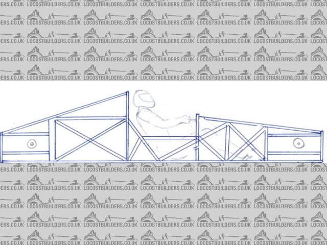
Thank you for the comment about adding useless weight with the X-braces, I have redrawn the chassis with out these X-braces and will post it in this
thread.
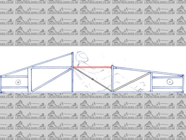
In this next drawing I have eliminated the X-Braces, and left the wheels off since they are not important in this drawing.
The diagonal brace behind the drivers back is just slightly inside of the outter rails of the chassis and secures the rear vertical to the
chassis' floor.
In an ideal situation i would run a bar from the tops of the two verticals, and from the top of the engine area straight forward to the top of the
steering wheel area. But like I said before, how will the driver get in the car?
The last idea I would like to propose is this... Lets say I took the center section thats lowered, and essentially extended that box of support
forward and backwards on the chassis, so basically the bottom of the chassis would be a triangulated box of that height, then any part of the chassis
taller than that would be tacked ontop of that box. would that eliminate some of the weakness?
Here is the new picture...
 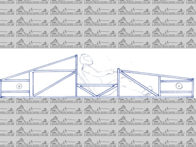
Rescued attachment Chassis3.jpg
Clay Marsh
|
|
|
Clay
|
| posted on 20/5/05 at 02:25 PM |
|
|
quote:
Originally posted by wheelsinsteadofhooves
as for the connections, my main concern would be where the rear section joins the middle point. the diagonal braces meet the transverse members but
there is no support from there on.
there are a few other issues i would raise like the width of the chassis coming all the way out to the edge of the wheels
zane
Zane, in the top view, i made the chassis go out to the edge of the wheels because the body of the car is going to sit on top of the bottom frame. Is
there a reason why I should not do this? Should the chassis width be shortened?
Also, where could I add more support for the rear vertical? I assume the first thing you mentioned was in the top view. The diagonals going from the
center to the rear section do only go to the transverse member somewhere between the transmission and the engine block, but if you look at the side
view, the top members for the rear go from the highest point in the middle of the chassis, all the way to the furthest rear point on the chassis. I
could make the diagonals viewed in the top view extend all the way to the furthest rear point of the chassis also, but then where they attach to the
center section couldnt be attached at the widest point, or the members would interfere with the wheels and such. Would you reccomend making the rear
diagonals viewed in the top view drawing more narrow in relation to eachother so they could be extended all the way to the rear? I thought it was
fairly important that the diagonals viewed in the top view drawing attach to the center at their outer most points.
Clay Marsh
|
|
|
flak monkey
|
| posted on 20/5/05 at 02:30 PM |
|
|
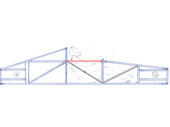
On your last drawing the design is ok, but as you have cut-away cockpit side you have some good bending loads on the cockpit tubes.
A simple and easy to apply rule when it comes to spaceframes is all loads should pass through nodes (there 3 or more) tubes meet.
Hence I would add in some tubes as i have drawn. Follow the angle of the cockpit braces up to meet the others, then bring a tube straight down (or up)
to meet at the node. That modification should bring stiffness up considerably.
Cheers,
David
Rescued attachment chassis.jpg
Sera
http://www.motosera.com
|
|
|
flak monkey
|
| posted on 20/5/05 at 02:32 PM |
|
|
Or you could do away with the V-bracing on the cockpit sides and do something like this, depending on the layout of all your tubes really! Its very
difficult to say what would benefit you with only 2d drawings.
(Sorry about my crappy examples!)
[Edited on 20/5/05 by flak monkey]
Rescued attachment chassis.jpg
Sera
http://www.motosera.com
|
|
|
ned
|
| posted on 20/5/05 at 02:57 PM |
|
|
here are my takes on it, narrowing but maintaining the low section for entry to the car. normally on an open top car you step over the side onto teh
seat, then sit yourself down into the footwell.
and the x-bracing can be removed if preferred 
chassis design
chassis design2
looking at it again, if you wanted you could extend the horizontal member in the middel of hte chassis at either/both ends til they meet with the
x-braces..
[Edited on 20/5/05 by ned]
beware, I've got yellow skin
|
|
|
Clay
|
| posted on 20/5/05 at 04:23 PM |
|
|
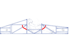
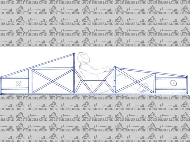
now?
Here is a new idea I tried, the red bar is hinged at the front and swings out with the door, but locks solid when the driver is seated and the door is
closed. Is this a bad idea?
I figure the X-brace in the middle might allow just enough space for the driver to get into and out of the cockpit. It will be akward but similar to a
race car with a serious roll cage i think. This car is designed with a removable hard top, but im trying to design it for getting in and out of the
car if the roof is on.
thoughts on this new revision?
Clay Marsh
|
|
|
JonBowden
|
| posted on 20/5/05 at 04:25 PM |
|
|
Ned, this looks like a big improvement.
Clay, You might find it usefull to make a model of your design. Have a look at this thread :
http://www.locostbuilders.co.uk/viewthread.php?tid=21936
Once you have made a model, you can try twisting it to see where the weak points are.
Personaly I would also test a model to destruction to see what hapens inaan accident.
Best wished for building your design
Jon
|
|
|
flak monkey
|
| posted on 20/5/05 at 04:31 PM |
|
|
I have to say I think that neds second one is the best.... 
Sera
http://www.motosera.com
|
|
|
Clay
|
| posted on 20/5/05 at 04:49 PM |
|
|
quote:
Originally posted by flak monkey
I have to say I think that neds second one is the best....
Will you back that up with some reasons?
Ive been looking at neds 1st chassis as the best one so far because it allows for the driver to lift his leg out and over the side bar to get out.
Clay Marsh
|
|
|
flak monkey
|
| posted on 20/5/05 at 04:54 PM |
|
|
I was looking at it as the best technically (probably with some playing about in 3d you could lose some of the cross bracing). If entry and exit
(quickly) are important then you have to make compromises.
The second one is fully triangluated with minimal bending loads on any of the tubes. The top one is missing the triangulation to the top of the
'scuttle'. Though how much difference this makes to the stiffness is anyones guess...
The first one is indeed easier to get in and out of than the second. And if that is important then thats the one to go for.
Also, the one in your drawing doesnt need the cross brace if you change the direction of either the front or rear brace.
David
[Edited on 20/5/05 by flak monkey]
Sera
http://www.motosera.com
|
|
|
Clay
|
| posted on 20/5/05 at 04:55 PM |
|
|
Now that I think about it, I think using T-Tops that are hinged in the middle so they open straight up like butterfly wings would allow the passenger
or driver to just lift the top, step in, and close the top over him once hes in. That would get rid of the pesky weak center problem.
And they could just be removed to make the car a convertible.
Lets say we've eliminated the problem about needing clearance for the driver to get in and out of the car, would it be best to just have a setup
like the last one i posted, with the x brace in the middle, and the red bar a solid mounted member?
[Edited on 20/5/05 by Clay]
Clay Marsh
|
|
|
flak monkey
|
| posted on 20/5/05 at 05:00 PM |
|
|
If you wish to have a higher top rail then you could do this. Theres no reason for any cross bracing.
Rescued attachment chasis1.jpg
Sera
http://www.motosera.com
|
|
|
Clay
|
| posted on 20/5/05 at 05:19 PM |
|
|
thanks, that makes sense for if the upper brace can be that high.
Clay Marsh
|
|
|
Clay
|
| posted on 20/5/05 at 06:13 PM |
|
|
quote:
Originally posted by flak monkey
The top one is missing the triangulation to the top of the 'scuttle'. Though how much difference this makes to the stiffness is anyones
guess...
If the scuttle is the part where the gauges would be directly in front of the driver (sorry im not familiar with this word), this portion of the
chassis is composed of zero force members i believe. So they dont need to be heavily reinforced....to my understanding.
[Edited on 20/5/05 by Clay]
|
|
|
flak monkey
|
| posted on 20/5/05 at 07:03 PM |
|
|
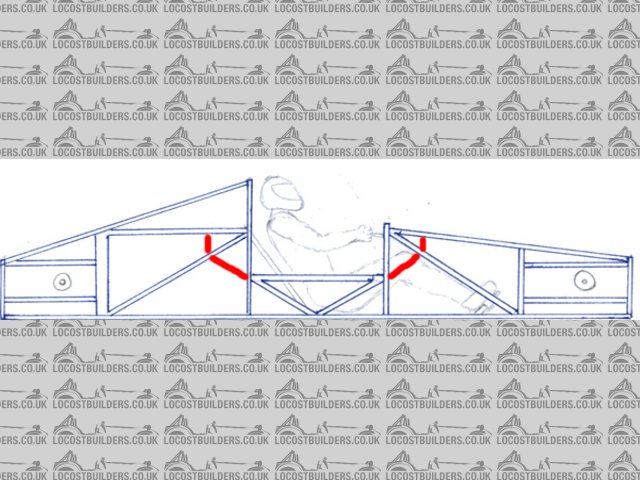
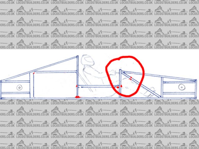
Think of all chassis members as lines of force. In your original low sided design the area circled is subject to bending forces toward the driver.
These forces would come from the suspension or from cornering etc. By continuing the top rail higher up as in the latest one you have controlled these
forces. Likewise neds design with the double triangulation would work in the same way.
Remember the ideal for a spaceframe is to have all members in compression or tension. But this is not alway practical (in the case of easy entry/exit
for you).
The best way to design a spaceframe is come up wth something close on paper. Get it drawn in CAD and analyse it using FEA. Once that model is good,
then build a prototype and test it on a torsion test rig. Of course ot everyone has access to these things. At the end of the day, any of the designs
you have presented would work, it just comes down to how efficient you want the design to be, and what compromises you are willing to make.
David
PS my 3rd yr uni project is on chassis design next yr
[Edited on 20/5/05 by flak monkey]
Rescued attachment chassis.jpg
Sera
http://www.motosera.com
|
|
|
Clay
|
| posted on 20/5/05 at 07:11 PM |
|
|
I understand what you are saying, but in Ned's first design, the node you selected at the scuttle isnt encountering any forces, in that design,
the node that would be moving towards you, that needs support is the one infront of the scuttle, just in front of the drivers knee.
In the first design, you could completely remove the 2 scuttle members and the chassis rigidity would not change at all. so they dont need support
because its taken care of by the member on front of it. right?
See what im saying?
Clay Marsh
|
|
|