jonbeedle
|
| posted on 23/5/05 at 06:36 PM |

|
|
Diagonal chassis tube in engine bay
Need to remove and reposition diagonal chassis tube in engine bay to make room for my Stryka exhaust system. Any reason why I
shouldn't?
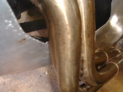 
Rescued attachment Dscf0005.jpg
"Everyone is entitled to an opinion however stupid!"
|
|
|
|
|
jonbeedle
|
| posted on 23/5/05 at 06:37 PM |
|
|
.......and a pic taken from inside.......
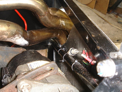 
Rescued attachment Dscf0008.jpg
"Everyone is entitled to an opinion however stupid!"
|
|
|
Avoneer
|
| posted on 23/5/05 at 07:04 PM |
|
|
No reason at all not to move it.
Put two shorter ones in from the top two corners daigonally down to the middle of the bottom rail - that's how it's done on both sides on
the Avon...
 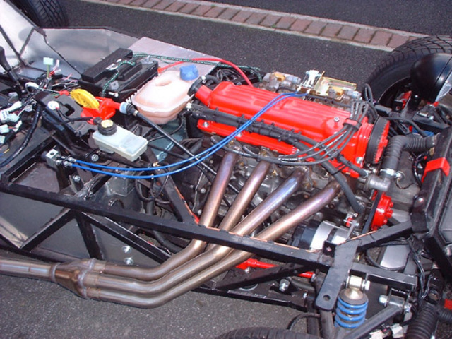
Rescued attachment completeengine.JPG
No trees were killed in the sending of this message.
However a large number of electrons were terribly inconvenienced.
|
|
|
cymtriks
|
| posted on 23/5/05 at 07:53 PM |
|
|
Analysis of tube R mods
tube R
The following are results of my analysis of engine bay mods (tube R variations)
Here are the results for chassis stiffness in ftlbs.
The book chassis:- 1155
My modified chassis design as described in earlier posts:- 2505
Both the above have standard tube R layout.
The book chassis with two shorter R tubes, one on each side of the engine, to allow wide engines to be fitted. This is a fairly common mod:- 907
My mods but with two short R tubes as above:- 1898
The conclusion is that fitting two short R tubes instead of one long one as in the book reduces the stiffness by about 25%
The book chassis but with two Y braces, one on each side of the engine, from where the H tubes meet tube Q to the tops of FU1/2:- 1215
My high stiffness design but with two Y braces as above has over 2700. A picture of this is in the photos section.
So the best way to get more space in the engine bay is to use a double Y brace. This being 33% stiffer than using two short R tubes.
|
|
|
Avoneer
|
| posted on 23/5/05 at 10:33 PM |
|
|
Sorry, do you mean the one horizontal that you seem to have removed, or the vertical round bar one?
Pat...
No trees were killed in the sending of this message.
However a large number of electrons were terribly inconvenienced.
|
|
|
jonbeedle
|
| posted on 24/5/05 at 05:53 AM |
|
|
Pat,
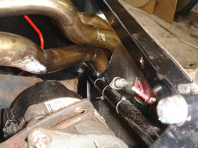
No you were right. It's the round tube which is under the bottom exhaust pipe. (See last pic above) I think Cymtriks thinks I meant the top
rail.
And I haven't removed anything yet! I reckon I'll do it like the Avon as you suggest.
Cheers
Jon
[Edited on 24/5/05 by jonbeedle]
[Edited on 24/5/05 by jonbeedle]
"Everyone is entitled to an opinion however stupid!"
|
|
|
MikeRJ
|
| posted on 24/5/05 at 01:45 PM |
|
|
quote:
Originally posted by jonbeedle
Pat,
No you were right. It's the round tube which is under the bottom exhaust pipe. (See last pic above) I think Cymtriks thinks I meant the top
rail.
No, I think Cymtriks was talking about the same tube. If you removed the top rail the chassis would have the rigidity of a wet paper bag.
The advantage of the two short tubes is that is gives more support to the engine mountings, which otherwise put quite a high bending load on the lower
rails.
I also suspect (but have no proof) that an upright member between the lower and upper chassis rails where the two shorter R tubes would meet would
also restore most of the lost rigidity, but of course would be impossible to fit in your case.
|
|
|
jonbeedle
|
| posted on 24/5/05 at 02:02 PM |
|
|
If I do it like the Avon though , which will be possible, It would end up more rigid than the original design don't you think? Because the tubes
will be a bit stronger being 1" RHS as opposed to 0.5" tube or whatever it is.......
"Everyone is entitled to an opinion however stupid!"
|
|
|
britishtrident
|
| posted on 24/5/05 at 03:36 PM |
|
|
What about offsetting the engine to the left by 30mm and raising it by 15mm.
|
|
|
Avoneer
|
| posted on 24/5/05 at 03:47 PM |
|
|
Tube R is the top one, not the side ones we are talking about.
Use two pieces of 3/4" round on each side and it will be fine.
Pat...
No trees were killed in the sending of this message.
However a large number of electrons were terribly inconvenienced.
|
|
|
jonbeedle
|
| posted on 24/5/05 at 06:11 PM |
|
|
If I offset the engine any more than it already is, the alternator will be through the side of the car. Any higher and the vacuum thingy will foul on
the top diagonal rail!
Cheers
Jon
quote:
Originally posted by britishtrident
What about offsetting the engine to the left by 30mm and raising it by 15mm.
"Everyone is entitled to an opinion however stupid!"
|
|
|
jonbeedle
|
| posted on 24/5/05 at 06:12 PM |
|
|
I might go down this route but I'm exploring the possibilities of modifying my exhaust. See here
http://www.locostbuilders.co.uk/viewthread.php?tid=26623
Cheers Jon
quote:
Originally posted by Avoneer
Tube R is the top one, not the side ones we are talking about.
Use two pieces of 3/4" round on each side and it will be fine.
Pat...
[Edited on 24/5/05 by jonbeedle]
[Edited on 24/5/05 by jonbeedle]
"Everyone is entitled to an opinion however stupid!"
|
|
|
NS Dev
|
| posted on 25/5/05 at 11:21 AM |
|
|
A short answer, as I can't answer the initial question, but "the way it is on the Avon" looks very poor in terms of load paths to me
but never mind, it'll still work!
|
|
|
craig1410
|
| posted on 25/5/05 at 12:17 PM |
|
|
The long round tubes on the book (TR1 and TR2 IIRC) chassis are too long anyway and there is considerable advantage to be had by splitting this into
two or even three "zig-zags"
It has also been said before that 1" round would be more sutable instead of 3/4" or do as I have done and use 1" square.
I'll post a pic of my setup in a moment if I can find one.
[Here's one]

Cheers,
Craig.
[Edited on 25/5/2005 by craig1410]
|
|
|


%20(WinCE).JPG)