robertst
|
| posted on 19/5/06 at 09:10 PM |

|
|
need help from the engineers (or able people) please
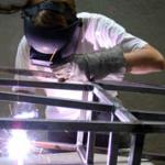
my build has officially started, and the first task is to build my hoist to remove the donor engine. i have drawn some plans and i wanted to ask you
guys if the materials chosen are ok.
basically they are RHS tube : 40x40x3mm and
50x50x3mm
i guess thats enough to lift 150kg or so the pinto weighs.
thanks
Tom
[img]/upload/hoist_side.jpg[/img]
[img]/upload/hoist_top.jpg[/img]
[Edited on 19/5/06 by robertst]
Tom
|
|
|
|
|
robertst
|
| posted on 19/5/06 at 09:11 PM |
|
|
right.. that code doesnt seem to work....
 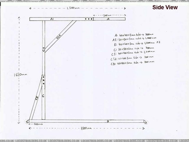
Rescued attachment hoist_side.jpg
Tom
|
|
|
robertst
|
| posted on 19/5/06 at 09:12 PM |
|
|
and the base...
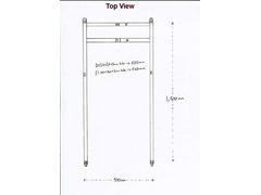 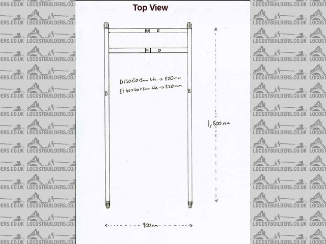
Rescued attachment hoist_top.jpg
Tom
|
|
|
Howlor
|
| posted on 19/5/06 at 09:28 PM |
|
|
Sizes look to be about right although quality of the weld will be more important. If I was you I would also lower the point at which C1a meets C1,
also move C1a further out toward the load on the top beam. This way you will place less bending moment onto C1.
Steve
|
|
|
kb58
|
| posted on 19/5/06 at 09:30 PM |
|
|
I don't know how strong that tubing is in bending, but if it does fail it'll be right at the C1/C1A junction. Whether that happens
depends on the weight of what you're lifting and how far out it is from the upright tubes. I think I'd add some bracing between the
adjustment bolts.
[Edited on 5/19/06 by kb58]
Mid-engine Locost - http://www.midlana.com
And the book - http://www.lulu.com/shop/kurt-bilinski/midlana/paperback/product-21330662.html
Kimini - a tube-frame, carbon shell, Honda Prelude VTEC mid-engine Mini: http://www.kimini.com
And its book -
http://www.lulu.com/shop/kurt-bilinski/kimini-how-to-design-and-build-a-mid-engine-sports-car-from-scratch/paperback/product-4858803.html
|
|
|
coozer
|
| posted on 19/5/06 at 09:31 PM |
|
|
Removing the engine from the donor:
1: Remove all the bolts from the rear axle, front crossmeber and the gearbox mounting, then lift the body off. Yahoo! Yahoo!
2: Hoist the back, remove the prop, then the gearbox, unwind the bolts holding the rear axle , drop it down then wheel it out the back.
Then get a hoist and lift the engine out.
3: Just like 2: but instead of lifting the engine out on a hoist, cut the slam panel and front panel off with a sthill saw and just haul the engine
out the front!!
Took me 7 hours to remove the lot withour kifting anything out,
Cut the front off and then sold the body on for £30!!!!!! 
[Edited on 19/5/06 by coozer]
1972 V8 Jago
1980 Z750
|
|
|
Mansfield
|
| posted on 19/5/06 at 09:33 PM |
|
|
Increasing the length of C1A, but maintaing the 45 angle, increasing D to E and length of CB (therefore angle CB-C-B)would stengthen it up.
To me, the critical welds are:
CB to E
C to D
CB to C
The addition of some C to D bracing would help any potential failures resulting from any 'offside to nearside of the donor' loads.
Neck on the block verdict: It will lift your engine but it will bend a bit, dont think it will fail.
|
|
|
Mansfield
|
| posted on 19/5/06 at 09:38 PM |
|
|
Oh yeah, I forgot, beware of tarmac in hot weather or get some bigger wheels.
This can be quite a disappointing thing to discover at the wrong moment.
|
|
|
JoelP
|
| posted on 19/5/06 at 10:02 PM |
|
|
a completely different approach would be to have a strong beam supported above the car at both ends, with a simple block and tackle to do the lifting.
This would be a far simpler system if you could find a way to hold the beam up properly. Theres only one beam, it can only bend in the middle, theres
less chance of it toppling over of sinking into the ground, theres also no hydraulic system to worry about. Roll the car under it, raise the engine,
and roll it back out.
[Edited on 19/5/06 by JoelP]
|
|
|
robertst
|
| posted on 19/5/06 at 11:02 PM |
|
|
thanks a lot for your replies. i'll do the adjustments to the measurements. i was going to do the beam thing, actually it was my first plan for
the hoist, but it's too big, and not very manouverable.
coozer, i had in mind your point three from the beginning!!! why would i need to lift the engine, when i can drag it out from the front.
i just really need this hoist to support the weight. i'll probably lift the engine a couple of inches.
again thanks!
Tom
|
|
|
tadltd
|
| posted on 19/5/06 at 11:08 PM |
|
|
why not hire a hoist for the day...?
Best Regards,
Steve.
www.turnerautosport.com
|
|
|
robertst
|
| posted on 19/5/06 at 11:11 PM |
|
|
yeah that would be much simpler... but the problem is that there isnt one i can rent. or buy for that matter! i have sourced them in specialized
stores, but they cost around 500 quid and are designed to lift a lorry's engine. not exactly my cup of tea if you know what i mean.
cheers
Tom
|
|
|
scoop
|
| posted on 20/5/06 at 07:24 AM |
|
|
How about two mates (strong ones), a scaffold pole and a piece of rope and you to guide it out. Job done
Steve.
|
|
|
JB
|
| posted on 20/5/06 at 07:24 AM |
|
|
Lifting Frame
If you are unsure of the design of the structure then build a simple wodden model (I use 6mm x 6mm wood available from B&Q and a glue gun) and
load it and see where it bends.
John
PS The wood and glue gun will come in handy for doing models during your build.
|
|
|
tks
|
| posted on 20/5/06 at 07:57 AM |
|
|
mhhh
Well
i would make c1 larger just near the adjust holes!
Also i think you should use the smallest holes possible because obviously they will be the weakest point.
If i was you i just used some M8 8.8 grade bolts.. (in the end there isn´t any load on them!!) its just the bar don´t fells out when there is no
weight
also i wouldnt drill them in the direction you have, but better from top to ground.
It makes the sidewalls stronger
and that are the muscles of your hoist.
Like mentioned before from C to D/B is needed!
Regards,
Tks
The above comments are always meant to be from the above persons perspective.
|
|
|
cossey
|
| posted on 20/5/06 at 08:10 AM |
|
|
that is most likely to fail by the top adjust hole on c1/c.
as you are unlikely to need height adjustment i woul just have 2 holes slightly further apart and put a bolt through both of them. its much stronger
plus you can still disassemble it for storage.
finally a use for stress analysis
|
|
|
robertst
|
| posted on 20/5/06 at 12:21 PM |
|
|
wait wait wait... so three bolts give less strength than two? maybe spacing all three out...i'm using the bolt thing to be able to disassemble
this thing.
i've made C1A longer and maintained the 45º angle, and i also added two bars connecting C to both Bs. i guess that should be able to cope with a
few hundred kgs??
but seriously would it fail completely or just bend?
the pinto with a gearbox must weight around 200kgs?
thanks
[Edited on 20/5/06 by robertst]
Tom
|
|
|
cossey
|
| posted on 20/5/06 at 12:56 PM |
|
|
it wont fail unless you put maybe a tonne or more on it.
i thought the 3 holes were for adjustment so only 1 would have a bolt in it at a time, if all 3 have bolts then it should be fine but i dont think you
need the middle one.
|
|
|
tks
|
| posted on 20/5/06 at 01:04 PM |
|
|
..
make the bolt as small as you can!!!
and do it the other way round!!
"Taladralo en la direcion de B"
The stifness in the bended way will then be maximum and the lateral way will be some less, but you don't need it there! plus you have got the
extra 2 bars.
Sow drill the holes in the B direction!
its the same in the upper tube like i already said.
I also don't see to many problems!
also because its just 800mm or something
sow the arm isn't very long!
but don't fool your self to much, the bending caracteristics go crazy when the unsoported lengt grows..
Think you construction should be fine for 450kgs.
Altough it all depends on the lengt used in theupper bar.
make some pics of your creation and put them together with the desing drawings in you foto archive!!
and offcourse tell us the results!
last bot not least grade 8.8isn't the standard grade sow watch out!!
Regards/Recuerdos
Tks
The above comments are always meant to be from the above persons perspective.
|
|
|
robertst
|
| posted on 20/5/06 at 03:15 PM |
|
|
ok.. i get it.... thanks to all!
gracias tks!
Tom
|
|
|
cossey
|
| posted on 20/5/06 at 04:32 PM |
|
|
sorry about this but ive just actually worked out all the stress etc properly and it will fail.
sigma = (bending moment x distance from neutral axis) / second moment of area
the bending moment is the weight of the load in newtons x the size of the moment arm
200kgx9.81x~1.25m =3066nm
the distance from the neutral axis is alf the width of the tube ie 20mm which is 0.02m
the second moment of area is the width cubed x the depth /12 - the same for the hollow area in the centre =1.01x10^-7
so sigma the stress is ~600mpa, the yield strength of mild steel is 200mpa so the c1 will break at the top of c.
this is without the holes with them it will break much sooner.
the holes should be in the direction in the drawing not in the direction of the legs as you want the material removed to be as close to the centre of
the tube as you look at it from the same view as the first drawing.
|
|
|
robertst
|
| posted on 20/5/06 at 05:21 PM |
|
|
 bot wait... tube C1 goes inside C. and i was probably thinking of making it as long as to touch the base. so theoretically, C1 wouldnt break
because it would act as a lever against C?.... i then thought to leave it just a couple of cms close to the base, hence the 1200mm. bot wait... tube C1 goes inside C. and i was probably thinking of making it as long as to touch the base. so theoretically, C1 wouldnt break
because it would act as a lever against C?.... i then thought to leave it just a couple of cms close to the base, hence the 1200mm.
it might bend then? but i guess 3mm should be enough to widthstand 200 kgs?
i have just realized that by moving C1A closer to the top of C what you say might happen easier.
its just like the wishbones. if the bottom suspension bracket is too close to the chassis, the wishbone will bend.
Tom
|
|
|
robertst
|
| posted on 20/5/06 at 05:32 PM |
|
|
so you would compute the sigma with a length of 870 instead of 1250. then i read that steel has a certain elasticity beyond the yield point where it
will flex but not break until around 400Mpa.
Tom
|
|
|
robertst
|
| posted on 20/5/06 at 05:39 PM |
|
|
yep i get around 338Mpa so the crane would flex which will make me poo in my pants when i do it but it wont break...
it depends on the welds as mansfield said....
[Edited on 20/5/06 by robertst]
Tom
|
|
|
DarrenW
|
| posted on 23/5/06 at 12:27 PM |
|
|
i considered making a hoist - but only very briefly.
I managed to get an extending ali beam from the back of an old ambulance (any beam will do but this has a nice sliding bit for the hoist to fasten.
I placed this on top of garage walls (well only at one side in the end as beam was too short but other end was supported with timber). Block and
tackle hung from beam - engine in with no fuss.
Beam doesnt have to be metal. Lift hoist bought cheap from 2nd hand paper. Nice and cheap and quick.
|
|
|