ChefChristian
|
| posted on 8/3/07 at 06:22 PM |

|
|
how to determine chassic flex, torsion and rigidity
I need some engineering help here guys. This is for my chassis. I am building a simple ladder frame with cross supports and triangulation.
It will be 92 inches long. I understand that bigger diameter is better than larger wall thickness.
I am trying to determine if I can use 50x50x2 or if I need to go up to a 100x50x2+.
Any math that you can run for me would be great. I can find my own answers but I need to know where to look, in what books or what websites.
|
|
|
|
|
Chippy
|
| posted on 8/3/07 at 10:38 PM |
|
|
I may be wrong, but seem to recall. The deeper the chassis rails, 100mm as against 50mm, with X rails of the same dimention will give a chassis that
will flex less. How you cross brase the frame, and attach parts, ie suspention etc. will also have an effect. HTH Ray
To make a car go faster, just add lightness. Colin Chapman - OR - fit a bigger engine. Chippy
|
|
|
JB
|
| posted on 11/3/07 at 12:06 PM |
|
|
Chassis
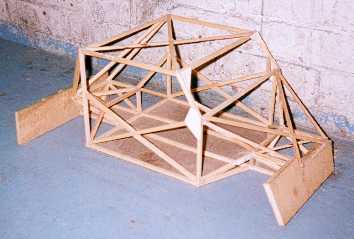
Build yourself a wooden model and play. I used wood from B&Q 6mm x 6mm and a glue gun.
Torsional is important. Build and twist the model, add memebers double them up etc.
You will learn more this way than any maths, books or advise.
Basic rules are:
1) Bigger the section the better.
2) You need everyside of the box triangulated or panalled.
|
|
|
cymtriks
|
| posted on 11/3/07 at 11:22 PM |
|
|
50 x 50 is hopelessly inadequate.
100 x 50 x 2mm wall tube made into a simple ladder with one tube down each side, a front and rear cross member and an X brace with the ends of the X
reasonably close to the suspension pickups will be slightly stiffer and lighter than the book chassis.
The book chasis can easilly be improved by sorting out the triangulation. An improved spaceframe would give the best result for a seven style of car.
|
|
|
MikeRJ
|
| posted on 11/3/07 at 11:34 PM |
|
|
quote:
Originally posted by cymtriks
100 x 50 x 2mm wall tube made into a simple ladder with one tube down each side, a front and rear cross member and an X brace with the ends of the X
reasonably close to the suspension pickups will be slightly stiffer and lighter than the book chassis.
So it will likely be heavier once you add in all the structure required to support the suspension units, the bodywork, upper seat belt mounts etc? A
space frame makes things a lot easier in this respect.
|
|
|
ChefChristian
|
| posted on 12/3/07 at 01:37 AM |
|
|
I have researched the forums under cymtriks, Rorty and Syd Bridge. I am going to be starting to build the frame from wood but want to find a source
for the standard deflection as wood and steel will still be substantially different. This will not be a 7esque frame. very go-cartish with almost no
bodywork or suspension.
|
|
|
Doug68
|
| posted on 13/3/07 at 01:00 AM |
|
|
When building a wooden model the idea is to determine whether one arrangement is stiffer than another.
What you're not going to get from it is a measurable stiffness thats of any real meaningful value.
Normally when design a frame people aim for as stiff as possible, but as you are referring to Karts you might be thinking of a deliberately flexing
chassis?
If you Google 'wood tensile strength' for example you'll get plenty of results which vary depending upon what type of wood you are
talking about.
The other route you can take is to use a stress analysis package of which there are many free ones (again Google) and take your pick until you find
one you like. It's easier to go wrong with these versus a wooden model. And the results will not be the same as what you get in real life but
you do get numbers to do comparisons with.
|
|
|
britishtrident
|
| posted on 13/3/07 at 10:51 AM |
|
|
You need the values of the Young's Modulus (the modulus of elasticity) "E" for steel and the type of wood you are using rather than
the any of the various tensile strength(s).
Mild steel has a value for E approx 207 GN/M^2
Timber(?) is quoted at only 9 GN/M^2
Calculating a "first guess " approximation of the torsional stiffness of a bare ladder frame using basic torsion theory is relatively
easy, although the devil is in the detail and number and design of cross members has a major effect.
However Ladder frames are really best avoided --- just drive following an unladen long wheelbase flat bed truck on a country road if you need
convinced.
If you really really want a ladder frame take a good look at a Range Rover or Land-Rover Defender chassis and jcopy the metal thicknesses, section
size and cross member detailing.
|
|
|
Doug68
|
| posted on 13/3/07 at 12:17 PM |
|
|
Quite it's Young's Modulus that the important one in this regards, don't know what I was thinking earlier.
|
|
|
MikeRJ
|
| posted on 13/3/07 at 12:31 PM |
|
|
quote:
Originally posted by britishtrident
However Ladder frames are really best avoided --- just drive following an unladen long wheelbase flat bed truck on a country road if you need
convinced.
Truck chassis are designed to twist though which is why they normaly use U shaped channels rather than box section and have minimal cross bracing.
My biggest argument again a ladder chassis in terms of a 7 style car is the amount of extra structure you would need on top to support the suspension
and body. A space frame effectively gets you all this for nothing.
|
|
|
ChefChristian
|
| posted on 14/3/07 at 02:36 PM |
|
|
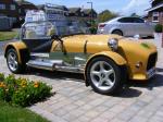
this will not be a 7esque frame. I have included a pic of my go-cart inspired locost.
As you can see there is some frame geometry that needs to be worked out. The frame will be two rails that run from the front wheel to the rear alxe
with cross members in between.
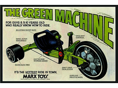 
Rescued attachment greenmachine2d2.jpg
|
|
|