violentblue
|
| posted on 14/3/07 at 03:49 AM |

|
|
SUSPENSION PICK UP POINTS IDEA.
I'm in the priocess of designing mu own IRS system based on Ford Thunderbird components.
the idea came while trying to figure out how to tie all 4 inner suspension pick up points together so geometry will remain constant., but the diff is
in the way for any strait line between any 2 points.
I was thinking that the best way to reduce the issues of movement while welding of something as critical as suspension pick up points would be to tie
all four inner pick up points to a single plate. not possible with tubes in this case.l
Let me explain. I'm designing the suspension in cad, I could easily take this infomation and plot out ay 1:1 my inner points on the xz axis,
transfer this to whatever guage metal would be appropriate, center punch and drill, and clearance for the diff, and chassis attachment points.
do this x4 and as long as I use same inner width for my upper and lower a arms, I have my suspension laid out and unlikely to move while welding, at
least in relation to one and other.
Understand my meaning?
your thoughts?
[Edited on 14/3/07 by violentblue]
a few pics of my other projects
|
|
|
|
|
violentblue
|
| posted on 14/3/07 at 03:56 AM |

|
|
if this works well I might just do something similar for the front end.
a few pics of my other projects
|
|
|
violentblue
|
| posted on 14/3/07 at 04:17 AM |

|
|
incase my rambing incoherent post was confusing, a plate like this

[Edited on 14/3/07 by violentblue]
a few pics of my other projects
|
|
|
nitram38
|
| posted on 14/3/07 at 07:31 AM |

|
|
On the plus side, it will be very accurate. On the negative side it is adding extra weight.
This is similar setup to formula cars except they use the engine/transmission as a stressed member instead of a chassis.
|
|
|
3GEComponents
|
| posted on 14/3/07 at 03:33 PM |

|
|
You want to look at that bike engined kit that looks like an Atom (can't for the life of me remember it's name now), that does that at the
front.
|
|
|
Wadders
|
| posted on 14/3/07 at 04:40 PM |

|
|
Is this what you mean? Chap on pistonheads building a middy btw, can't image he'd mind me linking to the pic.
As you might guess the ply will be replaced with ally 

[Edited on 14/3/07 by Wadders]
|
|
|
MikeRJ
|
| posted on 14/3/07 at 04:48 PM |

|
|
It would certainly allow very accurate placement of suspension mountings, but if made from 3mm steel (which is what standard locost brackets are), it
could be a bit heavy IMO.
|
|
|
Tralfaz
|
| posted on 14/3/07 at 06:38 PM |

|
|
You might consider making one and using it as a fixture to hold traditional brackets in place for welding. Simply bolt the brackets to the plate, weld
them and remove the plate. All the accuracy without the weight, and you would only have to make one.
T
|
|
|
chrisg
|
| posted on 14/3/07 at 06:45 PM |

|
|
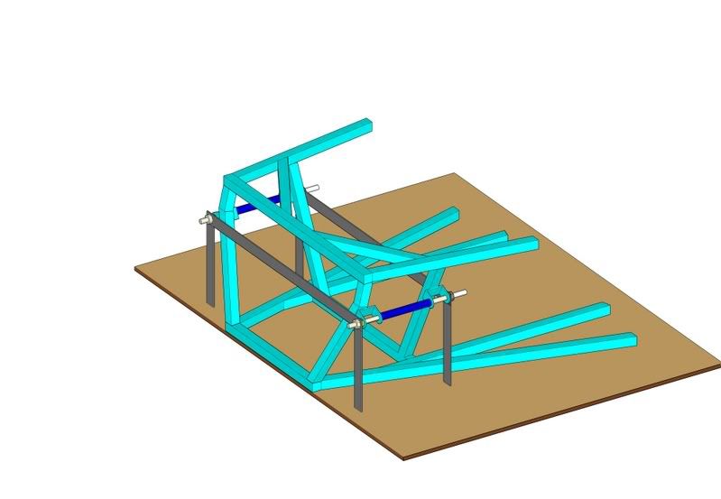
The new book (he said, blowing his own trumpet) has jigs for exact positioning of the brackets, like this:-

All the dimensions are in the book
Cheers
Chris
|
|
|
violentblue
|
| posted on 14/3/07 at 07:59 PM |

|
|

Thats a nice looking setup, probably would be heavier than my idea in the end though, and that much alu would cost a bit.
I would use two plates for one of his, sandwiching the bushing.
a few pics of my other projects
|
|
|


