scudracer
|
 posted on 16/9/07 at 11:29 PM posted on 16/9/07 at 11:29 PM |

|
|
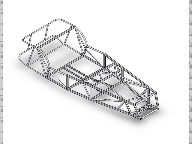
Solidworks 3D Spaceframe Progress
By a person who used to work for Lotus Engineering. Looks interesting.
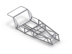 
Rescued attachment dframe 140907.jpg
Shameless-ad-supported-blog-that-belongs-to-my-friend plug - http://www.sevenbuilder.com & http://www.bikervoodoo.com
|
|
|
|
|
D Beddows
|
| posted on 17/9/07 at 07:38 AM |
|
|
Nothing new there though - it's basicaly a Caterham chassis!...........I've just done an almost identical 3D model after trawling the
internet for pictures of bare caterham chassis 
|
|
|
scudracer
|
| posted on 20/9/07 at 09:35 AM |
|
|
Yeah nothing new but it looks pretty tasty ... or will be when its complete!
Shameless-ad-supported-blog-that-belongs-to-my-friend plug - http://www.sevenbuilder.com & http://www.bikervoodoo.com
|
|
|
Paul TigerB6
|
| posted on 20/9/07 at 10:17 AM |
|
|
Might be a dumb question but where does the rear suspension fit? Take it there is the back end to do yet?
|
|
|
02GF74
|
| posted on 21/9/07 at 08:15 AM |
|
|
it is not finished is it?
what about transmission tunnel? Itsn't it going to be quite flexible round there not to mention a cage to prevent the prop whicking your legs
to a pulp sould a UJ let go?
|
|
|
scudracer
|
| posted on 23/9/07 at 11:14 AM |
|
|
Work in progress. Rear, trans tunnel tubes, brackets, bracing, etc. to be put in. Lots more work to complete.
BTW does anyone have access to a late model Caterham spaceframe chassis? Need some dimensions for the 'rear bulkhead' A (width) and B
(height) measured from inside the rectangle. From pictures on the net I presume its 3/4" square section. Thanks!

[Edited on 25/9/07 by scudracer]
Shameless-ad-supported-blog-that-belongs-to-my-friend plug - http://www.sevenbuilder.com & http://www.bikervoodoo.com
|
|
|
scudracer
|
| posted on 29/9/07 at 05:40 PM |
|
|
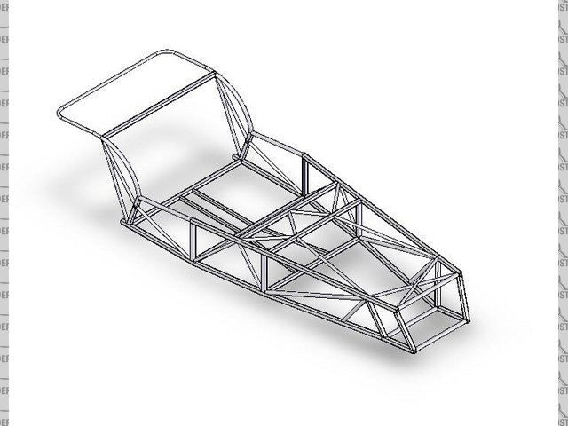
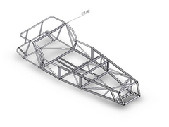
Latest update ...
Rescued attachment roadster assy 300907.jpg
Shameless-ad-supported-blog-that-belongs-to-my-friend plug - http://www.sevenbuilder.com & http://www.bikervoodoo.com
|
|
|
scudracer
|
| posted on 2/10/07 at 10:11 AM |
|
|
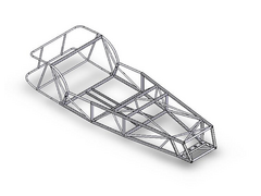
More parts added (rear and front).  Still need dimensions for 'rear bulkhead' and tunnel. Can anyone shed some light? TQ. Still need dimensions for 'rear bulkhead' and tunnel. Can anyone shed some light? TQ.
 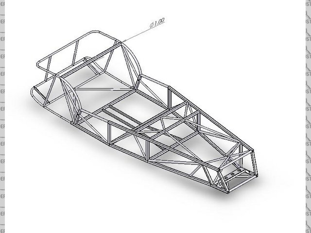
Rescued attachment roadsterassy021007.jpg
Shameless-ad-supported-blog-that-belongs-to-my-friend plug - http://www.sevenbuilder.com & http://www.bikervoodoo.com
|
|
|
mangogrooveworkshop
|
| posted on 2/10/07 at 06:45 PM |
|
|
call got all the dimms you need
[Edited on 2-10-07 by mangogrooveworkshop]
|
|
|
scudracer
|
| posted on 10/10/07 at 11:51 PM |
|
|
We are basing the centre tunnel dimensions on the Ron Champion book. Need a little more research on the front.
Shameless-ad-supported-blog-that-belongs-to-my-friend plug - http://www.sevenbuilder.com & http://www.bikervoodoo.com
|
|
|
Tralfaz
|
| posted on 11/10/07 at 12:56 AM |
|
|
[img][/img]
|
|
|
scudracer
|
| posted on 12/10/07 at 01:56 AM |
|
|
Thanks. Exactly the tubes I've wanted to do in the engine bay but not sure of the dimensions. I believe the upper \/ of the two Y sections is
made of 1/2" square tube (16ga?) and the straight lower part of the Y is 3/4" round tube.
[Edited on 12/10/07 by scudracer]
Shameless-ad-supported-blog-that-belongs-to-my-friend plug - http://www.sevenbuilder.com & http://www.bikervoodoo.com
|
|
|
Tralfaz
|
| posted on 12/10/07 at 10:42 AM |
|
|
You are correct, however the upper V's are only 1/2" because (On a Caterham) they meet 1/2" framing for the flooring support and
transmission tunnel, in your drawing I see you have a larger ( 1" ) square tube running across the chassis at the footbox, if you decide to keep
this than there is no reason not to use slightly larger than 1/2" tubing.
T
[Edited on 12/10/07 by Tralfaz]
|
|
|
scudracer
|
| posted on 12/10/07 at 11:46 AM |
|
|
Thanks Trafalz. The 1" going across needs to be modified, the centre should have a curve (to clear gearbox ...). 3/4" for the \/? Hmmm
....
Shameless-ad-supported-blog-that-belongs-to-my-friend plug - http://www.sevenbuilder.com & http://www.bikervoodoo.com
|
|
|
D Beddows
|
| posted on 12/10/07 at 11:50 PM |
|
|
I'm a little confused here! Are you trying to build an authentic looking Lotus 7 series 3/ early Caterham 7 (because that's what
you're actualy drawing, and err very slowly it has to be said  ) or do you have other more cunning plans? ) or do you have other more cunning plans?
|
|
|
Syd Bridge
|
| posted on 13/10/07 at 03:56 PM |
|
|
No confusion here Dave.
He's obviously trying to put two tubes in as many places where a single tube will do the job, whilst leaving a couple of untriangulated bits,
just to keep us all guessing! 
Cheers,
Syd.
|
|
|
scudracer
|
| posted on 14/10/07 at 11:13 PM |
|
|
The guy drawing (yes, very ... slowly) it wants it to look externally like the S2 drawing he found on the net (G. Cushing site?). That's why the
aim is not to do anything radically different. No cunning plans, nothing spectacularly different.
Powertrain - Ford Kent Crossflow 1600cc. Front uprights/brakes - Standard/Triumph/Caterham.
Syd when you say two tubes where one will do, do you mean the tube from the top of the rear top coilover mount to the lower side tube (seating
area)?
[Edited on 14/10/07 by scudracer]
Shameless-ad-supported-blog-that-belongs-to-my-friend plug - http://www.sevenbuilder.com & http://www.bikervoodoo.com
|
|
|
Tralfaz
|
| posted on 15/10/07 at 12:35 AM |
|
|
Who Knows where Syd means, and if the past is any indication he seemingly takes pleasure in being vague .
If that is the area he is referring to.... Isn't it an attempt to support the Trailing Arm mount?
[Edited on 15/10/07 by Tralfaz]
|
|
|
Alan B
|
| posted on 15/10/07 at 02:11 AM |
|
|
I think Syd is referring the the area ahead of the rear wheels marked with a red lines forming an X...one of the members would be redundant...you only
need one diagonal to fully triangulate a quadrilateral shaped opening.......
|
|
|
Tralfaz
|
| posted on 15/10/07 at 10:20 AM |
|
|
Perhaps. Though I drew the Red lines,not him.
FWIW this is what Caterham does, rather than Triangulating with a single 1" diagonal they chose to use two 1/2" tubes forming the
"x" to increase hip width, and later to allow for a 1/2" Aluminum Honeycomb side panel to be fit and still flush out with the
interior of the frame.
T
|
|
|
D Beddows
|
| posted on 15/10/07 at 11:16 AM |
|
|
They did but only on the later de dion chassis and they don't any more ... not on the CSR at least. Looking at it though I'm not sure
what the section of the tube is on the CSR - it's a thin rectangular section rather than box by the look of it
|
|
|
Tralfaz
|
| posted on 15/10/07 at 11:31 PM |
|
|
You are right, they don't use it on the new CSR chassis, and to be honest I don't know if any changes have been made recently to the
'Classic' ,'Roadsport',etc....
T
|
|
|
scudracer
|
| posted on 16/10/07 at 03:24 AM |
|
|
Do you think the 'X' shape was more for side impact protection than stiffening?
Shameless-ad-supported-blog-that-belongs-to-my-friend plug - http://www.sevenbuilder.com & http://www.bikervoodoo.com
|
|
|
D Beddows
|
| posted on 19/10/07 at 01:05 PM |
|
|
Just had another look at your friends drawing..... quite where/how is he planning to mount the trailing arm(s) just out of interest.......?
|
|
|
Echidna
|
| posted on 3/11/07 at 04:36 PM |
|
|
Does anyone has the original (not converted to .igs or something) solidworks file of this chassis?
|
NOTE:This user is registered as a LocostBuilders trader and may offer commercial services to other users
|