
F27 Owners urgent safety warning!!!
gregf27 - 4/6/06 at 07:55 PM
Went for a run in my plan built F27 on Tuesday , and as I was approaching a junction, I heard a loud "POP" and the off side front wheel
canted over and locked up.!!

On checking what had happened , the weld around the nut on the lower wishbone had snapped!!!

This has happened to at least one other F27 owner ( Bruce Jackson ) that I am aware of ,
I am sure that this could happen to anyone else with this type of designed lower wishbone.
PLEASE can the F27 owners / builders check their wishbones , and carry out the strengthening suggestions that I have just completed ( photos in my
archive )
Luckily I was travelling slowly and there were no injuries , Damage wise , I have had to replace the steering rack ,as it had pulled one of the racks
out by 20mm!! 

Luckily I had a spare rack in my garage!!
If this post helps to avoid even a single accident or injury then I will feel good!!
I'll try to post a pic or two now!
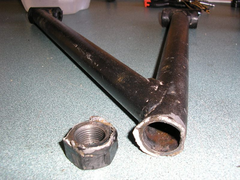

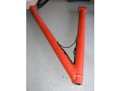
F27 lower wishbone snapped
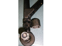

F27 wishbone strengthening par
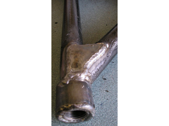

F27 wishbone underneath
ChrisGamlin - 4/6/06 at 08:05 PM
Jesus thats scary, I cant believe they just welded on a bolt like that! 
omega 24 v6 - 4/6/06 at 08:15 PM
Looks like a severe lack of penetration. I wonder what the rest of the welding is like


Confused but excited. - 4/6/06 at 08:25 PM
Jeez! How scary is that?
Just 'cos you bought it, obviously don't mean it's safe.
Why in hell would anyone do something so stupid!
t.j. - 4/6/06 at 08:31 PM
Who fabricated that???
I would make an insert and drill two holes which would give extra strenght.
Hopefully, the other drivers check-up their arms.
JoelP - 4/6/06 at 08:31 PM
never heard of a threaded insert i guess!  thats some bleak stuff...
aerobrick - 4/6/06 at 08:32 PM
Jesus I am just about to assemble my f27 suspension its all new in the box looking at that failure i will have a really good look
May even post a photo on here showing what the bought new from YKC before don sold the whole shebang Last year.
I will be modding mine I simply do not like the way its designed.
Jon Ison - 4/6/06 at 08:32 PM
I must say the weld looks a bit dodgy but the idea is even more dodgy, that's a very highly stressed area of any car.........


DIY Si - 4/6/06 at 08:42 PM
Weld looks to have barely attched the nut to the bone tube. There is surely a better way to make these things? Just out of curiousity, how do the
inserts weld in? I've never seen one up close before.
MikeRJ - 4/6/06 at 08:53 PM
quote:
Originally posted by gregf27


F27 wishbone underneath
Your going to have to remove a lot of that outer weld to get a flat surface for the lock nut to seat against. I'd be tempted to drill a couple
of holes though the side of the tube and put some plug welds in for extra security. A proper threaded insert would be better again.
ChrisGamlin - 4/6/06 at 08:55 PM
A much better way to do it would be to make up a long threaded insert that would support the entire length of the ball joint, then slide that inside
the tube and weld it in. You'd probably puddle weld it in as well so its welded at both ends of the tube.
DIY Si - 4/6/06 at 09:13 PM
So, do you buy the inserts or make them? Never treid to find any before. Would you normally put plug welds down the length of them or not?
JoelP - 4/6/06 at 09:19 PM
you can make or buy them, id buy them myself as i dont have a lathe to make them on. Nick skidmore has in the past made them, i hope to buy a
selection and some roses off him 
Deckman001 - 4/6/06 at 09:37 PM
Isn't that the way Gts offer for wishbone design(Adjustable Insert) Sounds like he is ahead of the game 
Jason
nitram38 - 4/6/06 at 09:56 PM
For my bones I used 30mm long 20mm dia 1/2" UNF bushes.
Instead of them being welded onto the end of tube, my tubes meet either side of the bush. This means that the surface area of the weld is the full
length of the bush. Also a small piece of 10mm tube is triangulated between the 2 joining tubes.
[img][/img]
Liam - 4/6/06 at 10:53 PM
Hello...
Forgive me for being critical, but I dont think that strengthening is going to do a thing! The weak point is still exactly the same as it was before
- where a nut is welded onto the end of a tube. That plate may help the wishbone as a whole but wont help the weld that failed at all. And the
sleeve over the two nuts also wont help the weak weld - the inner weld of that sleeve is simply on top of the weld that failed. No part of that
strengthening has actually strengthened that original weld imho. I think the only way to do it is with threaded inserts like everyone else has
suggested.
Liam
[Edited on 4/6/06 by Liam]
JB - 5/6/06 at 04:46 AM
You will fail an SVA for a radius that is too small but something like that, which is just shocking, doesnt get picked up.
Poor penetration is not the real problem it is poor design.
Welds should never be loaded in tension (pull) but in shear. You should get as much weld surface area as possible.
Which is why you should have a threaded insert, that slots into the tube. The end of the tube is slash cut (not square). The slash cut gives more weld
area and puts the weld in shear.
A couple of rosette welds are a good idea. Rosette welds are where you put a hole in the outer tube (6mm) and weld through into the inner tube, a bit
like a big spot weld.
John
britishtrident - 5/6/06 at 06:52 AM
I don't think the mod hs fully addressed the reall cause of the failure
Personally I would have used a long threaded insert bronze welled/brazed in or used thick wall tube and tapped the thread on to the tube as per book
Locost top wishbone..
[Edited on 5/6/06 by britishtrident]
Hellfire - 5/6/06 at 08:13 AM
I'd say poor design too...
How the hell a nut welded onto the end of a pipe is supposed to support anything like a suspension component is beyond me.
Either a insert brazed in or even pinned is better than the option used. A severe redesign is vital to prevent this happening in the future. As a
critical part you would expect nothing less really...
nitram38 - 5/6/06 at 09:39 AM
Not a very good picture, but it shows how I cut half of the tube away and welded the bush in. On my outboard joints, both tubes meet each side of the
bush, but with enough gap to weld all 3 componants. Please ignore the nut cover/lock wire, it is for my up coming sva.
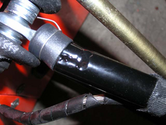

Description
[Edited on 5/6/2006 by nitram38]
David Jenkins - 5/6/06 at 09:44 AM
quote:
Originally posted by Hellfire
I'd say poor design too...
How the hell a nut welded onto the end of a pipe is supposed to support anything like a suspension component is beyond me.
Either a insert brazed in or even pinned is better than the option used. A severe redesign is vital to prevent this happening in the future. As a
critical part you would expect nothing less really...
I was surprised to see the same technique used by a so-called top hot-rod builder in a programme on Sky - they were making the rear swinging arms by
welding nuts onto the end of steel tube. A few tack welds, fit the rose joints, try them for size, then strip down and fully weld. If I was paying
over $50000 for a car I'd expect better engineering than that!
David
P.S. It wasn't American Hotrod - it was some other show.
DarrenW - 5/6/06 at 10:00 AM
Defo bad design. Nitram has the better idea of sandwiching the 2 wishbone tubes either side of a threaded insert and fully welding.
My lower 'bone takes the lower ball joint that bolts onto a plate. Not as adjustable but defo stronger.
Its amazing what some people offer for sale!
JB - 5/6/06 at 10:14 AM
Quote"I was surprised to see the same technique used by a so-called top hot-rod builder in a programme on Sky"
Doesnt surprise me. Unfortunately a lot of hot rodders are also ignorant of good design. They can build big engines, craft nice looking pieces of
metal and have great paint jobs but fundamental good design is often lacking.
John
britishtrident - 5/6/06 at 11:23 AM
Some 20 years ago I remember looking at a Rover V8 powerer T bucket Hot rod. To get the steering coloumn to clear the engine the bulider had used a
Viva steering rack mounted off centre by about 200mm from the vehicle centreline and one track rod was extended in length to accomodate this. What
really irked me was the driver and I presume builder of the Hot Rod was acting as a RAC MSA assisant scrutineer.
pewe - 5/6/06 at 11:26 AM
Greg. that's a bug*er I've not long had mine done by my local pro. welder. Must say he wasn't over-keen to do it that way though - same
as JB's comments about shear rather than tension. Suppose I'll have to find some inserts - one step forward and two back as usual!
Cheers for posting it - I thought Bruce's was a one-off, Pewe.
02GF74 - 5/6/06 at 02:46 PM
thanks to y'all (especailly Darren) for pointing this one out - need to have a look at my ones
From memory the lower ball joint is transit - do I need to get a threaded tube and weld it inside the lower tube or is there some other (simpler but
not necessarily cheaper) solution?
DarrenW - 5/6/06 at 03:12 PM
iirc my lower bone uses the ball joint from a Maxi which is bolted onto a plate - ie doesnt use the threaded insert / nut. Ive no idea how you'd
convert a F27 bone to do that though ref geometry etc.
pewe - 5/6/06 at 03:24 PM
F27 owners club reckon only 2 like this in 12 years - but doesn't help those 2 owners. I reckon I'll put a strap top and bottom of the nut
sides and rosette weld there and then back onto the wishbone tube. Current F27 marque owner Peter Allan of Image Sports Cars reckons they have
re-desingned the bottom wisbone so it sandwiches the ball joint pick-up tube. Cheers, Pewe 
02GF74 - 5/6/06 at 03:31 PM
quote:
Originally posted by pewe
F27 owners club reckon only 2 like this in 12 years
bear in mind that is 2 owners that lived to tale the tail; not sure how information about those that didn't would get publicised......
MikeRJ - 5/6/06 at 03:42 PM
If it uses the transit drag link (as per locost top wishbone), then it shouldn't be too difficult to rebuild the wishbones using the threaded
tube available from Lolocost and probably many of the other Locost suppliers.
pewe - 5/6/06 at 03:44 PM
yep, you're right that's why I'm going for a belt & braces fix. Cheers, Pewe
gregf27 - 5/6/06 at 10:28 PM
I'm glad that my mishap has raised awareness!!
bit worried that my attempt to strengthen it was poo pood!!,
before I put it back on the road I want to make sure its 100% safe - I drive my little boy round in it mostly.
I have got hold of a newer set of wishbones , that have the threaded insert welded in,
Do you think this will be ok?, or should I put a strengthening bar accross the two arms, to make a bit of a triangle?,
Your comments please!!
Greg
[img][/img]
Liam - 5/6/06 at 10:49 PM
That looks a hell of a lot better!
By a bar accross the two arms to form a triangle, do you mean right near the bushes? No point at all as far as i'm concerned. The chassis does
that job for you. I've seen that caterhams have a very thin tube on there wishbones in this location, and the only possible reason for it that i
can see is to stop the wishbone pulling in during welding. In fact I wish i was aware of this when I made my bones! As it is, that's an elegant
and pure wishbone - no bits of plate causing stress concentrations, nothing applying bending loads, and the minimum possible welding. I'd say
leave it like that, it should be fine.
Liam
[Edited on 5/6/06 by Liam]
Avoneer - 5/6/06 at 10:49 PM
I'd be tempted to put a 6mm plate gusset with a curved edge in there welded to the inside edges of each arm (not top or bottom)
Crap pic I know, but you should get the idea.
Pat...

Rescued attachment 1.jpg
Liam - 5/6/06 at 11:03 PM
Wouldn't bother with that myself. If you're mounting a shock or plate mounted ball joint then yeah, but otherwise it wont help. It's
already an ideal structure with straight members directly linking the nodes. A plate will just apply stress concentration and bending to the tubes
where it ends, and the welding wont do any good either. All imho of course.
Liam
nitram38 - 5/6/06 at 11:38 PM
Compared to my car, your bones are much shorter than mine.
Because mine is a single seater design, the body is the width of one person, so my bones are very long.
My triangulation is because of this. On short bones, I would not bother with triangulation, but it would not cause any harm to do so.
Looking at the bush though, is it just a butted seam weld around the end of the bush or does the bush extend further into the tube?
If it is just a butt weld, it is much better than the originals, but I would have made a longer bush and cut half of the tube away and then welded
the bush in.
This would create two half moon welds (which equal your butt weld) but also two logitudinal welds that run the length of the bush.
This would create two different opposing shears and this will make the joint stronger.
Take a look at my earlier photo.
[Edited on 5/6/2006 by nitram38]
907 - 6/6/06 at 12:09 AM
Hi All
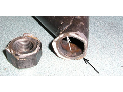
It looks to me as if part of the weld has been broken for some time.
The silver areas are newly fractured metal.
The brown areas, arrowed, are old cracks. (IMHO)
I would like to know what grade of nut this is.
Possibly a high tensile, higher carbon content? This could explain the fracture.
Paul G

Rescued attachment wishbone2smls.jpg
MikeRJ - 6/6/06 at 12:31 AM
quote:
Originally posted by Liam
Wouldn't bother with that myself. I
Me either, the newer bones look infinitely better designed. No need for any gussets etc. IMO.
JB - 6/6/06 at 04:56 AM
If you do want to put a gusset in then it would be better on the top or bottom as the weld is then is shear.
But as mentioned previously the structure would not then be a perfect triangle and put in bending loads.
A wrap around finger plate would be a good idea. I know the picture shows the other end of a wishbone but it is the best picture I could find!
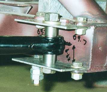
Please note this picture was taken during construction and is a mock up for build purposes.
If you want to see some top class wishbones try to get to a British round of the hillclimb championship and check out a Gould. You will not find
anything on these cars that is not structurally well designed.
John
pewe - 6/6/06 at 08:29 AM
Steve Porter who owned F27 reckons that factory cars built within the last 8/9 years have threaded inserts. Also mine are triangulated near the
chassis pick-ups by 12mm diam tube - if it's good enough for Caterham it's good enough for me and I don't believe they put their brace
there to facilitate welding.
Chers, Pewe
iank - 6/6/06 at 09:13 AM
quote:
Originally posted by pewe
...
Also mine are triangulated near the chassis pick-ups by 12mm diam tube - if it's good enough for Caterham it's good enough for me and I
don't believe they put their brace there to facilitate welding.
Chers, Pewe
I'd guess a brace at the chassis pickups is an attempt to reduce fatigue failures. A wishbone made from two arms without it will try to splay
slightly as the wheel is pushed towards the car. Since there are relatively soft bushes between the wishbone and the solid chassis brackets there
will be a very small bending force at the welded joint allowed as it isn't a perfectly rigid triangle. If there is any kind of crack or weakness
at the welded join it will eventually fail.
britishtrident - 6/6/06 at 12:42 PM
More likely it is just to keep the distance between the wishbones eys in spec durring manufacture and storage.
Nisseven - 7/6/06 at 11:02 AM
That 12mm brace has been recomended to me by a person I have great respect for as an engineer. As has already been mentioned it stops the slight
splaying on the wishbone onder loading due to the compliance of the bushes.
Also IMHO even that new wishbone is pretty ugly for something produced commercially. The mig welding is not pretty and at least it should have been
tigged.
Bruce


 thats some bleak stuff...


