midge
|
| posted on 1/10/07 at 02:27 PM |

|
|
Alternator wiring
Can anyone assist? My alternator (Focus freebie) has a 2 large terminal connections (linked) another smaller connection and a separate b+
connection. The Rapidfit loom has a large brown wire and small brown / yellow warning light wire. Which goes where?? Got the feeling I'm
missing one wire.
Cheers
Steve
|
|
|
|
|
VinceGledhill
|
| posted on 1/10/07 at 02:48 PM |

|
|
Presuming your wiring loom is the UK colours then the brown is the feed from the battery. They are usually terminated at the starter motor.
The reason you have two large terminals is because of the current that can be outputted by the alternator can burn out just one.
Simply get two terminals and solder them both onto the end of the cable. Picture a letter h with the stick being the cable and the two bottom bits
being the terminals.
Presuming that the yellow goes to the other smaller terminal. If you touch it to earth on the alternator with the ignition swiched on the light
should come on. If this is the case then that's deffinately where it goes.
Then again I could be completely off the mark. Focus freebie, I don't really know but just re-reading your post it sounds like the B+ is
battery. Would help if you had a picture of the alternator.
Regards
Vince Gledhill
Time Served Auto Electrician
Lucas Leeds 1979-1983
|
|
|
02GF74
|
| posted on 1/10/07 at 03:33 PM |

|
|
i'd be cautious about this.
I assum you have wiring diagram fro the loom and understand it?
I have posted in the past, at least twice, the contact deisgnations for alternator so please search.
B+ is charge output
W is warming lamp
ther maybe one or 2 others.
soldering wires together, hmmmm.. first they need to have good electrical contact so the way I would do it is to put two crimp eyelet connectors and
botl them onto the stuff.
if you really feel you must use solder, then untwsit the wires to splay the strand out and twist them together to the stranfs intermingle, apply flux
and then solder.
|
|
|
midge
|
| posted on 2/10/07 at 11:55 AM |

|
|
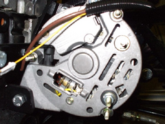
Thanks for your thoughts. I'm still not sure on the best way forward. The photo shows my problem.
Steve
 
Rescued attachment Alternator.JPG
|
|
|


