R1 engine position (opinions sought pls)
dern - 12/2/05 at 05:10 PM
Afternoon,
I took delivery of my MNR manifold and sprocket adapter yesterday so set about trying to position the engine in the chassis.
I had already (rather rashly) put the tranmission tunnel in but moving the right side isn't an issue.
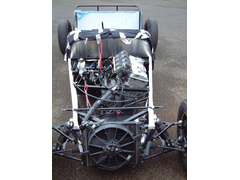
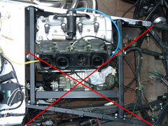
However, I'm seeking advice as to whether or not my proposed engine position is ok or not...
I've raised the chassis off the floor by one inch and the engine is sitting flat on the floor. Is that too low or too high?
It's pretty close to the outside top rail but I think I could get away with it.
The prop won't be dead central to the transmission tunnel but the engine half won't run parallel to the tunnel but make its way to the
center of the tunnel for the middle prop joint. My assumption is that as long as the output shaft from the engine and the input shaft to the diff are
parallel then that's all that matters... is that right?
On the following pictures the line of the output shaft is shown with a piece of box bolted to the sprocket adapter although the prop won't take
that path (see above) it helps me make sure the output shaft is parallel to the chassis.
Here's some pictures...


I think I'm going to use a foam filter sticking out of the bonnet (unless anyone has a better suggestion). What happens when it rains though?
I'm going to chop up the coolant pipes that come out of the top of the head and go to the thermostat housing so that the pipes run flush along
the head.
Any suggestions or comments are gratefully received.
Thanks,
Mark
Jasper - 12/2/05 at 05:14 PM
Looks good to me 
dern - 12/2/05 at 05:17 PM
Thanks Jasper.
As an aside, does anyone have some picture of BEC engine mounts (not a cradle) I can, erm, be inspired by? 
Cheers,
Mark
adamhay - 12/2/05 at 06:05 PM
This is mine - scan through the gallery.....
http://client.webshots.com/photo/265479901/265479901UHiIzv
Peteff - 12/2/05 at 06:40 PM
Shouldn't the line where the sump joins be parallel to the floor? If it's angled up a bit more you may be able to align it with your tunnel
without much chopping about. What happens when it rains though? It gets wet I suppose 
[Edited on 12/2/05 by Peteff]
dern - 12/2/05 at 07:19 PM
quote:
Originally posted by Peteff
Shouldn't the line where the sump joins be parallel to the floor? If it's angled up a bit more you may be able to align it with your tunnel
without much chopping about. What happens when it rains though? It gets wet I suppose 
The conclusion of
this thread was that the bottom of the sump should be parallel to the floor. Mine
isn't precisely parallel to the floor due to those little feet you can see to the right of the sump in picture two but it's as near as
damnit.
What I meant when I mentioned the rain was wether or not having the filter sticking through the bonnet would cause water to be sucked in to the engine
or not?
Regards,
Mark
[Edited on 12/2/05 by dern]
Wadders - 12/2/05 at 07:43 PM
No problems to report, even in the heaviest of downpours.
Al.
What I meant when I mentioned the rain was wether or not having the filter sticking through the bonnet would cause water to be sucked in to the engine
or not?
Peteff - 12/2/05 at 07:44 PM
Yes, the cutaway diagram shows it well. The pickup is parallel to the base of the sump. On the filter, engines should run better on moisture laden air
as it is denser. Unless you are absolutely drowning it shouldn't be any different to any of the other locost type cars running round with exposed
filters. I wouldn't worry too much about it.
Hellfire - 12/2/05 at 07:47 PM
I think Pete has a point here. The engine is designed to run parallel in the bike engine. Therefore, as Pete says the sump/engine joint should be
horizontal in any event. Our ZX12R engine has a wickedly shaped sump so levelling it would be impossible.
IMHO the engine when viewed from the front is too clockwise, and too high. Personally I'd level up the joint first, then bolt on the prop to
ensure you gain enough clearance in the tunnel. By relying on that box section for a make-shift prop isn't going to guarantee you clearance you
require. Once that is done you could make temporary fittings to make sure your engine fits under your bonnet, you can always chop the sump...
it'd look a bit unsightly having the cam covers pocking through the bonnet aswell as the filter...
Plan well, well ahead for this one...
mangogrooveworkshop - 12/2/05 at 10:40 PM

[Edited on 12-2-05 by mangogrooveworkshop]


Rescued attachment r1 mount.jpg
mangogrooveworkshop - 12/2/05 at 10:42 PM


dern - 12/2/05 at 10:44 PM
Thanks guys.
I'll be using a foam filter out of the bonnet then and won't worry about it.
The pictures of the engine mounts are great, cheers.
I've emailed MNR to ask their advice about engine orientation. My gut instinct is to mount the engine as it is in the bike which is with the base
of the sump parallel to the ground but I hear what people are saying.
All good fun though eh? 
Mark
Jasper - 13/2/05 at 10:08 AM
I would go for parallel sump, and I wouldn't wont any more than an inch below the bottom rail. I seriously recommend a sump guard too under that
(which will add an extra 1/2 inch) as I have regularly ground mine out on speed bump etc.
I went for a simple but easy cradle system which unbolts.


Rescued attachment enginebaysm.jpg
ChrisGamlin - 13/2/05 at 12:05 PM
Mangroove, I think that one is Richard Miles's Striker, I recognise the huge ACB10 rear tyres he had on it 
phelpsa - 13/2/05 at 12:50 PM
quote:
Originally posted by mangogrooveworkshop

[Edited on 12-2-05 by mangogrooveworkshop]
Thats what I'm doing.
phelpsa - 13/2/05 at 12:52 PM
[img]http://www.locostbuilders.co.uk/viewthread.php?action=attachment&tid=22395&pid=180793[/img]
Bob C - 13/2/05 at 01:13 PM
If you want to mount the engine on rubber you might want a peek in my photo archive, eg.
http://www.locostbuilders.co.uk/photos.php?action=showphoto&photo=engmntfr.jpg
All in all not much different to the others but might be a bit comfier!
cheers
Bob
dern - 13/2/05 at 08:02 PM
quote:
Originally posted by Hellfire
I think Pete has a point here. The engine is designed to run parallel in the bike engine. Therefore, as Pete says the sump/engine joint should be
horizontal in any event. Our ZX12R engine has a wickedly shaped sump so levelling it would be impossible.
IMHO the engine when viewed from the front is too clockwise, and too high. Personally I'd level up the joint first, then bolt on the prop to
ensure you gain enough clearance in the tunnel.
Word back from MNR... the base of the sump should be level and not the sump/crankcase join.
Cheers,
Mark
Stu16v - 13/2/05 at 08:46 PM
...as it is in the bike... 
ChrisGamlin - 13/2/05 at 10:22 PM
To be perfectly honest, I dont reckon it would make much difference within a couple of degrees, if you think about it, in the bike the engine will go
through quite a few different for/aft angles depending on braking, accelerating, whether there's a pillion on the back etc etc. having said that
obviously the ultimate goal is to make sure that the oil pickup is horizontal so the oil doesnt flow away from it in either direction, so Id go along
with the consensus that it should be as it sits on the ground with the base of the sump horizontal, and to ignore the line of the sump gasket.
[Edited on 13/2/05 by ChrisGamlin]
Rorty - 14/2/05 at 04:02 AM
I would agree with CG; a couple of degrees either way won't make any difference.
BTW, does anyone have accurate dimensions of the R1 engine, particularly the mounting points?
ChrisGamlin - 14/2/05 at 09:40 AM
I only got my engine last week but will measure it up at some point, Im not sure how accurate I can do it tho, whats the best method?
Rorty - 14/2/05 at 11:47 AM
quote:
Originally posted by ChrisGamlin
I only got my engine last week but will measure it up at some point, Im not sure how accurate I can do it tho, whats the best method?
In the absence of a decent CMM  , the best method is to set the engine on a board with two straight lines drawn on it, at right angles to eachother.
It doesn't matter if the engine is not central, though it is important to make sure the cases are parallel to one of the lines. I would remove
one of the side covers and use a set square to get the engine level and parallel to a line. When the engine's perfectly level in the X & Y
planes and then use a series of set squares and steel rulers to establish all the points. I normally pick the bottom rear mounting hole as the datum
and take all other measurements from there. Don't forget to plot the centre of the sprocket too.
If I were closer, I would give you a hand; I don't have a CMM, but I do have a bunch of height and surface gauges which make the job easier.
I'd also buy you beer.
Coose - 15/2/05 at 09:18 PM
Have a look here....
http://www.ne7ers.co.uk/modules.php?set_albumName=albun01&op=modload&name=Gallery&file=index&include=view_album.php
The mountings aren't finished in these pics, where I've added a vertical to each of the rears, and a diagonal from the top left to the
bottom right (in relation to the engine position). I'll stick some more pics on there once I get chance!
ChrisGamlin - 15/2/05 at 10:07 PM
Coose, is that a set of flatslides on your engine? Is it a tuned lump then?
dern - 15/2/05 at 10:36 PM
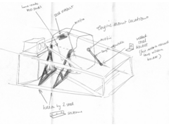
I've been out in the garage having a think and for the right hand side I was thinking along the lines of this...

The bar is inch box. The mounts to the engine are 3mm plate welded to the bar. The end mounts are 3mm plate welding to the chassis and then bolted to
the bar. The hole in the bar ends will have a bit of tube welded in to stop any possibility or crushing or the hole being worn larger.
My thinking is that that would be lighter than having tubes running everywhere, not intrude on the space where the steering column would go so I
wouldn't have to worry about clashes and also be removeable so the engine can be easily removed. It would resist the engine twisting about the
z-axis and from shifting from side to side and backwards and forwards.
I haven't really thought about the mounts of the other side of the engine.
Please feel free to point out the flaws 
Thanks,
Mark
[Edited on 15/2/05 by dern]
Coose - 18/2/05 at 09:52 AM
Chris - yep, that's a luvly set of 41FCR flatslides you can see there, but as far as I know the motor is stock.....
It'll be running on stock (TTS jet-kitted) carbs at first, then the flatslides may just get lobbed on! 
I did a deal with a sidecar racer for one of his spare engines and the carbs were part of the bartering process!
ChrisGamlin - 18/2/05 at 11:07 AM
Nice! Wish me luck with my nice complicated throttle bodies! 
Coose - 18/2/05 at 12:12 PM
Ahhh, you'll be right! Just make sure you use the R1 fuel pump to keep things simple, and get yerself a Power Commander or similar. It makes life
sooooo simple when you can download whatever program you need from their website and then off you go! 
ChrisGamlin - 18/2/05 at 12:24 PM
Yup, got myself a Power Commander PCIIIr today (the one that does ignition and fuelling), and hopefully in the process of getting a pump. Will then
run a low pressure pump up to a big swirl pot with the bike pump submerged in it, that way I don't need to mod my existing tank as its got a
return feed already.
ChrisGamlin - 18/2/05 at 01:12 PM
You may want to look at making up a cradle something like this


Alternative Cradle Design
I hope Wadders doesnt mind me nicking and editing his picture, it was the first BEC engine from above I could find 
A diagonal X frame is how Westfield do it in their BECs, I think its a good design as the X bracing will add some more strength to the chassis
compared to a ST type cradle or individual mounts.
Chris
[Edited on 18/2/05 by ChrisGamlin]
chrisf - 18/2/05 at 02:03 PM
I did mine exactly like Chris just showed. Mine is hard mounted in the corners for extra bracing but rubber mounted on the engine. I made mine out of
3/4" square. It seems really sturdy but is something I will keep my eye one.
Pics are on my website.
--Chris
ChrisGamlin - 18/2/05 at 02:39 PM
I think the Westie one is only 3/4" round tube so yours should be fine too.
Some trick rear dampers youve got there 
dern - 25/2/05 at 09:22 AM
I've been moving along on this making up some brackets and so on but on the gearbox side are two mounts where the back of the engine fits into
the frame. I've used to top mount but not (so far) the bottom one. I'm pretty happy that the engine will be firmly located without the
bottom mount but wondered if, by not using it, I'd be putting the engine under undue stress.
Does everyone else use both top and bottom mounts on the gearbox side?
Thanks,
Mark
ChrisGamlin - 25/2/05 at 09:32 AM
I never had bottom mounts on my blade but then the ST frame is quite chunkily built and holds the engine OK. Im going to build an X frame like above
for the R1 which won't be as solid so I will put on bottom mounts too
dern - 25/2/05 at 09:40 AM
quote:
Originally posted by ChrisGamlin
I never had bottom mounts on my blade but then the ST frame is quite chunkily built and holds the engine OK. Im going to build an X frame like above
for the R1 which won't be as solid so I will put on bottom mounts too
It certainly doesn't look as though the engine requires it in
order to to distort/twist (not in the chassis but as a unit) and I believe that the engine acts as effectively part of the chassis in a bike. I think
I'll do the mounts as I'm planning (without the lower mounts) and see how I feel when I'm done.
Cheers,
Mark
ChrisGamlin - 25/2/05 at 10:10 AM
Yup, you dont need it to protect the engine at all, just to stop it moving in the chassis when under load, trying to twist the frame. Basically if you
can make your frame strong enough whilst keeping it light then there's no reason to use em.
[Edited on 25/2/05 by ChrisGamlin]


