Im mounting up the speedo sensor. As Im sure you 'Busa boys know when viewed from the end its round with a flat on one side.
My question is this:- Do the magnets on the prop shaft have to rotate past this flat to make a reading? Or can they rotate past the end? If the former
how do you mount the sensor close enough to the magnets? I can mount it so that that its effectively pointing at the shaft no problem but I suspect
that this isnt how its supposed to fit!
[Edited on 12/5/08 by iiyama]
If it is the original 'Busa sensor I think it is hall effect and does not need a magnet, just a metal target. I took the target off my 'Busa as it is on the end of the output shaft and gets in the way of the adapter flange for the prop shaft. I'm pretty sure it was not magnetic. Any one know different?
It is indeed non magnetic. but I need to know the orientation of it in relation to the targets
So long as a flat surface of the metal target passes close to the sensor it should work okay. Let me take a look at my 'Busa manual tonight to see if it gives any tolerances. I would guess that less than 1mm would probably be okay but let me check for you!
Cheers matey!
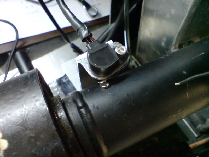
OK, heres some art. Will the sensor work in this orentation? Or do I nned to turn it through 90??
Sorry Iiyama, I couldn't find any reference to the min/max air gap between the sensor and target. Looking at your picture I don't think the
sensor will work in that position. I'm pretty sure the surface of the target must pass fairly flat to the surface of the sensor.
The orientation of bracket to shaft is fine but I think you need to reduce the 90 degree angle that you have in the mount (just before the sensor) so
that the sensor face is parallel with the target (probably about 45 degrees) when the target is closest to the sensor, and then bend the bracket to
move the sensor closer so that you have less than a 1mm gap.
Also, if I am right and it is a hall effect sensor I'm not sure if a magnet is a good idea to be used as the target as the magnet creates a
magnetic field which could generate an EMF (electromagnetic force) in the sensor.
Why not rig it up on a bench with a battery and volt meter and test it by passing a target such as a bolt head past it?
Also, have you thought about using the bolts on the input flange or output flange of the diff as your targets?
Ref your last points, yup! Have indeed looked at the output flange on the engine, but its really tight for space in that area, hence moving the sensor
down the tunnel. Hadnt thought about the diff end though so that may be a possibility.
I can glue something other then magnets to the shaft, dosent have to be magnets its just that I had them!
I'd be inclined to use existing bolts on the flanges as targets if possible to avoid adding offset weight (albeit small) to the side of the prop
shaft.
An additional benefit is that there are usually four or more bolt heads on each flange so you get more pulses and more accuracy. Also, if using the
original 'Busa clocks you should check the number of triggers (raised sections) there are on the original target disk. If my memory serves me
well I think there are 4 (but possibly 6?) so you may want to match this number of targets if possible to get the number of pulses close to the
original Busa. But you will still need a speedo corrector to adjust for the difference in final drive ratios.
Got a speed healer in line bud, figures that it would be needed come SVA. Especially as Ill be going to the concentration camp that is known as
Southampton SVA centre!
Thanks for the input!
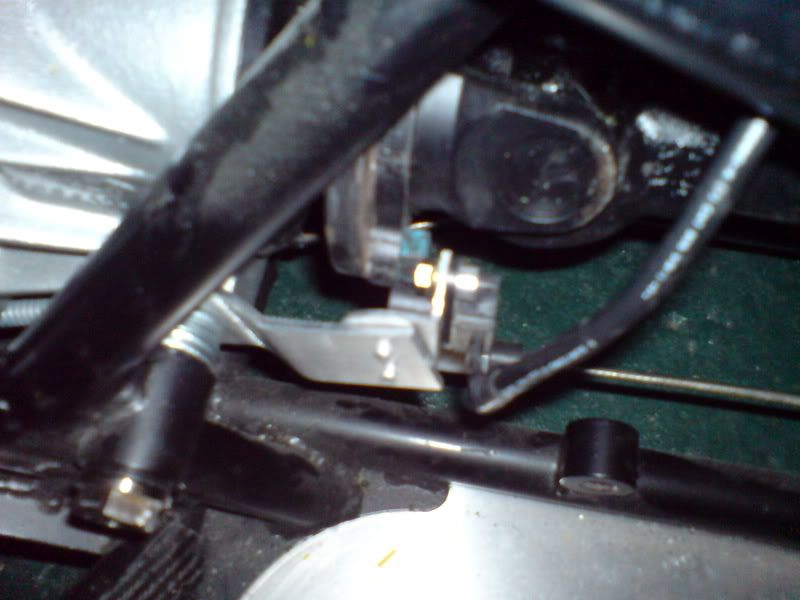
Hows this look then? Hopefully better!
quote:
Originally posted by iiyama
Hows this look then? Hopefully better!
Wouldve helped if I got the piccy in focus! 
Got 3-4mm clearance at the moment but there is a little adjustment to be had
Looks good to me!!! If a little fuzzy!!!
 Photographic skills need honing!