Avoneer
|
| posted on 29/9/05 at 10:31 PM |

|
|
Working on an easier and cheaper solution now.
Found a good place for the M8 sphericals, although not as posh as OX's, more like the gold ones I am using.
Watch this space.
Pat...
No trees were killed in the sending of this message.
However a large number of electrons were terribly inconvenienced.
|
|
|
|
|
tks
|
| posted on 1/10/05 at 01:53 PM |

|
|
mhh
i have made an gear switch system useing an electril RC Servo..
from the quarter scale section.
does anyone have ideas...if there would something an bit powerfull for it?
what would/could happen if i take out the return spring? from the gearbox..??
how much room do we have on the gear linkage, i mean what if the lever doesn't come in his rest position by an couple of degree does the
lever/box than damage extra?
how fragile is the box?
what happens witht he box if you drive normally on your bike...
but in every gear you push the lever, the bike enters gear..and you stay and you let the leaver in that pos. for 1 second...
would it sacrafise? would it become damaged? the forks??
Tks
The above comments are always meant to be from the above persons perspective.
|
|
|
Avoneer
|
| posted on 6/10/05 at 09:28 PM |

|
|
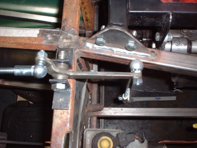
Update:
I am using this arm and all seems well, although it's a bit hard to pull the paddles.
Maybe because I've nothing to pull against like the steering wheel.
Anyone know how to mod the leverage to make the paddles lighter, but with the same movement at the gearbox end.
Pat...
Rescued attachment Top Arm.JPG
No trees were killed in the sending of this message.
However a large number of electrons were terribly inconvenienced.
|
|
|
Avoneer
|
| posted on 6/10/05 at 09:29 PM |

|
|
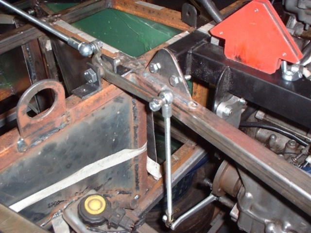
Another pic:
Rescued attachment Top Arm2.JPG
No trees were killed in the sending of this message.
However a large number of electrons were terribly inconvenienced.
|
|
|
Avoneer
|
| posted on 6/10/05 at 09:30 PM |

|
|
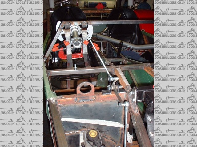
And the last pic:
Rescued attachment Top Arm3.JPG
No trees were killed in the sending of this message.
However a large number of electrons were terribly inconvenienced.
|
|
|
ChrisGamlin
|
| posted on 6/10/05 at 09:41 PM |

|
|
Hi Pat
If its all pictured in my head properly, Id say you have two options, either to lengthen the gearbox selector arm and shorten the horizontal part of
the rocker arm, that way you retain the movement whilst gaining mechanical advantage by changing the ratio between the length og the selector arm and
the length of the rocker arm
Alternatively, you could extend the vertical part of your rocker arm and shorten the distance between the pivot point and the rod connection point on
the paddles, if this is adjustable?
Chris
|
|
|
Avoneer
|
| posted on 6/10/05 at 09:59 PM |

|
|
Hi Chris,
Yep - it's really hard to visualise and work out - even with the thing in front of you.
I might wait until the steering wheel is on and then see what it's like.
It's working out a lot simpler than originally intended as well!
Pat...
No trees were killed in the sending of this message.
However a large number of electrons were terribly inconvenienced.
|
|
|
OX
|
| posted on 6/10/05 at 11:16 PM |

|
|
i think the problem is the rocker arm,,the vertical part isnt going straight up,its allready over centre .you could try just shortening the the bar
down to the gear change lever and lengthening the bar from paddle to rocker arm,,,but i would look for another rocker arm 
|
|
|
chrisf
|
| posted on 6/10/05 at 11:20 PM |

|
|
Or you could just drill a few holes on the longer arm. Attach the rod end closer and closer to the pivot until it feels better. Your throw will
lengthen but it will be easier to shift. When you find the ideal ratio, you can fabricate a new rocker--or not (I wouildn't).
--Chris
|
|
|
OX
|
| posted on 6/10/05 at 11:27 PM |

|
|
yes but the rocker arm would give a better feel if it was shaped like an L rather than _/ lmao,,wish i could explain better
|
|
|
Avoneer
|
| posted on 6/10/05 at 11:47 PM |

|
|
Hi Ox.
Now I can visualise better having all the parts, I'll have a play with a flat rectangle plate and drill loads of holes in it in different places
instead of the top rocker arm, until I come up with the perfect solution.
I'll try the "L" configuration next.
Cheers,
Pat...
No trees were killed in the sending of this message.
However a large number of electrons were terribly inconvenienced.
|
|
|
Rorty
|
| posted on 7/10/05 at 05:29 AM |

|
|
Pat, that upper lever is all wrong; wrong angle, wrong lengths.
If you think of the series of levers and paddle like this: If the levers are all the same length as the paddle (and there is zero stiction in the
lever bushes), then the effort to change gear with the paddle would be the same as if you grabbed the bike's shifter the same distance from the
shaft as your finger tips are from the paddle pivot. What's more, the tip of the paddle would move the same amount as the point on the
bike's shifter where you pushed on it.
If you made the levers all longer than the effective paddle leverage, then the effort to change with the paddle would be increased, but the tip of the
paddle wouldn't move very far.
If you made all the levers shorter than the paddle, then you would have a lighter feel to the paddle, but the tip of it would move further.
You can mix and match lever lengths, but if you want to retain a certain ratio, then you'd need to match the inputs and outputs between the
levers.
A good way to assess the required length and weight of pull on the paddle is to pull the bike's shifter at different distances from the shaft
using just your finger tips. Bear in mind that friction or stiction within the lever bushes will also add a degree of stifness.
If you're having difficulties getting your head around the set-up, I'd make the levers up roughly first from flat bar and just pivot them
on plain bolts to start with.
Drill plenty of holes in the levers for quick adjustability and try to match their lengths for consistency.
When you're happy with the feel of it all, then make it up properly and use Teflon impregnated acetal for the bushes.
Cheers, Rorty.
"Faster than a speeding Pullet".
PLEASE DON'T U2U ME IF YOU WANT A QUICK RESPONSE. TRY EMAILING ME INSTEAD!
|
|
|
Avoneer
|
| posted on 7/10/05 at 11:12 AM |

|
|
Hi Rorty,
I've been waiting patiently for you input.
Thanks, I can visualise it much better now.
Will go the "holey metal bar" route this weekend and work out how much the bike lever needs to move up and down and how much the paddle
moves and post my findings after the weekend for evaluation.
Cheers,
Pat...
No trees were killed in the sending of this message.
However a large number of electrons were terribly inconvenienced.
|
|
|
Avoneer
|
| posted on 7/10/05 at 11:14 AM |

|
|
Am I best with a straight "L" shape then?
Pat...
No trees were killed in the sending of this message.
However a large number of electrons were terribly inconvenienced.
|
|
|
chrisf
|
| posted on 7/10/05 at 11:33 AM |

|
|
Yeah, or more. I think falling rate lever system would be easiest to shift. So at full press, the angle of the rocker will be more than 90 degress.
I'd shoot for somewhere in the 60 -75 degree range. If you do it like this, the effort to shift will actually degrease as the rocker moves
through its arc.
I did the opposite on my traditional shifter and have a rising rate. Then again, my arm stregth is much more than my finger strength.
--HTH, Chris
|
|
|
Rorty
|
| posted on 7/10/05 at 02:34 PM |

|
|
I agree falling rate is desirable, but is only possible when using two separate rods for up and down changes. With separate rods, you would obviously
set the "input" side of the levers so they are at right angles to the rods at full throw.
When a single rod is used for both up and down changes, then the "input" side of the levers (everything being equal) should be positioned
at the mid point of the throw, which, unfortunately, constitutes rising rate.
There's a further point to consider: As the actuating rod is attached to one side of your paddle, one side already has a greater advantage than
the other. This means you could actually set the "input" side of the levers off centre (of the throw) to gain a falling rate for the side
of the paddle with the least advantage.
It's virtually impossible to estimate the angles, but they're achievable on paper or CAD.
As suggested before, drill plenty of holes, and as close to each other as is feasible, to make the mock up as adjustable as possible.
Rather than butchering numerous threaded rods while experimenting, you can simply set two rods alongside each other and join them together temporarily
with pairs of hose clips. When the levers and positions are all settled on, you can then cut and thread the rods to the correct length.
I commend using the proper linkage type ball joints and not clevises as the BJs are designed to reduce friction and sloppiness.
If you get the paddle action light and smooth, you'll be delighted, but if it is stiff and requires too much effort, you'll have sore
fingers/wrists and be pretty pissed off.
Sorry, that reads like a dreadful sermon, but I hope it's of some use.
Cheers, Rorty.
"Faster than a speeding Pullet".
PLEASE DON'T U2U ME IF YOU WANT A QUICK RESPONSE. TRY EMAILING ME INSTEAD!
|
|
|
Coose
|
| posted on 7/10/05 at 02:45 PM |

|
|
Mine worked first time! 
I used an equal length 90deg bell-crank, and mounted my push-me-pull-you rod about 120mm from the paddle centre pivot. I can't fault it!

[Edited on 7/10/05 by Coose]
[Edited on 7/10/05 by Coose]
Spin 'er off Well...
|
|
|
Avoneer
|
| posted on 7/10/05 at 03:36 PM |

|
|
Hi,
Cheers guys - will take all that onboard this weekend.
Coose - how much movement front to back have you got on your paddles?
Cheers,
Pat...
No trees were killed in the sending of this message.
However a large number of electrons were terribly inconvenienced.
|
|
|
Avoneer
|
| posted on 7/10/05 at 07:19 PM |

|
|
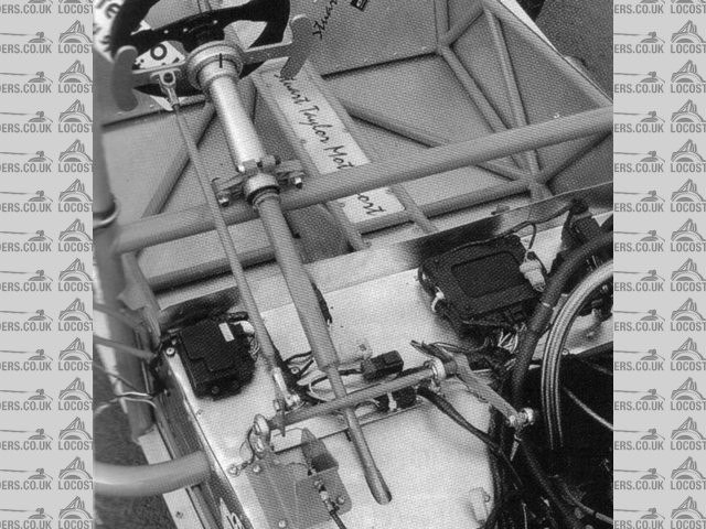
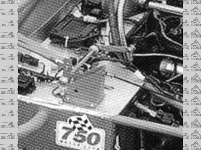
Just noticed that Stuart Taylor have more of a "tick" bell crank than an "L" - even though the two arms of the bell crank are
spread out.
Shall I have a go like this?
Pat...
Rescued attachment 1.jpg
No trees were killed in the sending of this message.
However a large number of electrons were terribly inconvenienced.
|
|
|
Avoneer
|
| posted on 7/10/05 at 07:22 PM |

|
|
And another pic:
Rescued attachment 11.jpg
No trees were killed in the sending of this message.
However a large number of electrons were terribly inconvenienced.
|
|
|
Mad Dave
|
| posted on 7/10/05 at 08:36 PM |

|
|
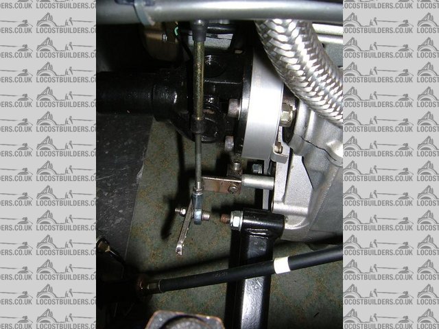
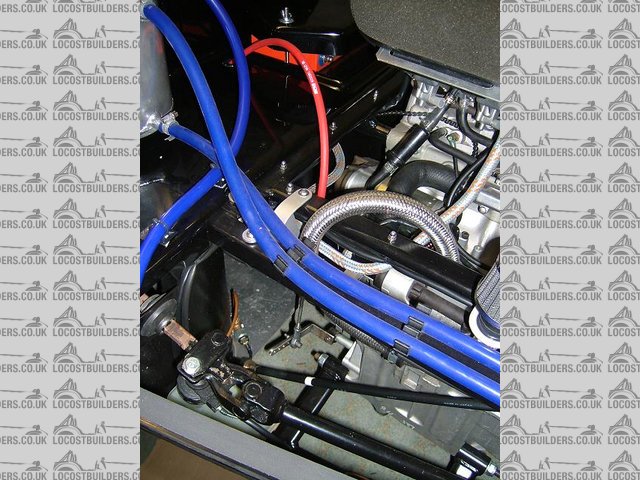
Why not used a cable, its a simple solution?
Description
Description
|
|
|
OX
|
| posted on 7/10/05 at 09:23 PM |

|
|
quote:
Originally posted by Avoneer
And another pic:
yes,,it is more of a tick shape ,,but the shape doesnt realy matter its the angles at which they are being pushed and pulled from that makes the
difference.
the bar going to the top of the rocker arm is around 90ish degrees and the bar going from the rocker arm to engine is around the 90 mark,,,,the top
arm on your rocker arm is leaning so far back that when you are pulling back on it becouse its allready so far back over centre the only way to make
it change any better would be to pull the top rocker lever down
|
|
|
Avoneer
|
| posted on 7/10/05 at 09:36 PM |

|
|
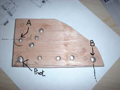
I tried with this piece of wood.
The only places I could get a proper full shift were with thejoints on A and B.
The paddles have very minimal movement and have to move the lower gear selector arm a long way.
I guess I am showing my non-engineering background here!
Pat   
Rescued attachment 1.jpg
No trees were killed in the sending of this message.
However a large number of electrons were terribly inconvenienced.
|
|
|
Avoneer
|
| posted on 7/10/05 at 09:51 PM |

|
|
quote:
Originally posted by Mad Dave
Why not used a cable, its a simple solution?
 
Description
Hi Dave,
Easy solution, but it wouldn't give me the option to increase the ratio of paddle movement to gear lever which needs increasing.
Pat...
No trees were killed in the sending of this message.
However a large number of electrons were terribly inconvenienced.
|
|
|
Rorty
|
| posted on 7/10/05 at 10:49 PM |

|
|
Mad Dave, what prevents your shift lever extension from rotating when you pull on the cable?
 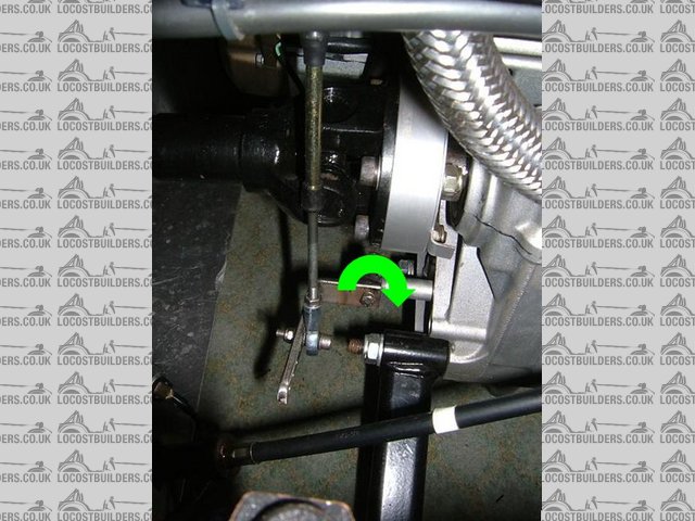
Rescued attachment Cable_end.jpg
Cheers, Rorty.
"Faster than a speeding Pullet".
PLEASE DON'T U2U ME IF YOU WANT A QUICK RESPONSE. TRY EMAILING ME INSTEAD!
|
|
|


