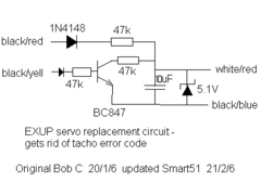
Bob C
|
| posted on 21/2/06 at 07:38 PM |

|
|
I've deleted the post with the original schematic & here's an update with Smart's mods. I've swapped his zener for a normal
1n4148 considering the voltage appearing on that input.
Bob C
 
Rescued attachment exup.GIF
|
|
|
|
|
smart51
|
| posted on 25/2/06 at 04:25 PM |

|
|
I built a nice new circuit up after all the modifications to the first one. Tested it yesterday and it was fine. Took it off and potted it in epoxy.
Went out today and the tacho was bouncing by the time I'd got to the end of the street. Lucky I'd built two then. It seemed worth while
for the cost of a few penny components.
What' the best way of weatherproofing my new circuit then?
|
|
|
Peteff
|
| posted on 25/2/06 at 05:03 PM |

|
|
Try hot melt glue on it if it doesn't heat up too much and remelt it.
yours, Pete
I went into the RSPCA office the other day. It was so small you could hardly swing a cat in there.
|
|
|
hobbsy
|
| posted on 29/8/07 at 11:43 AM |

|
|
EDIT: (vero layout) Smart51's layout is fine just need to crank the cap value to 10 mike - sorted. Going to knock one of these up tonight...
[Edited on 29/8/07 by hobbsy]
|
|
|
hobbsy
|
| posted on 19/4/09 at 09:32 PM |

|
|
Apologies for resurrecting an old thread but after building this circuit over a year ago I finally got around to fitting it a couple of days ago.
However there isn't a black and yellow wire on my 5PW EXUP connector, nearest is black and green. Also there's a blue and something wire
but I'm guessing that one is left unconnected.
I tried connecting the black and green wire to where the black and yellow goes on the schematic and I still get error code 17 
What colour wires have other people connected on the 5PW as I'm guessing its different to the 4XV but from what JimG put the same circuit works
- just need to know which wires...
[Edited on 19/4/09 by hobbsy]
|
|
|


