b14wrc
|
 posted on 15/1/13 at 09:16 PM posted on 15/1/13 at 09:16 PM |

|
|
Rear suspension
Hi all,
Just wanted to share my progress with rear suspension.
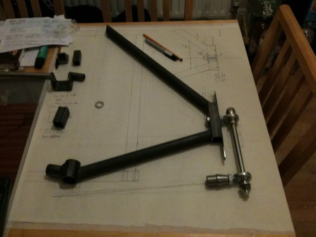
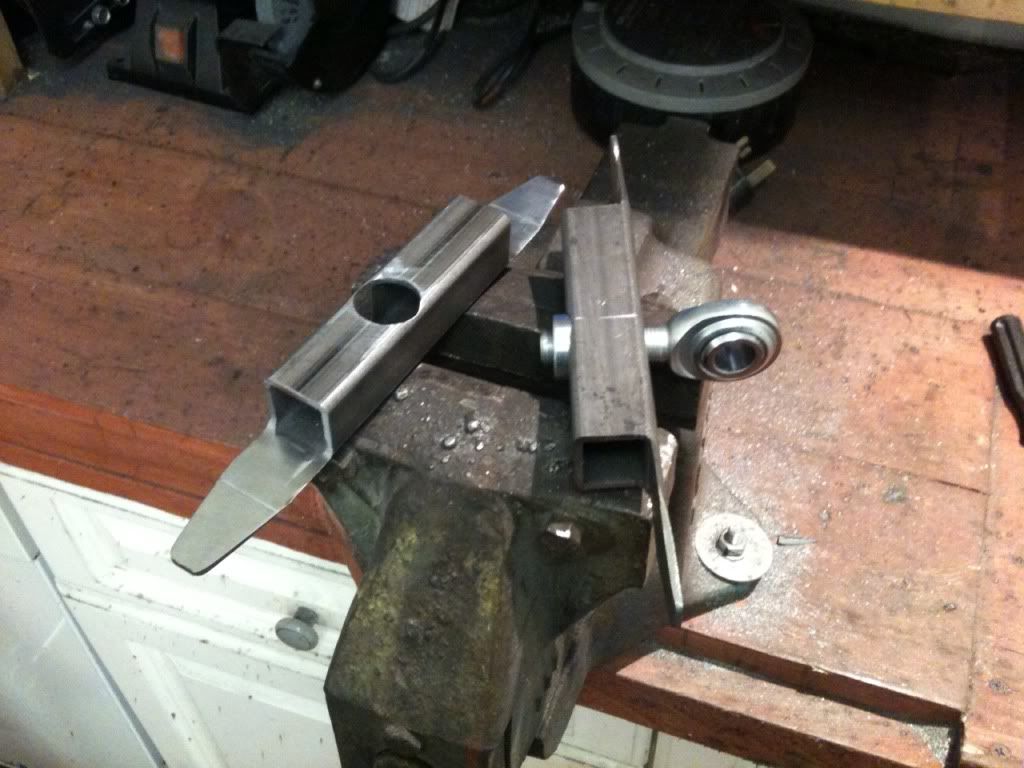
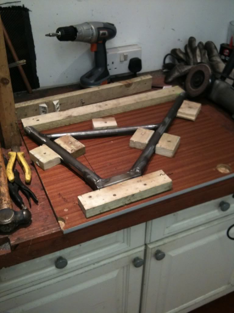
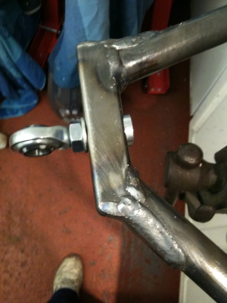
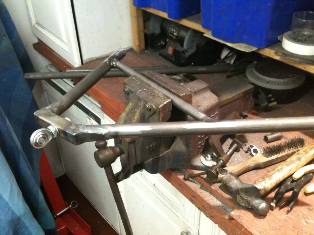
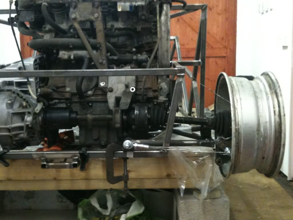
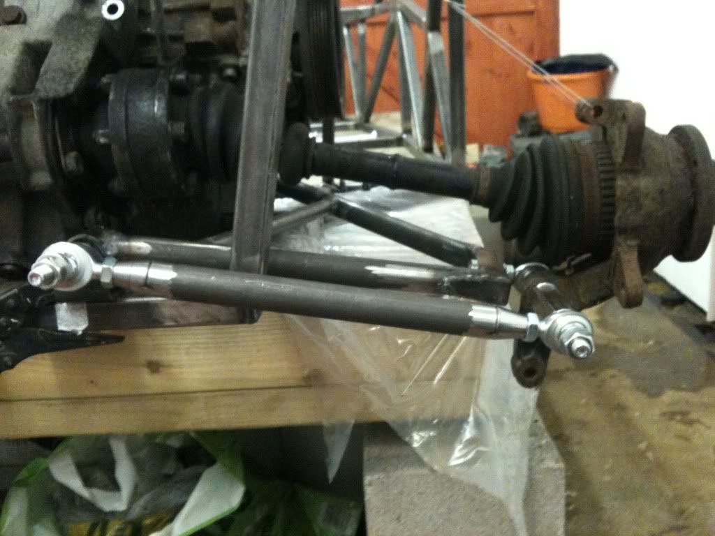
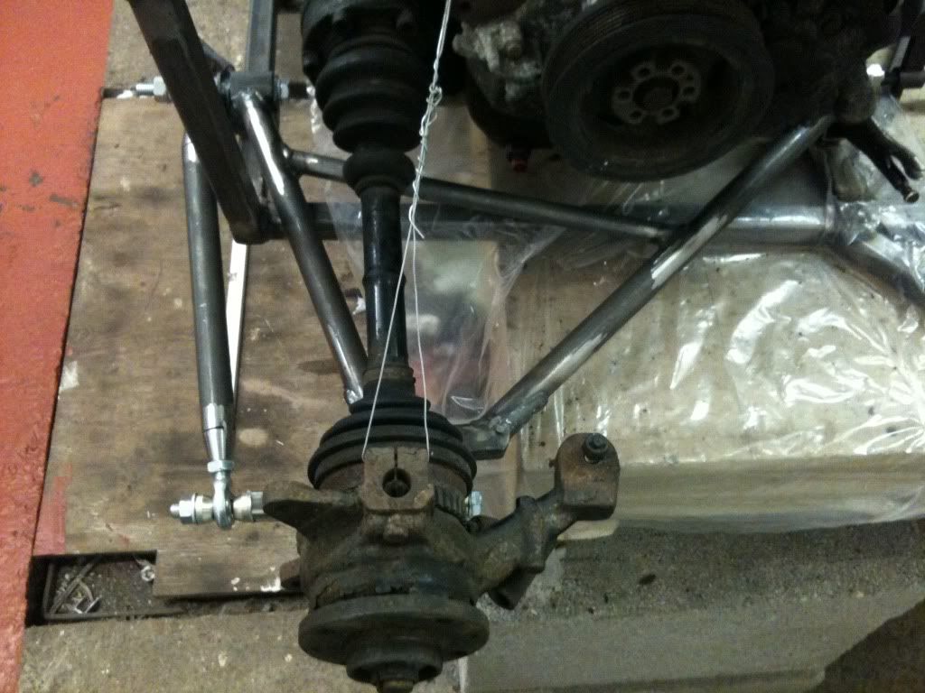
I've played around with the positioning of the A arm and think I've sorted the plung on the drive shaft so should all run smoothly.
Any advice on what initial settings I should use for Camber, Toe?
Rob
20vt powered rear engined locost
|
|
|
|
|
jimmyd
|
| posted on 15/1/13 at 09:36 PM |

|
|
Good work chum but don't be surprised if you get some stick over the orientation of the rod ends. But I guess you know that.
J
|
|
|
Slimy38
|
| posted on 15/1/13 at 10:15 PM |

|
|
What's your thinking behind the square hollow section to mount the rose joint? Doesn't that leave you with a 4 sided arrangement instead
of a triangle?
I like the idea of the extra 'tongue' bits both to provide reinforcement and to close off the ends. Did you have much of a gap to fill
between the tongue and the round tube?
|
|
|
mark chandler
|
| posted on 15/1/13 at 10:16 PM |

|
|
Looks like a very well engineered solid job.
Where are you going to land the shock, infront of the of the half shaft ?
|
|
|
designer
|
| posted on 15/1/13 at 10:54 PM |

|
|
As said, I don't like the square section to mount the rose joint, it's become a square instead of a triangle.
And have you strengthened the square section where the joint is mounted?
|
|
|
unijacko67
|
| posted on 15/1/13 at 11:08 PM |

|
|
You can see the sleeve in the square section, look's good.
http://www.kittenkitcar.co.uk
|
|
|
Slimy38
|
| posted on 16/1/13 at 09:26 AM |

|
|
quote:
Originally posted by unijacko67
You can see the sleeve in the square section, look's good.
You've got better eyesight than I have, I couldn't see anything other than the rose joint fixing itself? The picture of the two SHS
sections laid on the vice shows a rose joint partially fitted and I can't see any sleeve?
Unless I don't know what I'm looking at (which is extremely likely!).
|
|
|
phelpsa
|
| posted on 16/1/13 at 10:11 AM |

|
|
quote:
Originally posted by Slimy38
quote:
Originally posted by unijacko67
You can see the sleeve in the square section, look's good.
You've got better eyesight than I have, I couldn't see anything other than the rose joint fixing itself? The picture of the two SHS
sections laid on the vice shows a rose joint partially fitted and I can't see any sleeve?
Unless I don't know what I'm looking at (which is extremely likely!).

[Edited on 16-1-13 by phelpsa]
|
|
|
Slimy38
|
| posted on 16/1/13 at 11:19 AM |

|
|
Yeah, that's the picture I'm thinking of. But I can't see a sleeve? If anything, the angle of the rose joint compared to the SHS
suggests that there is nothing inside the steel keeping it straight.
|
|
|
phelpsa
|
| posted on 16/1/13 at 11:52 AM |

|
|
The larger diameter silver bit hanging out the back of the tube is a threaded insert about an inch long and 3/4 diameter by the looks of it. That is
welded in and the rod end is screwed into it.
|
|
|
Slimy38
|
| posted on 16/1/13 at 12:48 PM |

|
|
Aha, now I understand. I'm guessing when the picture was taken it was in place but not welded (no trace of filler or heat change on the steel).
Thanks for pointing it out to me, I thought I was missing something obvious! 
|
|
|
b14wrc
|
| posted on 16/1/13 at 12:49 PM |

|
|
Hi all,
Thanks for the comments. To answer some of the questions:
1. Yes, there are inserts for the rose joints, can you not see them? They are not welded yet but fit into the back of the square section. Thanks
Phelpsa for helping with pointing this out to those who missed it, I’m glad you understood.
2. The reason for the square section was a) to help with keeping the rose joint square when the locking nut was tightened, b) the shock will be
mounted to it in front of the half shaft.
3. I liked the tongues, it seemed a good way to reinforce the butt joints. I basically tack welded them in place and hammered them down using the
round part of my hammer, there was a slight gap, but I did two runs of weld to completely fill the V between the round and flat tube. Worked well.
4. I also plan to add a piece of 50mm wide 3mm thick flat bar on the underside of the arm to reduce the flexing as it is not a triangle or I may add
another tube from the cross member to the corner where the shock will fit.
Rob
20vt powered rear engined locost
|
|
|
Slimy38
|
| posted on 16/1/13 at 02:26 PM |

|
|
quote:
Originally posted by b14wrc
1. Yes, there are inserts for the rose joints, can you not see them? They are not welded yet but fit into the back of the square section. Thanks
Phelpsa for helping with pointing this out to those who missed it, I’m glad you understood.
Yep that was entirely my bad, I had no idea what I was looking at! I just thought it was a big washer.
|
|
|
b14wrc
|
| posted on 19/1/13 at 08:52 PM |

|
|
Top arm construction:
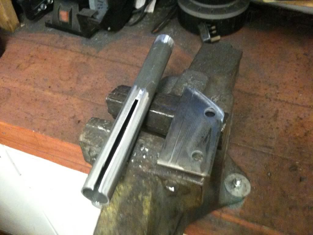
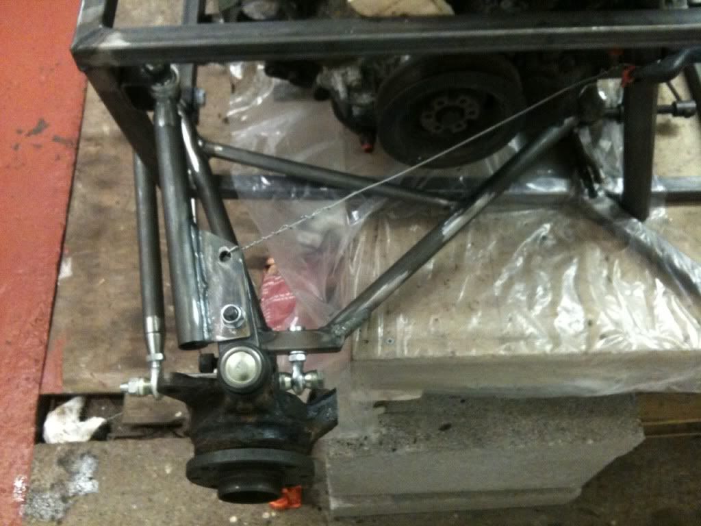
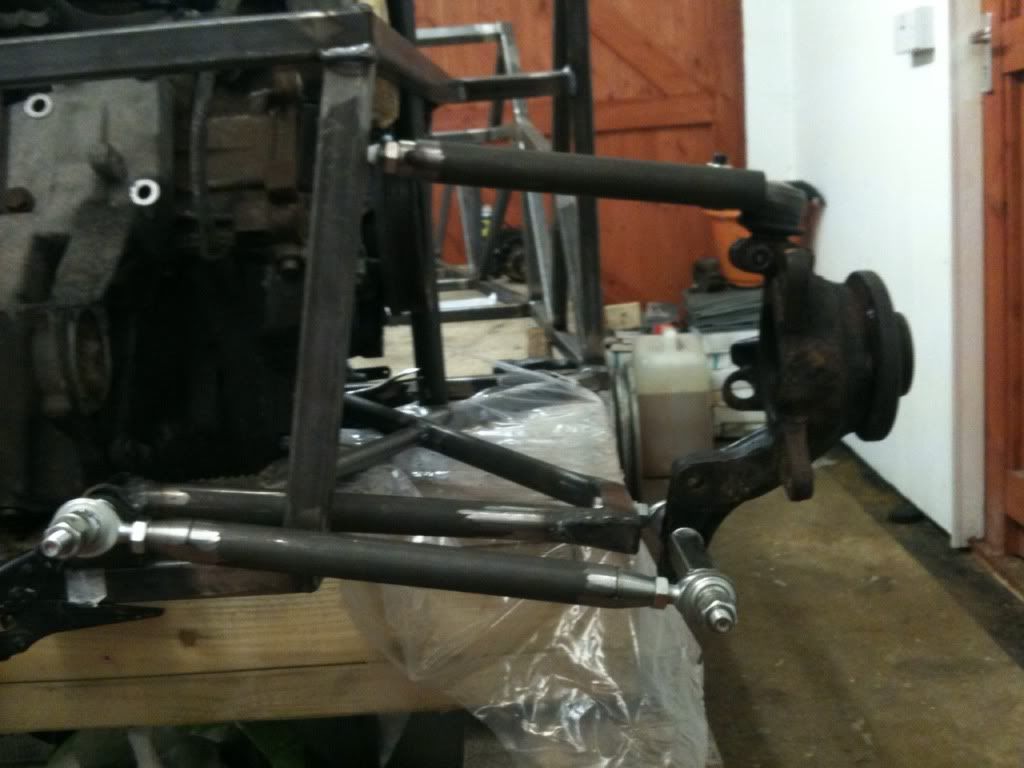
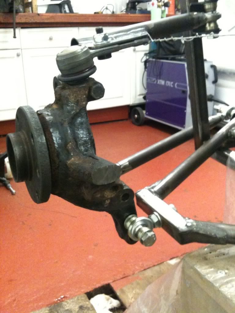
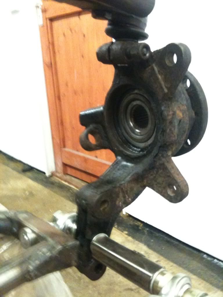
Still a bit of work to do, but when I tested the travel the camber seemed to stay fairly constant, if any thing it gained a little positive camber at
full compression. Assume this is normal?
Need a link rod to replace the wire!
Rob
20vt powered rear engined locost
|
|
|
maccmike
|
| posted on 19/1/13 at 11:28 PM |

|
|
looking great
|
|
|
b14wrc
|
| posted on 26/1/13 at 07:59 PM |

|
|
Just an update on this weekends work:
Made the second wish bone
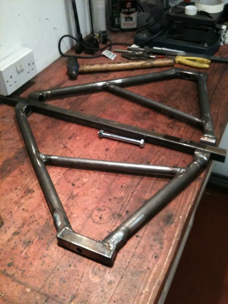
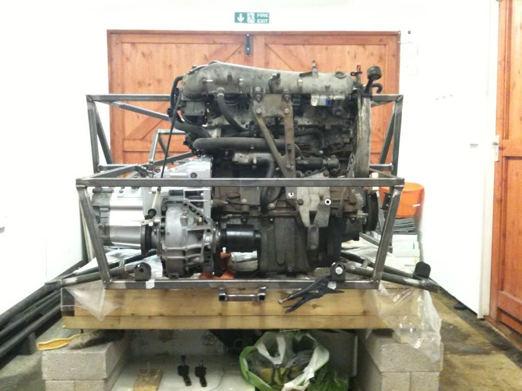
And the wire has gone;
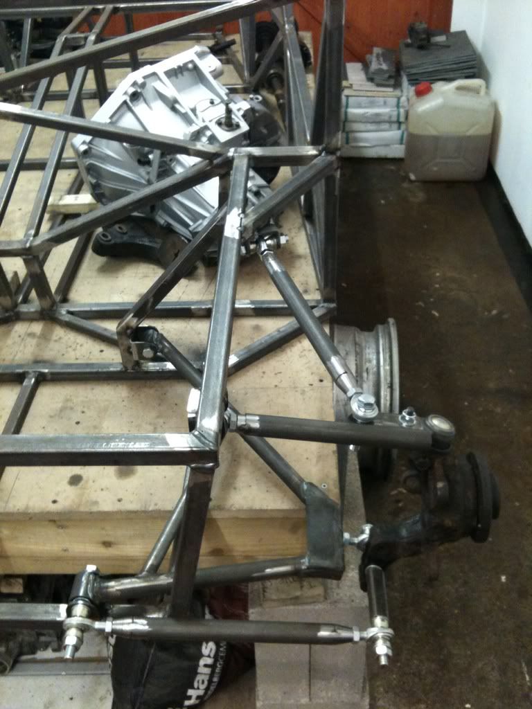
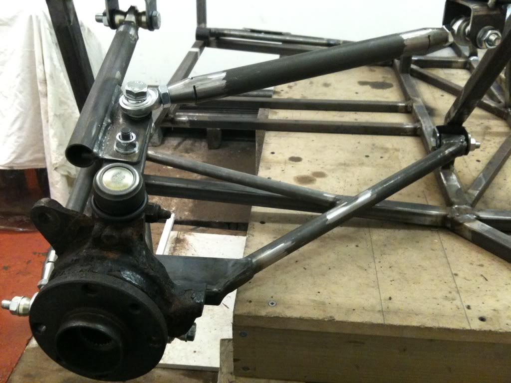
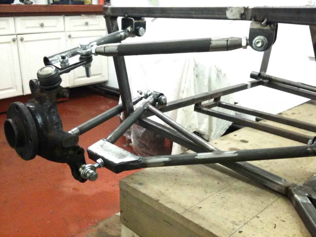
Got a few changes to make, top arm is too long, and then need to cast the PU bushes, not made the mould yet though!
These cars take a lot of work! Pretty pleased with the way it's coming to gether, hope engine fits in still.
Rob
20vt powered rear engined locost
|
|
|
TAZZMAXX
|
| posted on 26/1/13 at 09:37 PM |

|
|
quote:
Originally posted by
b14wrc
Still a bit of work to do, but when I tested the travel the camber seemed to stay fairly constant, if any thing it gained a little positive camber at
full compression. Assume this is normal?
I'm no expert on this but I do have a pile of books on suspension design that I'm ploughing through at the moment. I would have thought
that positive camber would be undesirable as, when coupled with body roll, it will increase and reduce tyre contact patch. The angle downwards on your
top arm looks to exceed the angle on the lower arm which is what is creating your positive camber increase. If it were level (top arm) with the lower
arm angled down will will go to slight negative whereas angling the top arm upwards (lowering the mounting points) will increase your negative camber
which would be more desirable. It's a really interesting subject that you really need to get to grips with if you want your car to handle
well.
Good on you for what you've done so far, it looks good and there's always more than one way of doing things. Don't take the above as
criticism but I think you could do some simple alterations to make it loads better.
Cheers.
[Edited on 26/1/13 by TAZZMAXX]
|
|
|
MikeRJ
|
| posted on 26/1/13 at 10:44 PM |

|
|
The entire corner weight is being supported by a single rod end in a bending moment. I hope you have done your sums!
|
|
|
Grimsdale
|
| posted on 27/1/13 at 09:57 AM |

|
|
why not mount the top arm to the outer bolt on the ball joint? then you are reducing the bending moment on the top wishbone. It does not look right as
it is.
|
|
|
Doug68
|
| posted on 27/1/13 at 10:07 AM |

|
|
quote:
Originally posted by MikeRJ
The entire corner weight is being supported by a single rod end in a bending moment. I hope you have done your sums!
What he said, where is the shock going to attach? To the top arm, bottom or the upright directly?
Also it looks as if directional control of the rear wheel is dependent on the square tube coming away from the bottom of the upright being held tight
up against the upright. I think the leverage at this point would huge say when you hit a pot hole or something. It looks like you cut of the
steering arms from the uprights? I think it would have been better to have used those and dialed out the bump steer than the method shown. This is
how I did mine.
Positive camber is also to be avoided, you want negative when you start and more negative at full bump.
I hope the the above is take in a positive way, I've been through all this myself so I know how much effort it is.
Doug. 1TG
Sports Car Builders WA
|
|
|
b14wrc
|
| posted on 27/1/13 at 12:35 PM |

|
|
Morning all,
I made a mistake when I quoted positive Camber, I had mixed up pos and neg. it actually gains slight negative. I understand contact patch and roll,
that's why I was asking, I think I know the theory, just wanted other people's opinions.
Ok, a few comments, good, I was after some help. First thing though, I think your all looking at the wrong photos, the one that's quoted is not
the latest. I added new ones yesterday, please note the upper arm position has moved.
The square tube is only temporary.  I am going to make a proper bracket that will bolt to the original macpherson strut holes. 20mm tube with a
stainless crush tube inside. I am going to make a proper bracket that will bolt to the original macpherson strut holes. 20mm tube with a
stainless crush tube inside.
The single rod end corner weight? How is this, I might have missed something there? I have a pair of rod ends on the outer lower arm, the load will be
distributed through them both wont they?? Each are rated to 4 tons, so the load to failure would be 8ton pressure if all the car was hanging on the
one wheel at 3g.
Shock will be mounted to the steel plate at the end of the A arm.
I have also read many books, but it's a lot easier to build an ideal system when you don't have the engine to work around, think I have a
fairly good solution considering.
Yes, I cut the steering arms off. I didn't want to use them and thought the mojo uses this principle so - so would I.
Regards, Rob
20vt powered rear engined locost
|
|
|
Doug68
|
| posted on 28/1/13 at 12:29 PM |

|
|
Hi b14wrc,
I assume that the shock will mount to the lower A arm then?
The rod at the rear of the A arm basically cannot be taking any of the bump load if there is not something for it to react against such as a spring.
This means all the bump load has to be transmitted through the rod end into the A arm for the spring to work against.
The load values quoted for a rod end are acting axially down the shaft i.e. in your case trying to pull it out of or push it into the A arm. The load
that going into the road end though is trying to bend the end of the rod end off of the shaft.
You might want to read: http://www.aurorabearing.com/pdf/rod-ends.pdf
If you google "rod end in bending" you'll get a good few results to mull over and there's been one or two heated debates on
this forum on the subject in the past.
On the rear wheel toe control method if you've got a working example to follow, then I'll shut up on that one 
Doug. 1TG
Sports Car Builders WA
|
|
|
b14wrc
|
| posted on 29/1/13 at 12:28 PM |

|
|
Hi Doug 86,
Yes, the shock is mounting to the steel plates that are welded to the top side of the A - Arm and bolt to the top rail in the engine compartment.
I see what you are all saying about the rod end, I am thinking of replacing it with a piece of tube and having a bush there instead.
Yes, my suspension is based on the idea the Sylva Mojo uses. It actually works quite well.
Rob
20vt powered rear engined locost
|
|
|
Fred W B
|
| posted on 29/1/13 at 03:21 PM |

|
|
You can remove the concerns with the rod end in bending if you attach the coilover to the upright.
Cheers
Fred W B
You can do it quickly. You can do it cheap. You can do it right. – Pick any two.
|
|
|
daviep
|
| posted on 29/1/13 at 03:55 PM |

|
|
quote:
Originally posted by Fred W B
You can remove the concerns with the rod end in bending if you attach the coilover to the upright.
Cheers
Fred W B
I think the driveshaft will probably be in the way?
Cheers
Davie
“A truly great library contains something in it to offend everyone.”
|
|
|


