ETA found some pics of an old lotus (elan possibly) chassis and that appears to not have the track control arms. If this is the case then I may be worrying about nothing.

[Edited on 27/6/11 by renrut]

Wasn't sure where to put this as its entirely suspension and not really Middy but its definitely not typical locost either and thought I'd
get a better response here. Mods feel free to move as you see fit.
Anyway the question is for suspension gurus.
I've got a serious lack of space in the back of my little middy and having already built one suspension setup (mac strut) but I don't have
sufficient space and clearance for the track control rods. So I'm considering doing away with the lower ball joint and making new uprights and
lower wishbones so that the lower connection between upright and wishbone can only rotate in one plane for bump and droop. I would keep the upper
strut in place and not be fitting an upper wishbone but that seems to work fine for normal macpherson strut systems.
This all seems to make sense to me and should be lighter than the current setup albeit with less adjustability. But I'm starting to get worried
that I can't find an example of where this system has been used anywhere else. Is there some fundamental problem with it that I can't see?
quote:
Originally posted by renrut
So I'm considering doing away with the lower ball joint and making new uprights and lower wishbones so that the lower connection between upright and wishbone can only rotate in one plane for bump and droop. I would keep the upper strut in place and not be fitting an upper wishbone but that seems to work fine for normal macpherson strut systems.
this is a case of.... a picture speaks a thousand words.
That's what I initially thought but on looking most chapman struts appear to still have a track control rod. Or are they just misnamed macpherson
struts?
ETA found some pics of an old lotus (elan possibly) chassis and that appears to not have the track control arms. If this is the case then I may be
worrying about nothing. 
[Edited on 27/6/11 by renrut]
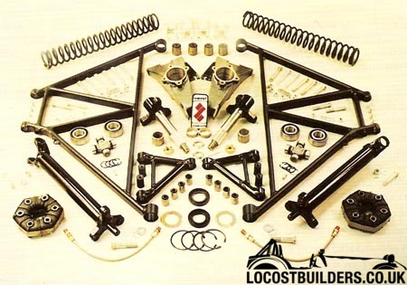
Looking at pics of some replacement suspension parts for Lotus Elan/Europa, I note that the lower wishbone has a markedly wider spread of the
attachment points. This could allow you to avoid track control arms. Maybe.
[Edited on 27/6/11 by Dick Axtell]
quote:
Originally posted by ashg
this is a case of.... a picture speaks a thousand words.
quote:
Originally posted by Dick Axtell
Looking at pics of some replacement suspension parts for Lotus Elan/Europa, I note that the lower wishbone has a markedly wider spread of the attachment points. This could allow you to avoid track control arms. Maybe.
I think what you are proposing is to replace the lower balljoint with a simple bushed pivot? If so this this method is widely used on Locost IRS
designs. By using a rectangular "wishbone" (suitably triangulated!) you can attach the bottom of the upright via two rod ends to give you
some toe adjustment.
This scheme doesn't allow you to add/remove toe-in on bump as a separate track control arm would, but some may regard this as an advantage, since
getting this correct can be tricky and getting it wrong will make a very ill handling car.
[Edited on 27/6/11 by MikeRJ]
I had a look over a lot of locost IRS designs but they all still seem to have a top wishbone which this wouldn't but yes thats pretty much it.
It's amazing how many ways other people can say the same thing simpler than myself!
I don't foresee any major issues translating this to a simple McPherson strut design. I'm certain this scheme has been used on some
production cars though I don't know which ones off hand.
I guess this shows the basic design (though probably not with drums and universal jointed driveshafts):


is the gearbox in the way of a de dion setup ?
lotuses have non plunging driveshafts as part of wheel control .
quote:
Originally posted by Volvorsport
is the gearbox in the way of a de dion setup ?
lotuses have non plunging driveshafts as part of wheel control .
quote:
Originally posted by Volvorsport
is the gearbox in the way of a de dion setup ?
lotuses have non plunging driveshafts as part of wheel control .
quote:
Originally posted by renrut
I do have plunging driveshafts. Is that likely to make a big difference as surely it will need some sort of wheel to diff movement with the axle swing?
I don't know of any 1/2 shafts that don't plunge in some way unless they're being used as part of the swing axle for example.
Most I believe achieve it by plunge in the CV joint itself.
Back to your original question, it sounds to me like you've designed yourself into a corner. Either:
a. You compromise and do what you've describe above.
b. Layout the suspension you really want and rework the rest of the design until it fits.
It may seem like a lot of work to do now, but in a few years when you are driving the thing and its too late to change will it bother you or not?
Well mine plunge as part of the inner CV joint so thats that.
I'm well aware I've designed myself into a corner, mostly through making too many assumptions at the starting point (I'd have used a
shorter engine for a start!) and trying to retain too much of the original car to save effort which has backfired. Laying out the suspension I should
really use (double wishbone) is basically rip it all up and start again type of problem as the whole rear chassis will need remaking.
Having internet investigated the 60s Elan and Elan+2 which is the only example of this suspension style being used on a production car it works well
but it doesn't handle high suspension loads very well (e.g. powerful engines and sticky track tyres) and tends to lose its rigidity as a result.
Lotus stopped using it after the Elan and went to double wishbone and there are a lot of kits out there to convert Elans to double wishbone which
suggests it was an experiment that didn't quite work.
Having said that I don't intend to put sticky track rubber on (its a weekend toy and occasional track car rather than dedicated) and the Elan
suspension was some of the best in the day anyway so its hardly like I'm moving over to cart springs and wooden wheels.
I think this is the way to go. If it doesn't work I'll still need to rebuild the whole back of the car anyway. If it works then I've
got a nice simple lightweight suspension setup.
If I make the lower joint between upright and wishbone out of rose joints rather than using a bush setup this would hopefully improve its location as
well. I'll still have the bushes at the wishbone to chassis joint so should still maintain some compliance.
Now I'm going down this route I'm looking for some advice and experience from the knowledgeable chaps on here.
It looks like I'm going to have to fabricate my own uprights unless I can weld to the existing ones. I believe the existing ones are steel so
should be doable but is there a big IVA/MOT no no about doing so or is it ok as long as the welds are good? This would obviously save me a lot of
hassle as the only bit I really want to change is the lower wishbone link.
Secondly what sort of size rose joints should I be looking for to attach the lower wishbone to the upright? It'll be 2 so I can nicely adjust the
static toe to how I want it. I figure I need something at least as strong as the existing lower ball which is attached to the upright by a typical
taper into the upright which ends with a M10 thread so probably average about 12mm diameter.
Would 2x M12 rose joints (one either side of the upright) be sufficient or should I be looking for something beefier like M14? I'm struggling to
find proper strength information on rose joints.
What uprights are you contemplating welding to?
If they are Ford, they may well be cast SG iron. Non weldable.
Check them with a file first.
Cheers,
Nev.
quote:
Originally posted by Neville Jones
What uprights are you contemplating welding to?
If they are Ford, they may well be cast SG iron. Non weldable.
Check them with a file first.
Cheers,
Nev.
Done some test welds on a spare upright. Looks to have taken, repeated bashing with a large hammer doesn't seem to have done anything other than
round the edges a little.
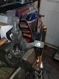
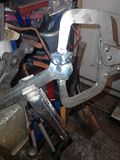
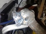
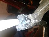
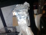
Yes I know they're not pretty, its to test if it works or not. Any wise thoughts?
Next I guess would be making up the brackets to go on the bottom.