CAD drawings of Midtec chassis
Bart-Jan - 2/1/06 at 11:58 PM
I've read several topics about 'universal' mid-engine designs. I also was looking for one, last year and found a complete chassis of a
Midtec Spyder. It is designed by Lee Noble (also designed the Ultima...) and is known to have very good characteristics. It uses a traditional style
front suspension with Cortina uprights. But because the engine is situated longitudinal, at the rear also a traditional suspension is used with
wishbones just like 7 style cars. I'm currently in the process of drawing it in CAD. The chassis itself is ready; the wishbones not yet. I will
post some drawings tomorow.
I also thought about the difficulty with the body, until I found out that the dimensions for the Midtec are alomst identical to a Lotus Elise. The
only difference is the length of the engine room. And second hand (damaged) Elise clamshells can be bought very cheap on Ebay in the UK. Sounds easy;
I will find out whether that's true...
The thing I'm interested in, is to have some CAD files of humans to place in the car. Can I download them somewhere from the internet? I've
seen many of you guys use them (Jcduroc for instance has used them).
stevebubs - 3/1/06 at 01:56 AM
Stuart Taylor bought the rights to the midtec...not seen them in production recently but they may be able to point you in the right direction to get
an original body made up... but it's love it or hate it styling (I quite like it)
rusty nuts - 3/1/06 at 10:41 AM
I like the Midtec myself , read or heard somewhere that Lotus used one when designing/developing the Elise but not sure if that is true .
Bart-Jan - 3/1/06 at 04:23 PM
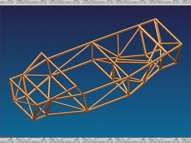
I promissed to post a drawing of the chassis of the Midtec. Here it is.
I know Stuart Taylor bought the project, but I also read somewhere that he already had sold it on... He did change the odd looking Frogeye-like
lights, which is a good thing. But especially the back end, I don't like. I'm not sad for not having the body...
My question remains: can somebody help me in the direction to find some 3D CAD files of dummy humans (how are they actaully called?)


Rescued attachment Old-chassis-complete-R1.jpg
bikkel - 3/1/06 at 05:13 PM
bartjan
look here
on the bottom of this page:
link
grtz
koen
NKCC - 1/2/06 at 08:02 AM
Hi,
is the chassis drawings produced in "Autodesk Inventor" ?
thanks
iank - 1/2/06 at 09:12 AM
Professional models to really check out ergonomics are expensive.
You can get demo versions of some packages though e.g.
http://www.lboro.ac.uk/departments/cd/docs_dandt/research/ergonomics/sammie/samdesc.htm
Looks like Ariel used it for the atom:

As a semi thread-hijack has anyone seen any 2D CAD models of people (side view) pref .dxf?
Bart-Jan - 1/2/06 at 12:09 PM
The chassis drawing is made in Unigraphics, which I use for my work. My daily job is the development of consumer products, e.g. the Senseo and shavers
(both Philips). Philips also uses UG, just like mainstream car manufacturers.
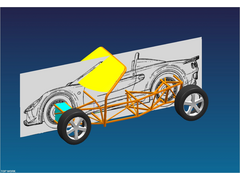
I added a drawing of several parts added to the chassis and a background of a Lotus Elise. I intend to use the clamshells of an Elise
Bart-Jan - 1/2/06 at 12:16 PM
Lol... I tried to add a picture. I didn't succeed. Another try...


Rescued attachment Main-assy.jpg
NKCC - 1/2/06 at 12:53 PM
All very Interesting, we are an Autodesk Software Developer.
Its slightly different to my chassis, but then to be expected.
[Edited on 1/2/06 by NKCC]
cymtriks - 4/2/06 at 11:58 AM
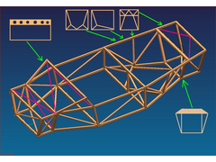
Mods as shown.
Front suspension top diagonal
Footwell end diagonal
Footwell top diagonal
Welded in dashboard
Three alternatives for the engine bay
A diagonal over the rear suspension
A tude and panel arch over the transaxle


Rescued attachment midtechmod.JPG
Bart-Jan - 4/2/06 at 02:40 PM
thanks Cymtriks for your suggestions.
Funilly, the strengthening suggestions you made about the engine area and rear suspension area are already integrated in the chassis. It seemed my
first drawing wasn't complete. You can see how Lee Noble designed it in my second drawing (the one with the Elise integrated).
As for the front section, Originally the footwell was between the wishbones. Now, with The Elise clamshells, I need to lengthen teh chassis, otherwise
my nose will be against the windscreen. I can than place the fuel tank between the front wheels (blue part in the second drawing).
More importantly, have you got suggestions of what construction to use for lengthening and widening the passenger area?
cymtriks - 4/2/06 at 08:40 PM
If you look closely I've taken out the original top tubes from the engine bay and rear suspension.
My suggestions for the engine bay are better, for stiffness, than the original layout but you will need to watch engine and anciliaries clearance with
the different tubes. That's why I've made three suggestions, there's a good chance that one of them won't fit your engine!
Having your feet too far forwards between the front wheels is bad for safety, you are right to move them back a bit.
You could angle the rear of the passenger area to match a sloping seat back. Make the vertical tubes higher,so that they go above the rest of the
chassis tubes, and put in a higher cross piece and you have somewhere to mount the seat belt.
Personally I'd put in a welded 18 guage steel floor. Riveted aluminium floors can work loose!
Fred W B - 5/2/06 at 12:44 PM
Some ideas and discussion here
Cheers
Fred W B


df canamsa proto side pod
[Edited on 5/2/06 by Fred W B]


