drt
|
| posted on 4/12/17 at 01:30 PM |

|
|
I'd love to put it on the road, but it seems mine is the worst country in the world for such a thing.
So euhm I have a little route around the leg.
Thanks I always loved the roverK, it should bring me to -500kg now... that will allow me to trailer it (750kg)
|
|
|
|
|
drt
|
| posted on 14/1/18 at 10:24 PM |

|
|
So
Finally started on extracting the K-series...
And doing other stuff in the lid workshop during the long evenings.
For the sake of honesty ... when I designed the car I never had never seen the uprights but had parametric kinematic designs for the placements of
pick up points... in my stupidity I guesstimated the location of the steering arm.
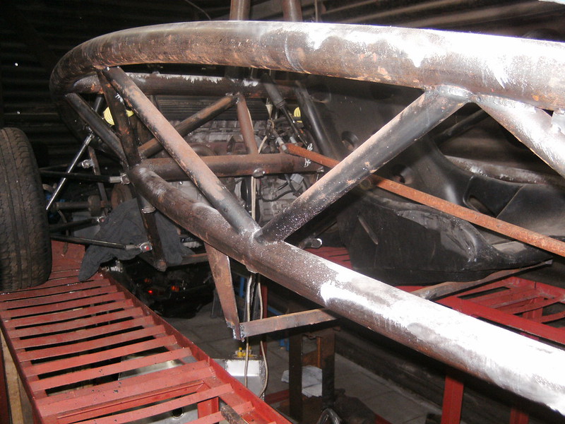
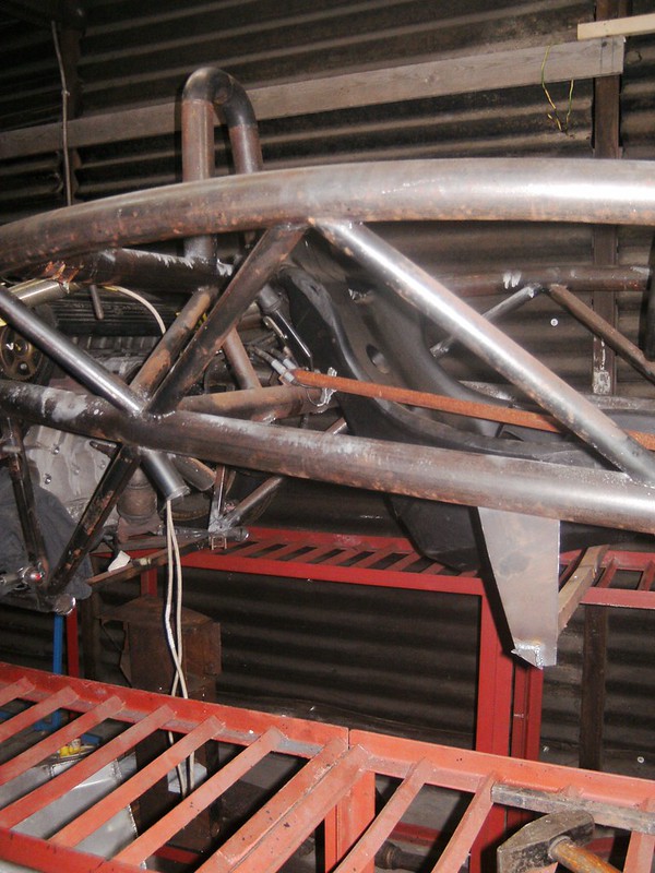
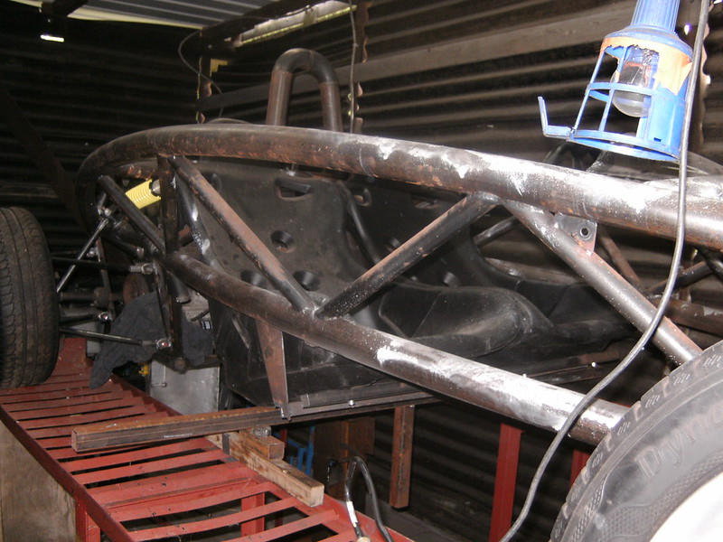
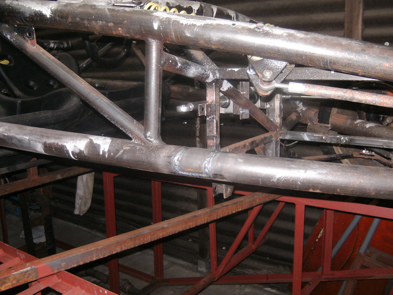
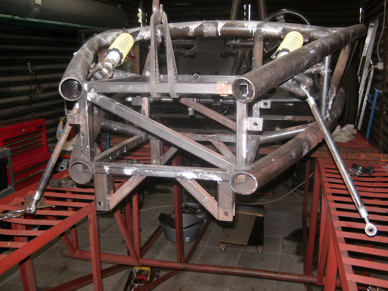
And that bit me in the ass as later appeared that the only bumpsteerless route was through the chassis member 
FFS
[img]
[img]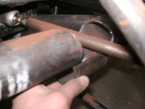
Because of the top A arm interfering I can only reinforce the bottom and cross brace above... a bodge... But I can see no other way
|
|
|
drt
|
| posted on 14/1/18 at 11:33 PM |

|
|
Why so little progress ?
In 2017 me and my daily where taken of the road by a hit and run.
With no funds I set out to get a cheap daily, had to restore one in the end.
Finished I was faced by sudden a 10 fold road tax increase and was priced out.
Sold it at the original price despite the resto because the market had caught on to the tax regime.
With only commercial vehicles exempt from the tax man (yeey capitalism) I had to try for a van...
A T4 was the only thing reliable and in budget... well in this state
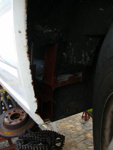
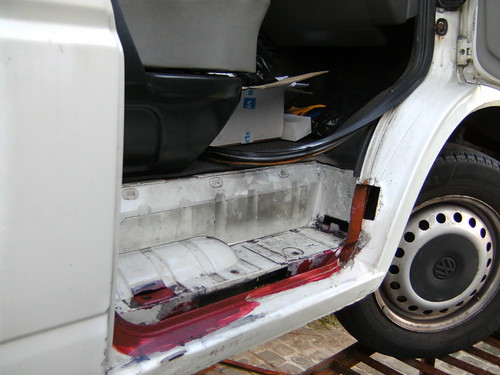
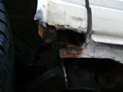
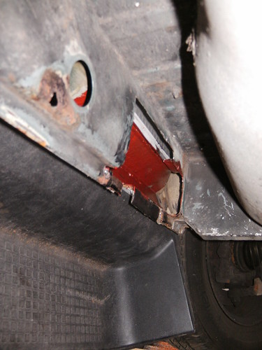
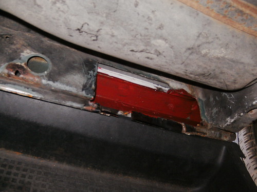
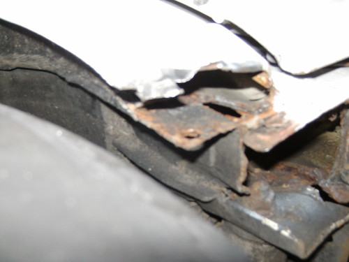
So on top of that new brakes, turbo, suspension, bumper beam, back garden respray, fuel pump and other weld work ... we're mobile once again.
2017, I won't miss thee
|
|
|
drt
|
| posted on 22/2/18 at 09:10 PM |

|
|
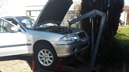
Engine out today
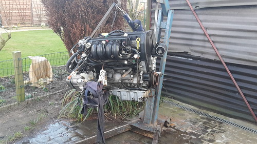
After cleaning
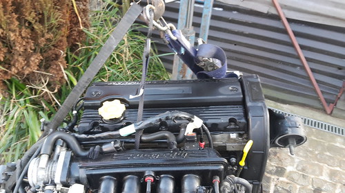
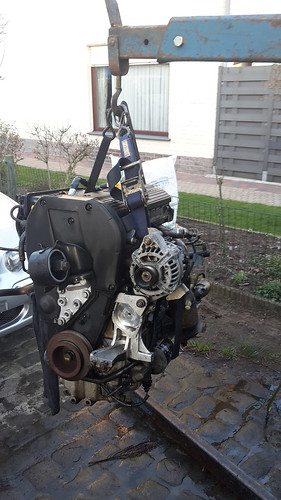
threw away the ancillary's... now how to route that alternator ?
|
|
|
drt
|
| posted on 15/3/18 at 10:15 AM |

|
|
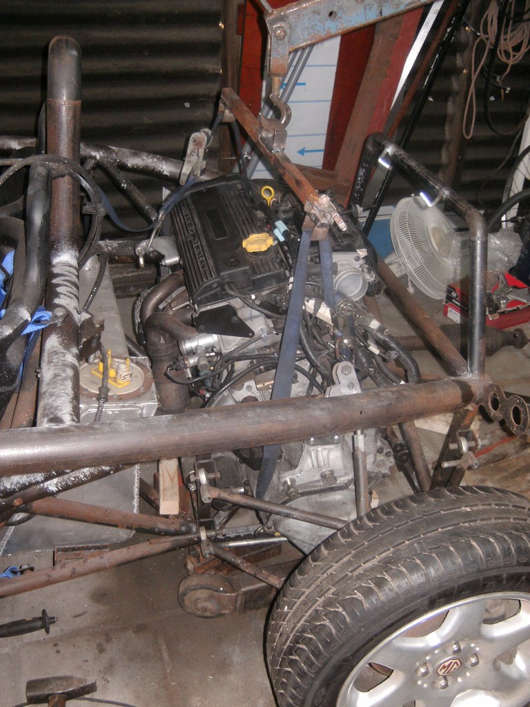
So, the alternator bracket thing for a non-AC set up arrived.
In the process of fitting the engine...
I was a bit gobsmacked that the roverK is bigger than the saab B204/205 !!
The belt drive camshafts are a cause I presume, but in all rover choose toe make the engine wide and low, while the saab's was fat, high and
narrower
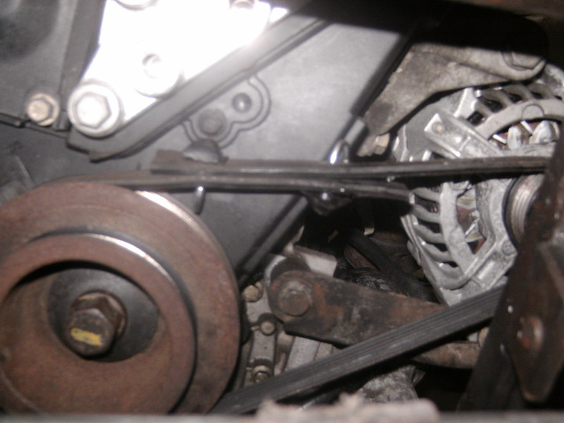
I don't get why people buy new belts, works fine
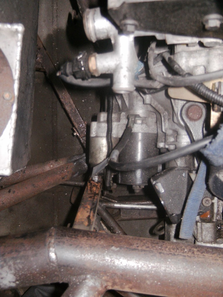
Starter position is not helping me
|
|
|
drt
|
| posted on 12/4/18 at 10:42 PM |

|
|
soo putting in the RoverK in...
I was getting worked up about having to weld driveshafts again so decided to tackle the suspension issue first.
because -those who followed- there is a large chasm in the front chassis member to let the steering arm go through.
The only solution is to give the suspension a parallel geometry, since then I can move the rack around without causing bump steer.
So I was gonna go for that... screw the camber comp...
Since that meant I might had to redo the wishbones I was thinking to narrow the track (1600mm now) to accommodate the
OEM rover 45 (track=1475mm) wishbones
(saving me that heart ache as well)
BUT i stumbled upon the most wonderfull thing!!!!!!!!!!!!
While trying to fit the driveshafts it became clear the rover 45 CV's wouldn't fit the MGF hubs.
Crying out loud I -while swearing- fitted the MGF CV's on the Rover shafts... and lo and behold...this combo apparently takes the track to
1590mm
So problem solved since there is enough adjustment in the current wishbones and in the gearbox side CV.
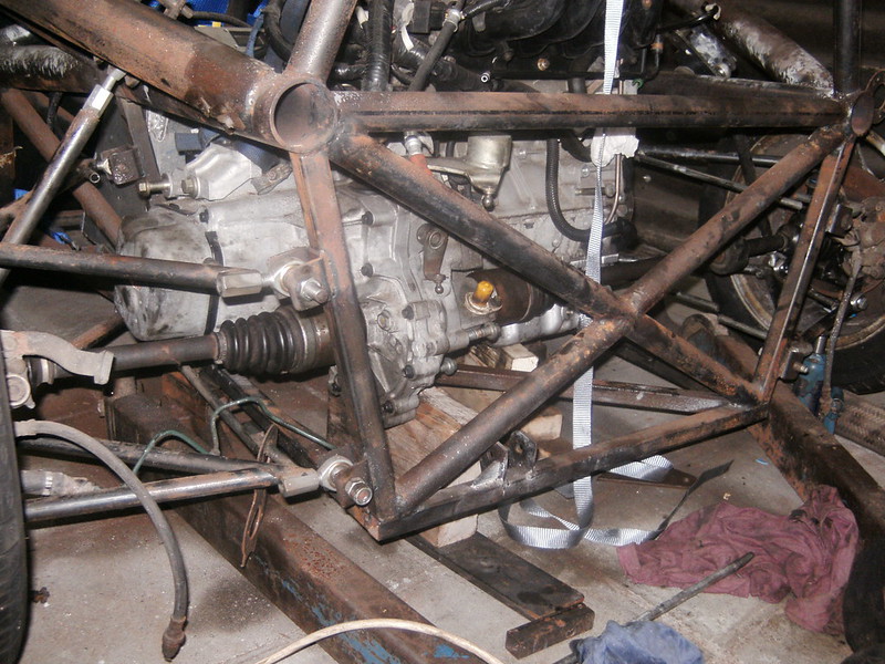
So now making new suspension pick-up points
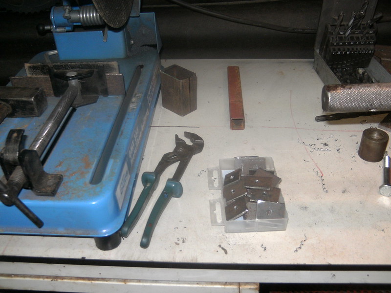
|
|
|
drt
|
| posted on 16/5/18 at 03:45 PM |

|
|
Ok so nobody impressed by the wideness of the rover MG combi driveshafts...
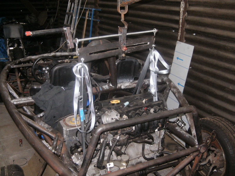
Been trying to fit the engine for weeks... but keep struggling to find the best compromise.
The more you know the less you know, it's a curse
Bodged a load spreader bar the easily level the engine.
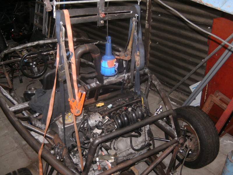
Still added 4 ratchet straps to change the inclination on the go.
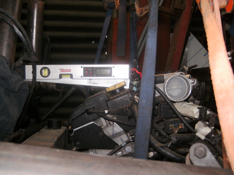
But now not sure about how the engine will take the angle
|
|
|
drt
|
| posted on 19/5/18 at 12:02 AM |

|
|
So I went with the 11.1 degrees in the end...
Finally started fitting...
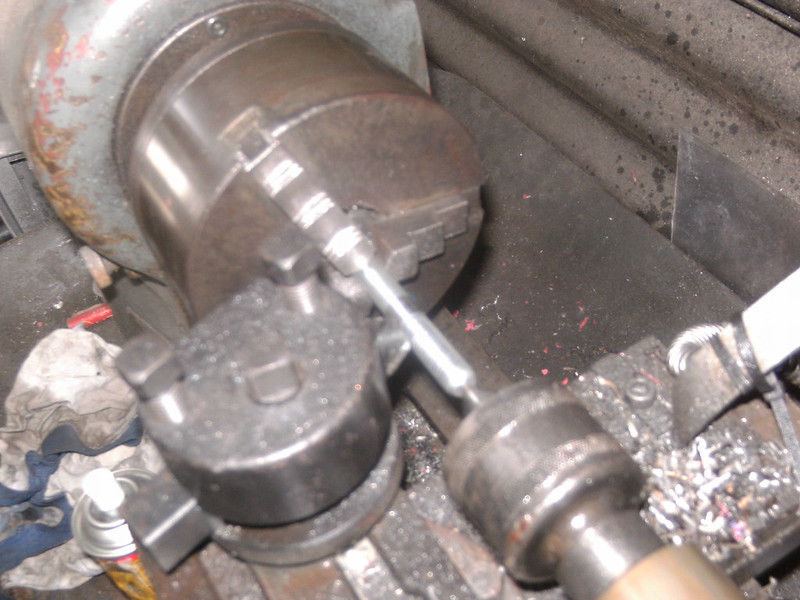
Machining a stud with M12 thread on one side and M10 smooth+threaded on the other
Why?
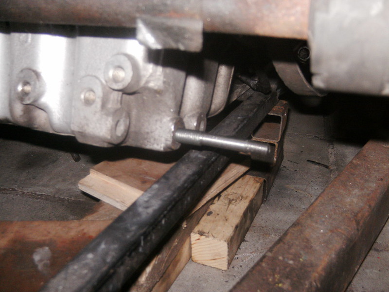
So it will fit the engine and the take the bushings I have
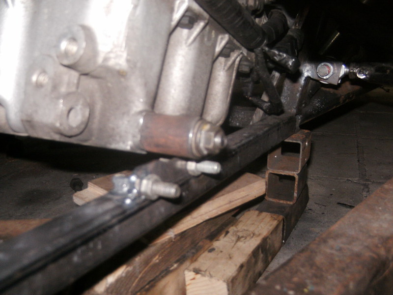
After much consideration decided to fit the bracket this way as it was easiest to (re)fit an engine this way
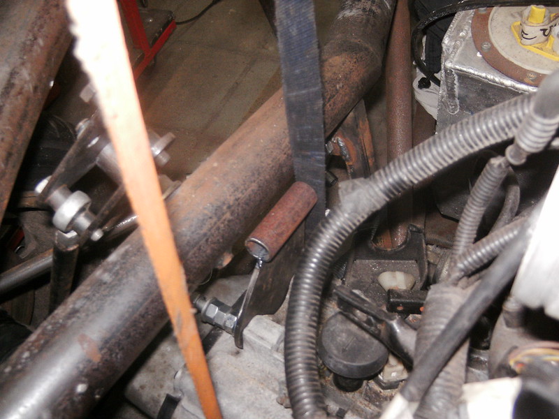
Gearbox side
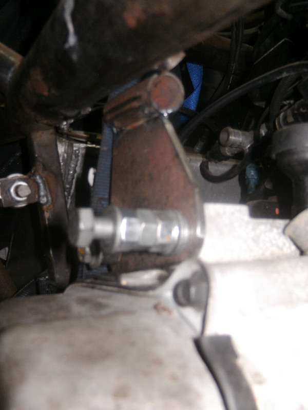
Going ...nuts... doing these bolts up 20 times an hour
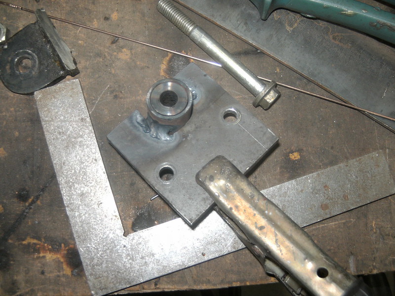
Lower mount tagged on in situ and now being welded fully.
A machined steel bushing temporary takes up the space of the rubber one... makes fabricating much easier and beats burning rubber
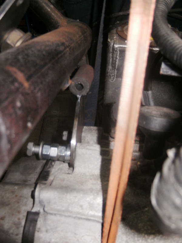
Gearbox side fully welded and rubberised
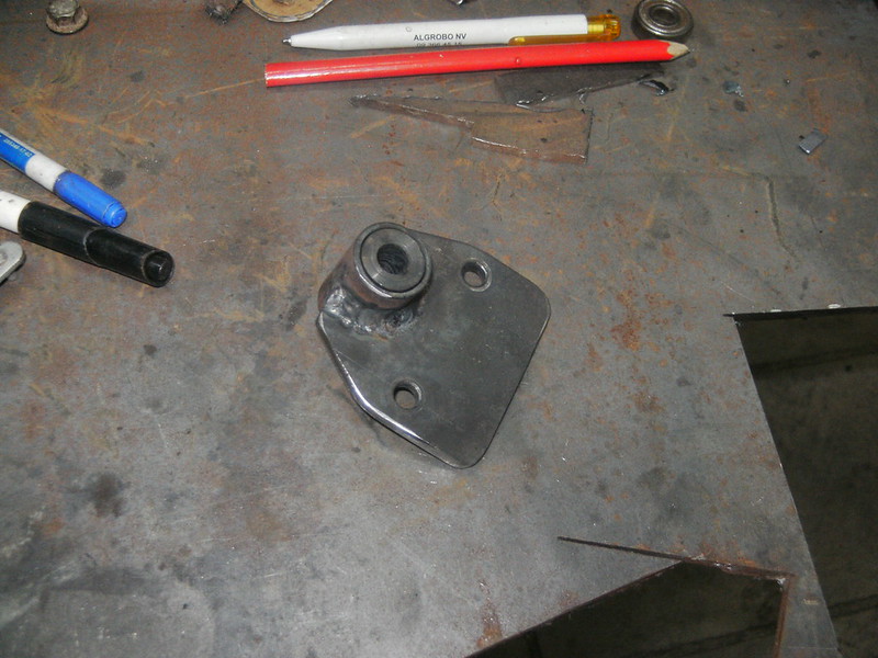
Lower side finished
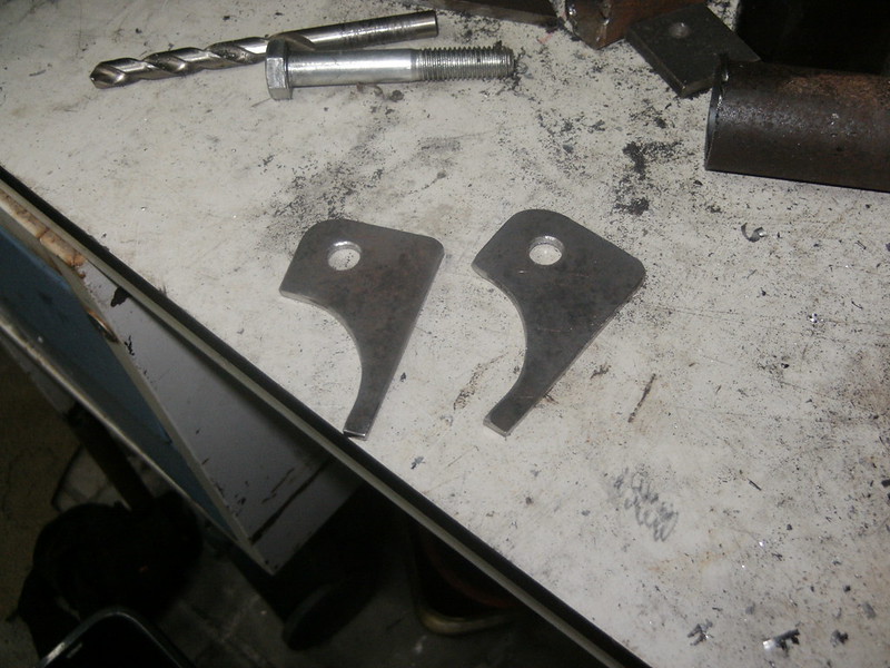
Gearbox side brackets... who needs a laser cutter anyway
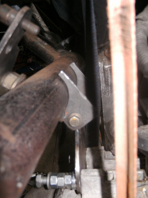
Like zoo
Started on the third and fourth engine mount... more on that tomorrow
|
|
|
drt
|
| posted on 23/5/18 at 12:00 AM |

|
|
A little word on the engine mounts...
I see a lot of people use the PU tophat type suspension units, and those are waaaay to stiff to filter any vibration.
Even so if you do the arithmetic, given the frequencies of an engine and a stiff light frame, it is very hard to isolate the one from the other.
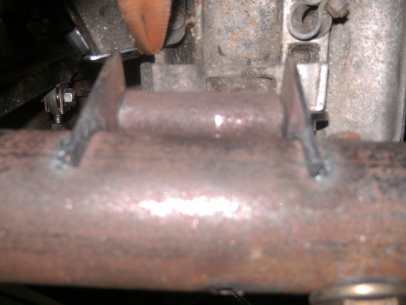
Must make sure the sprung doesn't touch the unsprung
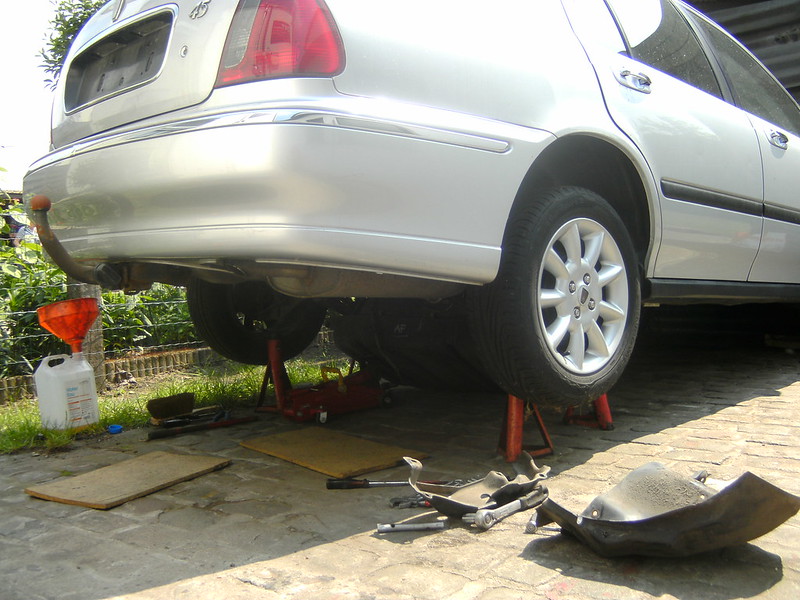
I wanted the Rover fuel pump as to keep things together, for a multitude of reasons.
Ofc you can't get to the tank from the interior... Grrrrr... out with it than
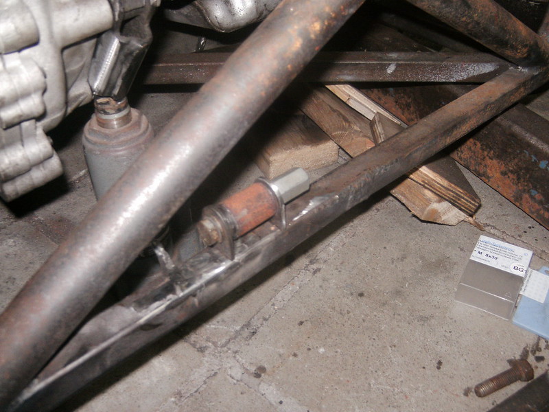
The last mount
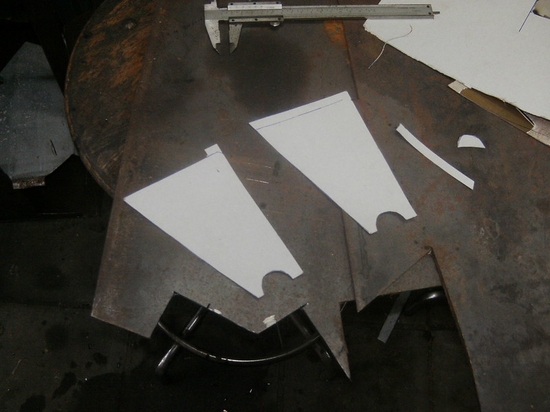
Some CAD
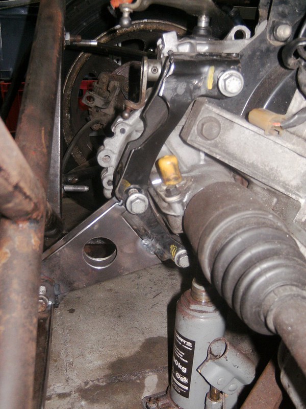
Mocked up
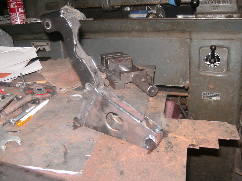
Welded
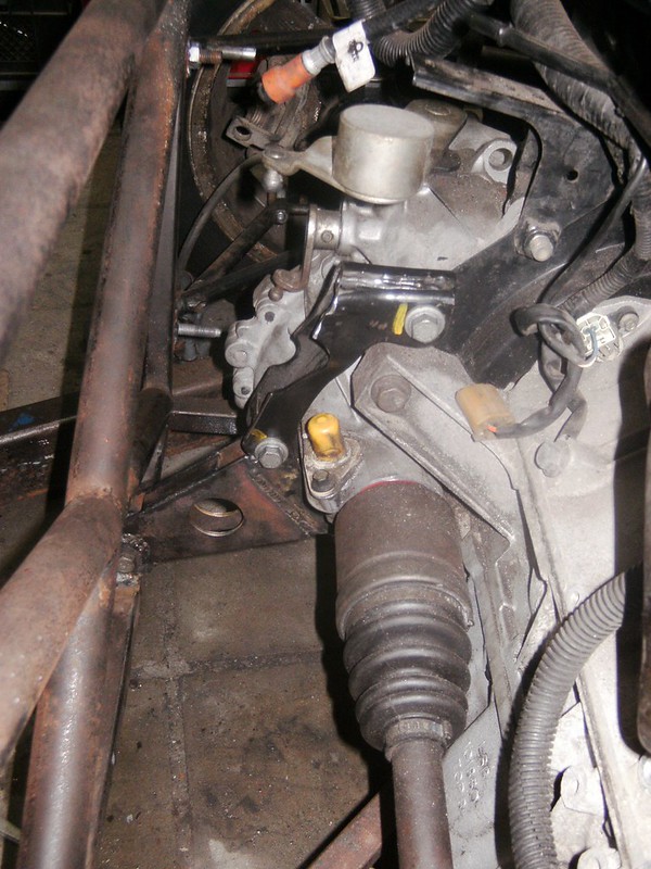
Done...
Now she's going on the ramp again so I can clean up and clear the cave
|
|
|
drt
|
| posted on 25/5/18 at 06:22 PM |

|
|
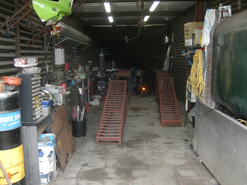
As you can see the cave needed some attention... made use of the car being out to set up the ramps
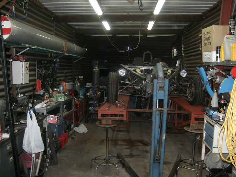
She is on the ramps again... far better to work standing up
Still a mess, although the floor is hoovered.
I'll get you guys an after picture as well.
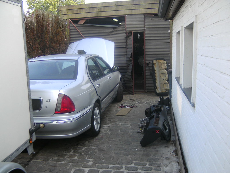
Since it was such a nice day today I thought to strip the harnas from the Rover.. as in not to be cooped up.
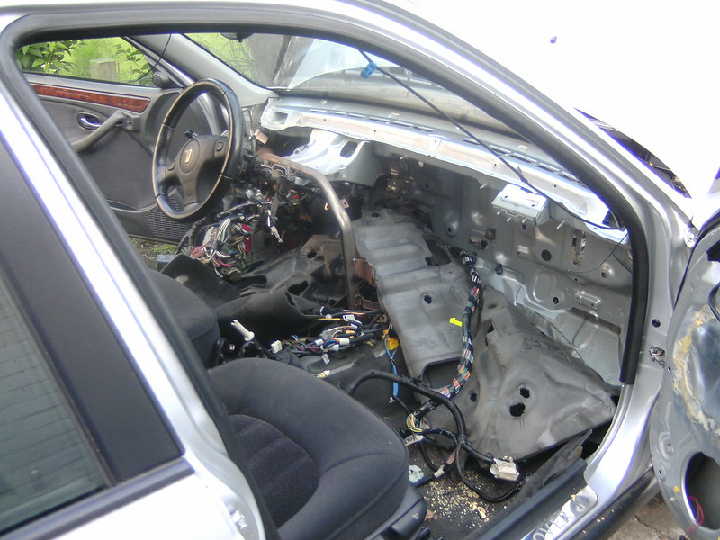
My mistake... what an absolute pain in the ...
Thanks rover for hiding it behind EVERYTHING... trim, heater, pedalbox, you name it, it's out.
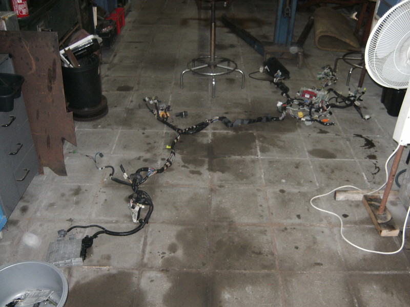
So just a quick bite, upload photo's and on with the jungle of wires...
As I see it, and please correct me, the MEMS just needs the key-fob-detector-thing and power going to it from the interior side of things?
The engine side is a separate connector... so not involved in this discussion.
|
|
|
drt
|
| posted on 12/6/18 at 11:53 PM |

|
|
Sooo after going through wires upon wires like a hairdresser trying to separate the interesting ones...
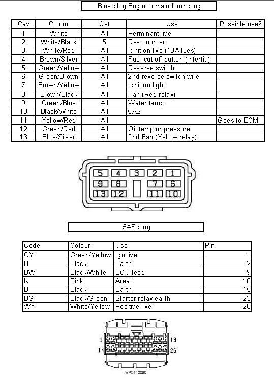
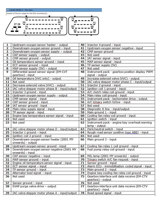
I gave up, searched for the diagrams and came up with these.
5AS
MEMS3 pinout
Soo, got rid of the lot and going to make my own loom... debating sticking the keyfob to the detector to avoid the burden.
But then again, it is an excellent anti-theft device
After giving up on that I ran into some older atom pictures and noted that those didn't have elaborate seat structures.
Given that my seats are cheap-will-do-for-nows and are not self supporting I started playing with the idea of altering the existing set-up.
What used to be...
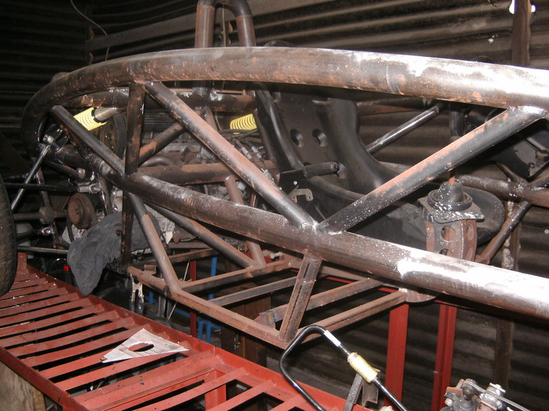
I got get rid of about 30kg of weight while losing some Newtons/degree... since the emphasis has changed to keeping it light, I went for it.
Thinking I would not change the seat position I replaced the old bottom up design for a hanging one.
But then i realized that I had more room under the seats and could get the COG lower... Since we are talking about 200kg of weight fully laden this is
not to be sniffed at dynamically speaking.
The most radical seat position won some 15cm in max. height and some 10 in COG.
Making brackets again.
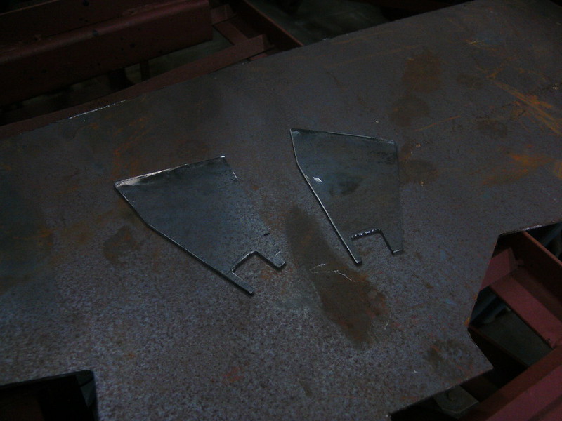
So this is the new position. With this position it is impossible to put weight on the 'hammock' style bodywork. So this is now going to be
lighter, thinner and cheaper to.
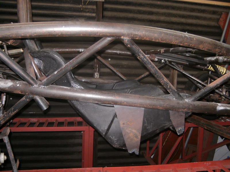
For comparison
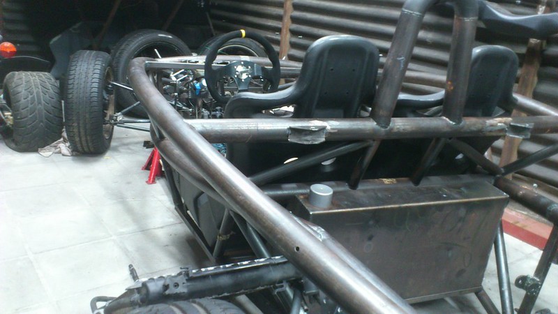
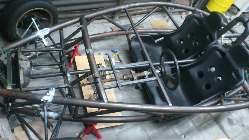
For the gear selector I'm thinking of laminating a bulge in the hammock... or going with a DIY electronic shifter.
Also I have been paining myself over the radiators, they are a packaging nightmare.
Since the now live where a lot of other stuff could be neatly stuffed.
Bought these Polo rads cause they were cheap and the locost standard, but actually to big to live in my nose cone.
Been searching.
CAR l x h x d in mm
Micra K11 1.0 380 X 370 X 17
Panda 45pk 1992 0.9 462 x 240 x 35
Panda fire 1994 520 x 250 x 34
Punto 55 1.1 1993 435 x 322 x 23
Deawoo Matiz 0.8 458 X 294 X 16
Fiat Cinquecento 0.7 31pk 312 X 214 X 24
Fiat Cinquecento 0.9 41pk 248 x 465 x 34
VW polo II 1986 1.0 40pk 380 x 322 x 38
VW polo III 1.0 45pk 430 x 322 x 34
Civic V 1.3 75pk 1995 346 x 346 x 24
saxo 390 x 322 x 23
Opel Agila A 1.0 377 x 378 x 34
Subaru justy 2001 1.3 330 x 350 x 16
Panda 1986 583 x 250 x 34
UNO 1.0 1992 312 x 340 x 32
Alto V 1.0 2000 325 x 360 x 18
swift 1.0 2001 408 x 341 x 34
Now the Cinquecento 0.7 one would be excellent, well 2 of them in front one another anyway.
But they are quite rare, even new, 0.9 was way more popular but it's too wide.
95 Civic Might be the best compromise, looked at rover mini's but they are 5 times the price.
Thoughts anyone ?
Next steps... a complete steering system overhaul
|
|
|
drt
|
| posted on 14/6/18 at 12:47 AM |

|
|
So tonight the steering system
As the geometry changed the location of the steering rack was no longer correct.
And there was the little thingy with the pesky Pauli principle regarding a steering rod and a chassis.
So to keep it simple the steering rods will be in the same plane as the upper wishbone.
This means the inboard pivot point must be on the same point along the X-axis.
Since the steering rack pivot point combo I was using is about 25mm to wide at the narrowest setting it meant...
Bodging time!
Steering rack without pivot points
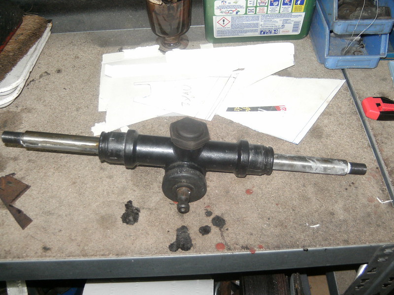
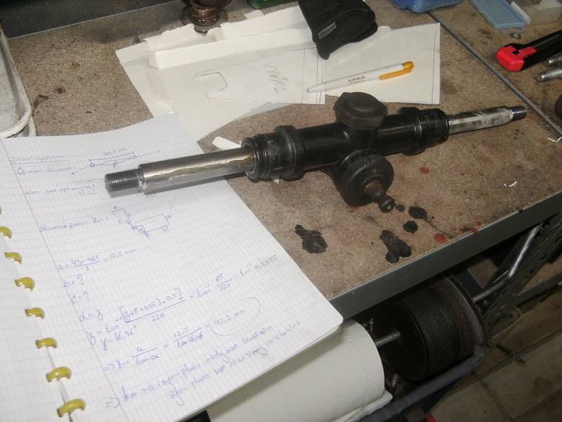
The pictures I took of the process didn't go through for some reason. But is was a simple case of putting it in the lathe,
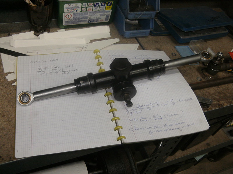
taking out the dial gauge, swearing for an hour to get it somewhere near concentric along its length,
machining off the threaded ends, boring a hole and tapping it.
Result;
Now I'm gonna run some simulations to see if my assumptions regarding the Ackermann and bumb-steer are still correct.
|
|
|
drt
|
| posted on 15/6/18 at 11:44 PM |

|
|
few days of careful progress, calculations and simulations.
Trying to get the steering rack in the best position and minimising bump-steer.
So first some very quick and dirty simulations to check the maths and quickly alter the set-up.
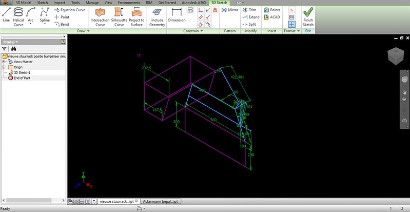
This used to be the home of the rack and rad... it's all on its way out.
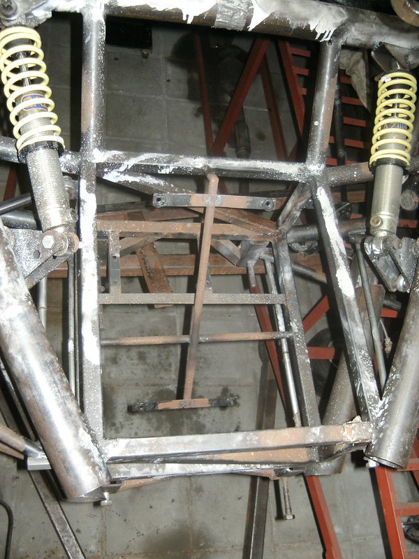
So firstly setting up the rack so it is exactly the width of the top suspension points, done that by putting the bolts through.
Because fabrication tolerances XD
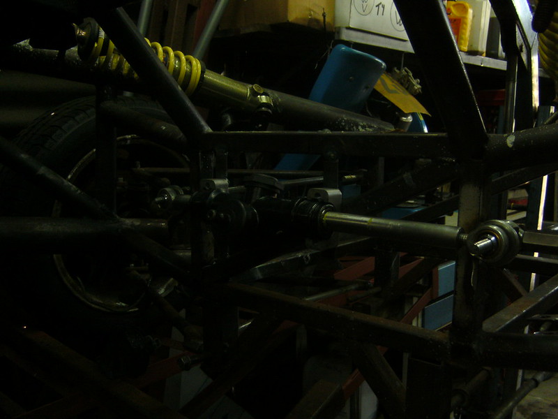
2 little profiles, drilled and installed. Now scribe from the back where it needs to be cut.
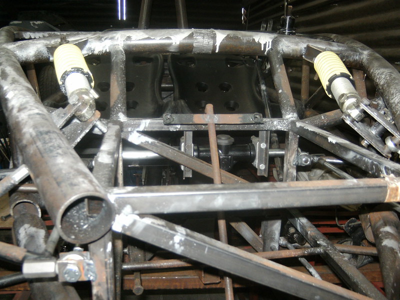
Installed
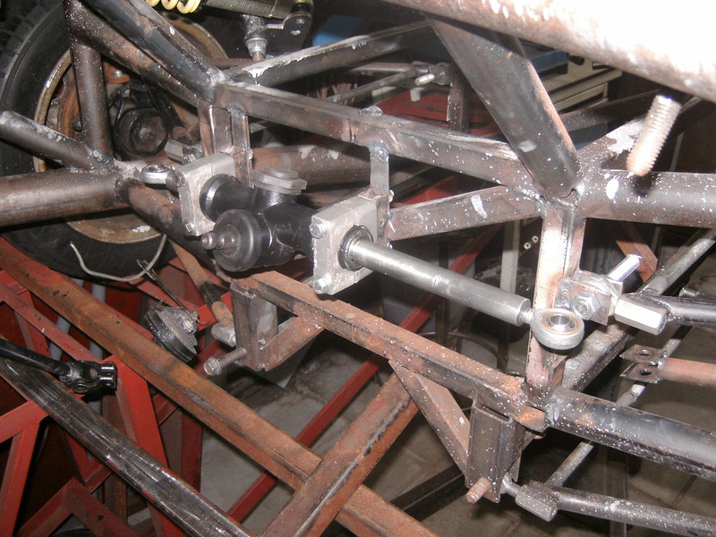
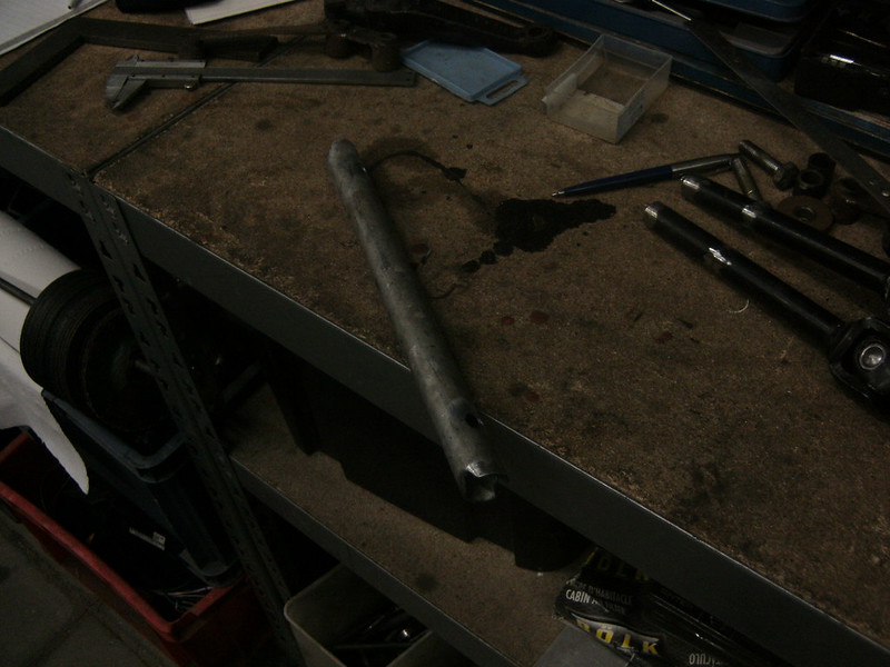
A new steering down tube, with some recesses to increase the weld area and have a mechanical way of transmitting the torque.
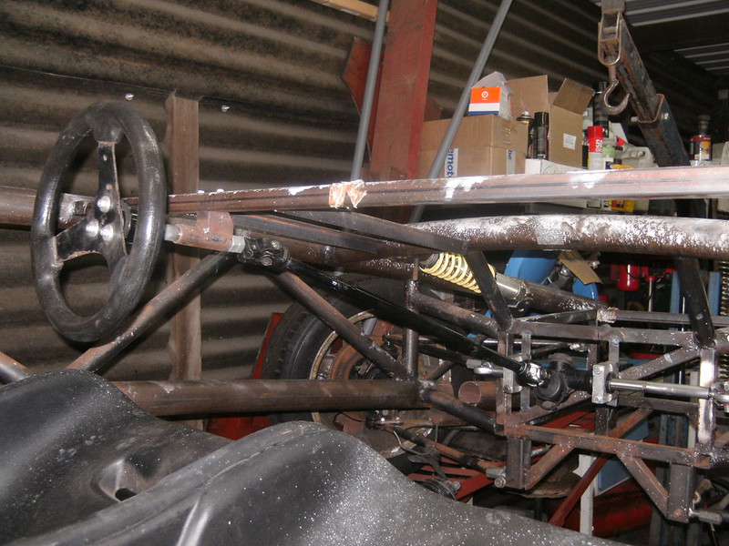
So that is operational, kinda low on pedal box space... but we'll pas that bridge in due time
So now to hide my shame
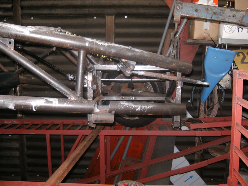
10 minutes of cardboard and 10 minutes of grinding later.
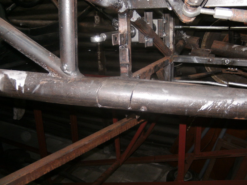
Set the TIG to 11
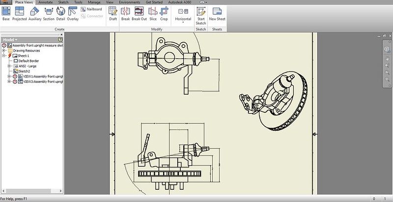
Had a look at the files from way back when... to establish the steering-arm.
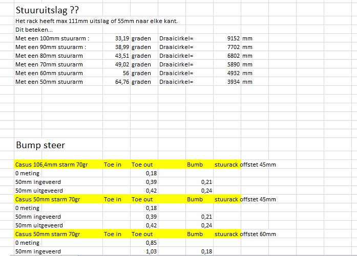
Sorry for the lingo in these notes, I tend to go between a fair few languages. So after establishing the Ackermann angle followed the minimising of
the bump steer and combining that with the space in the rim, I got the lengths of steering arm I could get away with.
This now remains a choice of steering wheel torque vs. turning circle.
|
|
|
drt
|
| posted on 16/6/18 at 09:39 PM |

|
|
Not a lot today...
watching the start of the 24h... and listening to radiolemans in the shed does that to a man.
Hiding the shame on the other side
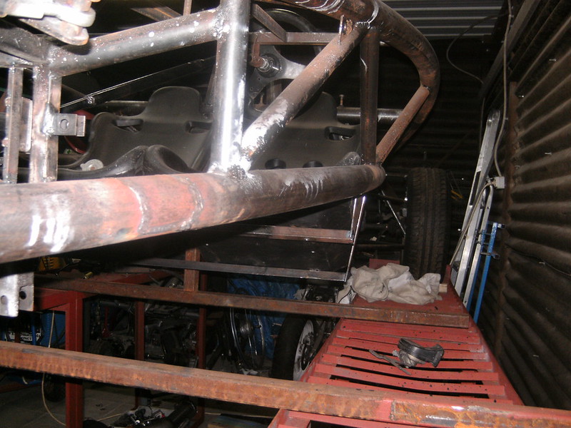
And pulled this out of a the heap...
Mini 1300 high volume rad.
I'm thinking of using it, but I recon it will be on the small side.
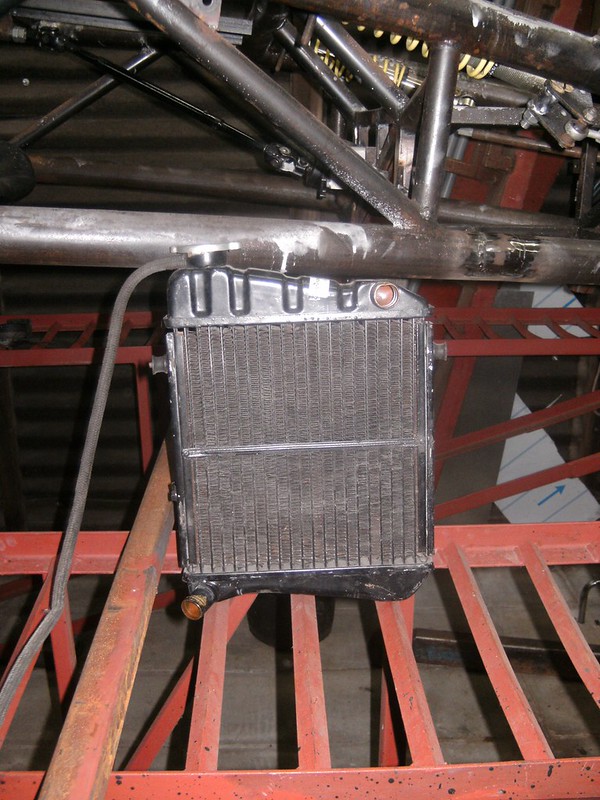
opinions ?
|
|
|
drt
|
| posted on 20/6/18 at 09:30 PM |

|
|
Continuing with the steering arms.
Machined some parts.
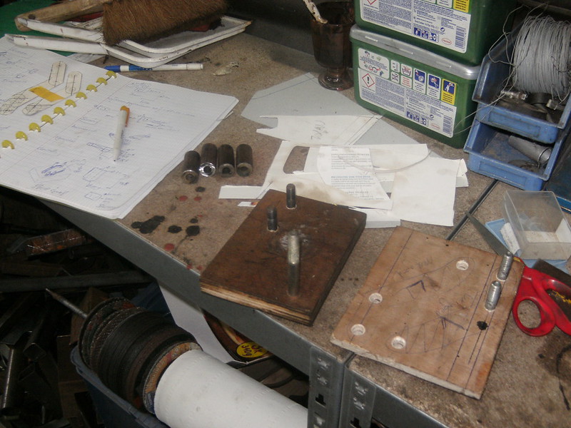
Fixed to a little weld mold. Need some more parts before I can finish them.
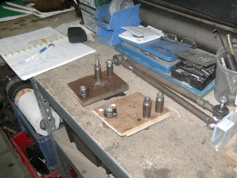
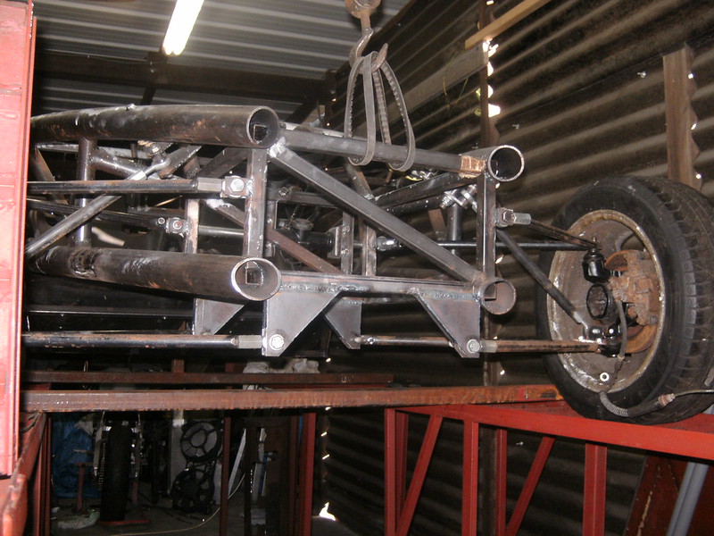
Last new pick up points
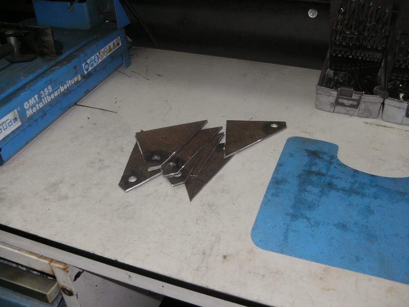
Out with the old
In with the new
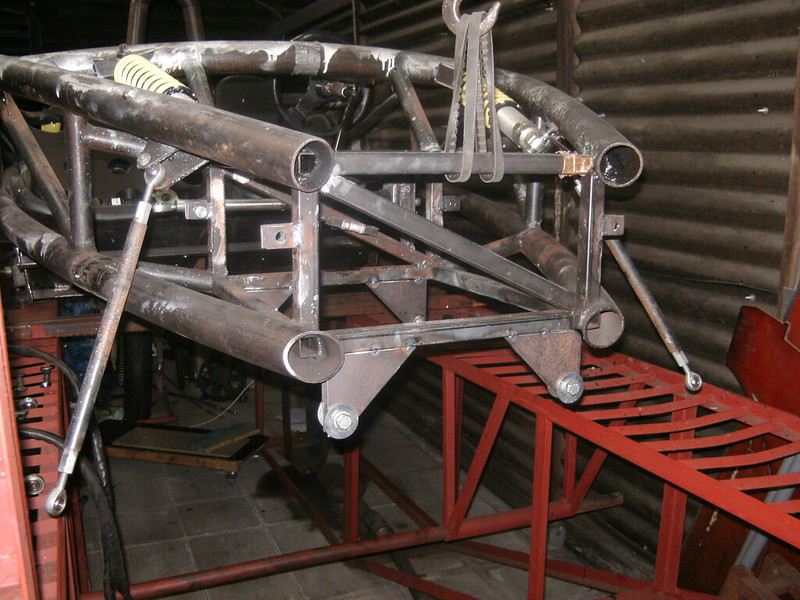
Added sides and done.
|
|
|
AdamR20
|
| posted on 21/6/18 at 08:38 AM |

|
|
You're nuts, I love it!
Rad looks a bit small to me too. Will a Polo one fit? Works fine on my 1800 Zetec with 185bhp.
|
|
|
drt
|
| posted on 21/6/18 at 09:21 AM |

|
|
Thanks... I think XD
Well, I've been down the polo rad road (see above) and it was a packaging+flow nightmare.
The car either needs one just the right size so it fits the front
see...
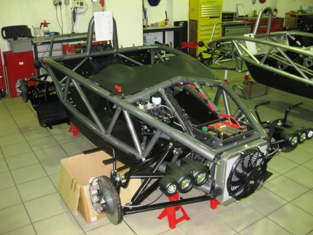
Or in sidepods like the oil coolers of the 500.
Thanks for the reply, I was starting to think people lost hope
|
|
|
AdamR20
|
| posted on 21/6/18 at 09:25 AM |

|
|
Give it a try with what you have, with good ducting and low % of antifreeze it may work. You could also stick an extra bit of cooling in afterwards
(such as a heater matrix or small motorbike rad in a side pod) if needed.
|
|
|
drt
|
| posted on 21/6/18 at 09:35 AM |

|
|
Using the rover K I'm a bit nervous on just trying.
But simulating a radiator is a real pita... there are so many unknowns 
But your heater matrix idea sounds elegant. Small enough to fit in a sidepod and plenty available.
I dismissed matrices because I thought they are high resistance for coolant and optimised for slow air flow, no ?
|
|
|
AdamR20
|
| posted on 21/6/18 at 09:38 AM |

|
|
I'm not certain - but - to me that sounds like a beneficial condition perhaps. If the water spends more time in the radiator it will get cooled
down more I suppose, if it flows through fast it won't have time to cool down!
Edit: Maybe it could be 'branched' off the main coolant hoses a bit like an actual heater matrix to prevent poor flow through the main
cooling system, then have a fan hooked up if there's poor air flow. When I've taken 'normal' cars on track having the heater
on full blast does seem to make a different to water temp.
[Edited on 21/6/18 by AdamR20]
|
|
|
drt
|
| posted on 21/6/18 at 10:25 AM |

|
|
The slower the flow of a heat exchanger, the nearer the temp of the fluid can reach the temp of the air.
But the less efficient it is, it's a case of what you need.
Like a household radiator is huge and slow... so it can give of almost all the heat in the fluid (limited by convection and a bit of radiation).
But a car radiator is optimised for high flow rates of both the coolant as well as the air, so it can efficiently lower the coolant temp from EG. 100
degr C to 80C in a small period of time.
Because the flow rates are very high in the end the total amount of energy expelled is much higher than the slow one, this is also because the heat
exchange rate is not linear.
Q = + (m1)(Cp1)(T1in - T1out)
Q = + (m2)(Cp2)(T2in - T2out)
DTlm = [(T1in - T2out) - (T1out - T2in)]/ln[(T1in - T2out)/(T1out - T2in)]
Q = U A DTlm
It's always a case of the more you know, the less you know 
But nonetheless, still going to try 
|
|
|
drt
|
| posted on 21/6/18 at 09:19 PM |

|
|
DAMN...
Pushed my luck on this one.
The weld mold was insufficient for keeping the parts in place.
Didn't help that the tolerances for the connection with the upright is about 0.5mm
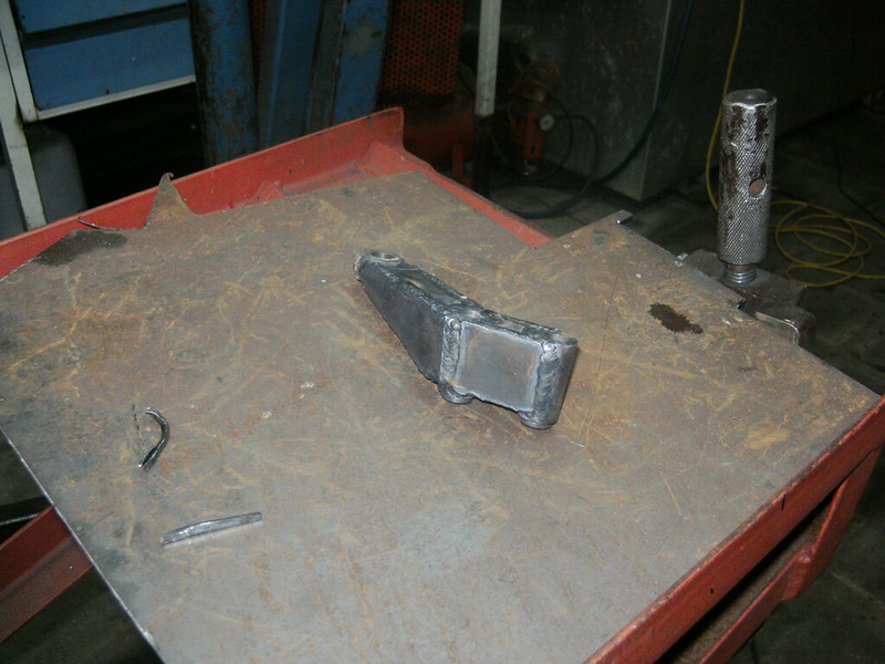
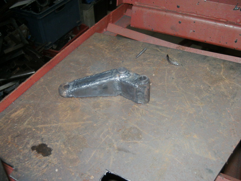
So now I'm going to have to get them milled... a bit of a bugger since it's going to be costly judging by the details.
Ofc everything is relative, but atm the whole project has only cost me around 1200 eur.
Any machinist out there ?
|
|
|
woodsy144
|
| posted on 20/1/19 at 10:08 AM |

|
|
Steering Rack
Hello,
I am interested in your steering rack.
May I ask, where did you source it from??
Make, model, donor, etc??
Thanks
Tim
|
|
|
drt
|
| posted on 12/4/19 at 11:39 PM |

|
|
So after not even being in the same country as the project for a long long time, where back
In last episode, a dog's breakfast steering arm... that didnt work.
now she has 2 machined ones... only 0,1 degree bumpsteer at max deflection and very nice ackermann.
But, in a weird twist of faith, again there is some chassis in the way.
So out with the grinder
[img] 216
(2) by paris r, on Flickr[/img] 216
(2) by paris r, on Flickr[/img]
Some newspaper aided design.
[img] 217
(1) by paris r, on Flickr[/img] 217
(1) by paris r, on Flickr[/img]
Grinded
[img] 217
(2) by paris r, on Flickr[/img] 217
(2) by paris r, on Flickr[/img]
Installed
[img] 217
(4) by paris r, on Flickr[/img] 217
(4) by paris r, on Flickr[/img]
then invented some bracketry to put the alternator somewhere where Rover didn't think off...amateurs
[img]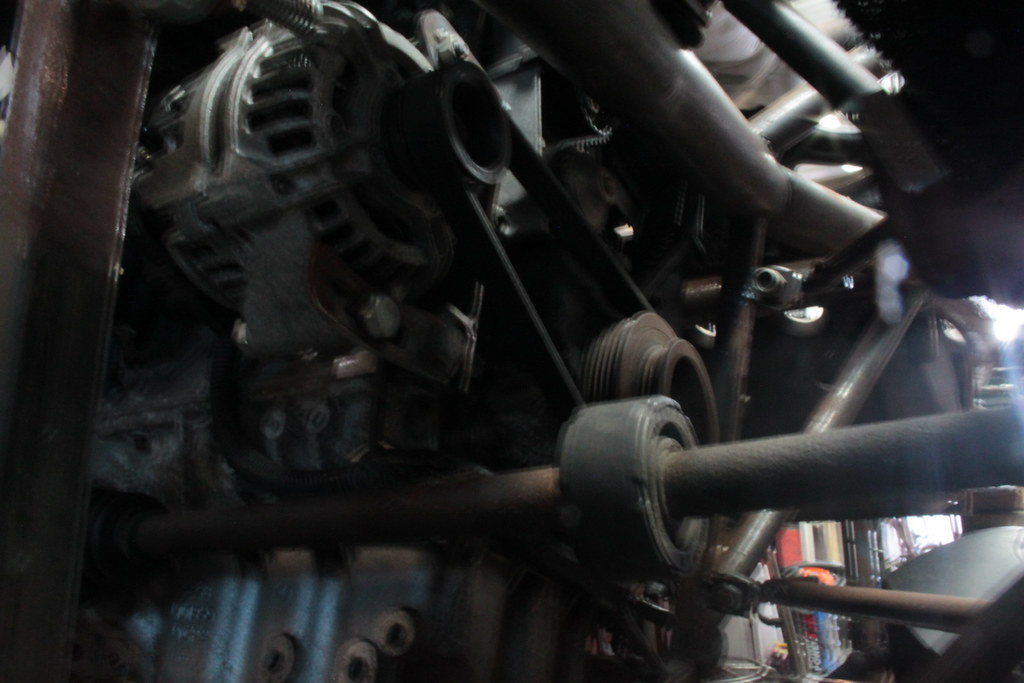 216
(5) by paris r, on Flickr[/img] 216
(5) by paris r, on Flickr[/img]
Exhaust is being rerouted atm, pics tomorrow. Gave me a headache for the longest time, as NA-engines.. you know the drill.
Brake lines are made and ready to go in.
I'm hoping to finish the bl**dy thing now...
wish me luck
|
|
|
drt
|
| posted on 17/4/19 at 07:55 PM |

|
|
Original flanges didn't fit, so made some to work with the OEM gasket.

so that makes the front part...

And then... watching the grand tour Mongolia, I was laughing that the mistaken steering rack position must have been scripted...
Until I found out that I did so too months back... pays to sometimes sit in it and make noises. So new steering rack position requires new
mounts...

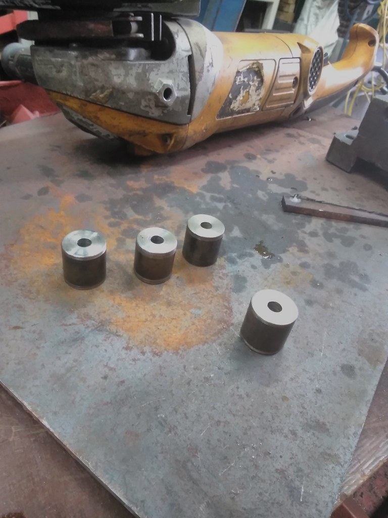
Spacers
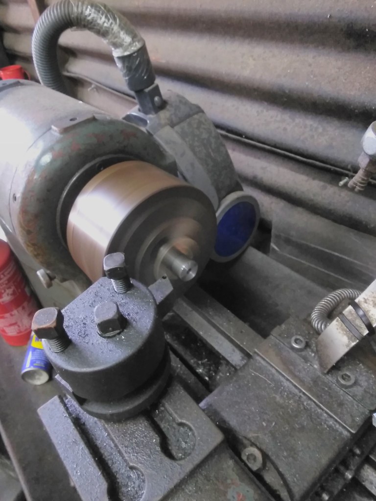
so all together...

Positioned correctly,

Installed

lovely jubbly

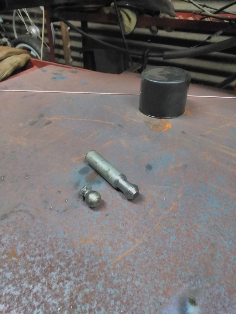
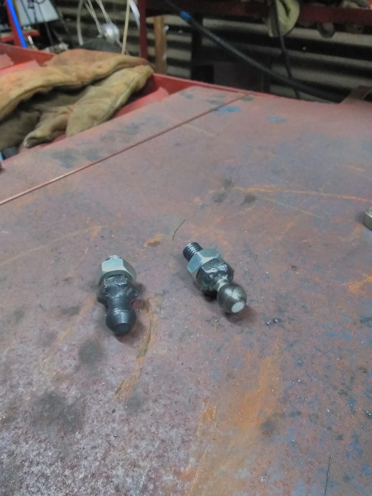
So on with the gear shift... found out the MG F cables do not fit the Rover 45 gearbox ball joints... what a joke! It's the same friggen
gearbox.
Looked to get some locally, no dice. Looked on the confuser... 15 QUID !!! for 1. So I set out turning one

Horrible job, but it works... spare the phallus jokes
 [url=https://flic.kr/p/2fz2ade] [url=https://flic.kr/p/2fz2ade]
So now onwards to instal the gearshift.
|
|
|


