theprisioner
|
| posted on 11/4/12 at 08:50 PM |

|
|
Puma/Sigma fitted to J15 - cooling pipes
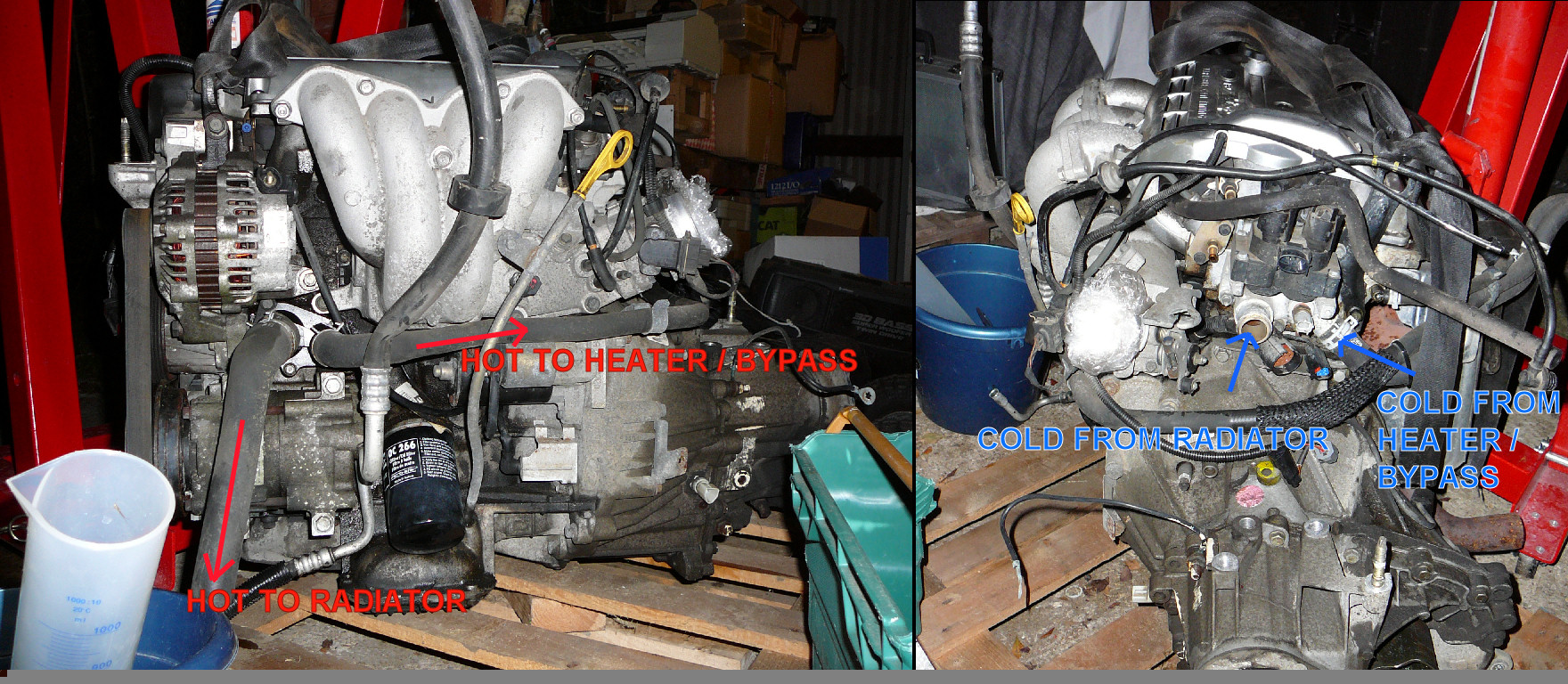
Can annyone help with either pictures or a hand drawn diagram or better of how the hoses run from a Puma 1.7 vvti (Sigma) engine to the radiator. I
appear to have two pipes up near the thermostat and two pipes below the alternator. Can anyone designate these?
|
|
|
|
|
nickm
|
| posted on 11/4/12 at 09:18 PM |

|
|
Hi
The large at each is the rad in and out 32mm, the small 19 or 22mm ? is the bypass for when the engine is cold it keeps circulating the water without
the radiator being used until it reachs operating temp.
Pretty sure your 1.7 is the same as my 1.6 the previous phots for the tank fm monkey arms shows the routing.
How fast are you building it !!!!!! (or how slow am i)
Nick M
|
|
|
Madinventions
|
| posted on 11/4/12 at 09:55 PM |

|
|

FYI: the thermostat is behind the plastic casing below the alternator, not up near the coilpack.
I have an expansion tank on mine that is t'eed into the lowest point of the 'cold from radiator' pipe. I used the tank from a MK3
Golf (iirc?).
Hope this helps,
Ed.
Mojo build diary: http://www.madinventions.co.uk
Solo music project: Syrrenfor http://www.reverbnation.com/syrrenfor
View my band website:
http://www.shadowlight.org.uk
http://www.eastangliankitcars.co.uk/
|
|
|
Madinventions
|
| posted on 11/4/12 at 09:56 PM |

|
|
I should also say that if you're not fitting a heater, just connect a hose between the two small fittings. Don't just cap them off!

Ed.
Mojo build diary: http://www.madinventions.co.uk
Solo music project: Syrrenfor http://www.reverbnation.com/syrrenfor
View my band website:
http://www.shadowlight.org.uk
http://www.eastangliankitcars.co.uk/
|
|
|
theprisioner
|
| posted on 11/4/12 at 10:33 PM |

|
|
Heater and other pipes
Unfortunately in Scotland we are a few degrees cooler here, I am planning on fitting a heater. Also the header tank has an overflow, where does that
go in a modern engine arangement?
|
|
|
Madinventions
|
| posted on 11/4/12 at 10:46 PM |

|
|
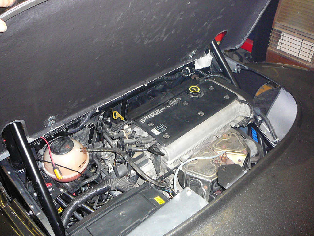
Mine is like this...

Note that this is my old 1.25 engine, but the 1.7 is pretty much the same.
Loads more photos in my website (see below).
Mojo build diary: http://www.madinventions.co.uk
Solo music project: Syrrenfor http://www.reverbnation.com/syrrenfor
View my band website:
http://www.shadowlight.org.uk
http://www.eastangliankitcars.co.uk/
|
|
|
theprisioner
|
| posted on 12/4/12 at 05:37 PM |

|
|
One last question
Thanks for all the really useful info, one last question. From Madinventios picture the overflow goes into the head in a custom site. However how
exactly is the header tank (feed/lower) connected, I assume to the manifold beneath the coil pack that also goes to the radiator top pipe? I assume
some sort of special pipe T etc?
|
|
|
nickm
|
| posted on 12/4/12 at 07:31 PM |

|
|
Hi
I just put a purpose built T fm Car builders/rally design etc in the bottem pipe one of the types with the temp sender housing for instruments later.
The temp sender for the ecu i used the housing near the overflow/breather pipe as the ecu would then now when the engine was cold on initial start up
(ie the bypass) and be able to compensate.
Nick M
|
|
|
Madinventions
|
| posted on 12/4/12 at 09:08 PM |

|
|
I used this CBS 'tee' (link), and I put
it at the lowest point in the return pipe from the radiator to the 32mm inlet near the coilpack, and fed a 15mm pipe up to the bottom of the tank. I
have 3 Zetec engines here (1.25, 1.6 and 1.7) and they all have the 'custom site' for fitting this hose on to.
In my layout, the 32mm pipe from the waterpump/alternator side goes to the top of the radiator, and the cold return flows from the bottom back to the
'coilpack' inlet. There are probably 100 valid reasons why this should be the other way around, but this orientation made the pipe
routing much easier for me and hasn't caused any problems at all. The engine temp sits at 90° all the time when driving, and takes 10-20
minutes in stationary traffic to reach 104° which turns the fan on, and this brings it back to 99° in less than a minute.
The temperature sender for the Zetec SE is in the top of the cylinder head between the middle pair of spark plugs, and I use this with the original
Ford ECU. However, I did also fit one of the mentioned 32mm adaptors with a tapped hole for another sender
(similar to this), and I put this in the top hose (hot one)
near the radiator. This feeds a standalone temperature gauge on the dashboard. Therefore I have 2 temperature gauges in my car, 1 for the actual
engine temperature, and one for the water temperature which proved very useful when I was diagnosing a stuck thermostat!
Ed.
Mojo build diary: http://www.madinventions.co.uk
Solo music project: Syrrenfor http://www.reverbnation.com/syrrenfor
View my band website:
http://www.shadowlight.org.uk
http://www.eastangliankitcars.co.uk/
|
|
|
johnH20
|
| posted on 13/4/12 at 08:53 PM |

|
|
I am probably a bit dumb but I always thought that hot water came out of the cylinder head via the thermostat and that cold water came into the block
via the pump. Seems to be against basic thermo dynamics that it should be the other way round. Or am I missing something?
|
|
|
theprisioner
|
| posted on 13/4/12 at 10:10 PM |

|
|
Good set of articles to illuminate debate
see: http://www.emeng.gentlyhosting.co.uk/Cooling/Part1.htm
change Part1 to Par2 etc or press the button at the bottom for the full set of 5 articles.
It would appear the Sigma has the thermostat in the return path the pump is just beyond the thermostat and the high point in the engine is connected
to the top radiator hose. All slightly counter intuitive to me.
Whish you entertaining reading.
|
|
|
Madinventions
|
| posted on 13/4/12 at 11:32 PM |

|
|
The Zetec SE (Sigma) is a very different beast to the 'standard' Zetec described in that article, but it is entirely possible that
I've got the flow marked backwards in my photos (I'm no Ford engineer!) It just makes sense to me that the thermostat is at the hot end
of the plumbing. I'll feel the pipes next time I've got the Mojo running and double check to be sure!
Anyway, the way I've got mine plumbed in works really well so it's a suggestion of a good place to start. 
Ed.
Edited to add:
There's a graph of real engine coolant temperature data from my car at the bottom of this page:
Link to my build pages
[Edited on 13/4/12 by Madinventions]
Mojo build diary: http://www.madinventions.co.uk
Solo music project: Syrrenfor http://www.reverbnation.com/syrrenfor
View my band website:
http://www.shadowlight.org.uk
http://www.eastangliankitcars.co.uk/
|
|
|
Madinventions
|
| posted on 13/4/12 at 11:48 PM |

|
|
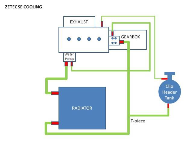
Just found this diagram in this older thread: Link
 
Zetec SE Cooling
Looks the same as my plumbing. 
[Edited on 13/4/12 by Madinventions]
Mojo build diary: http://www.madinventions.co.uk
Solo music project: Syrrenfor http://www.reverbnation.com/syrrenfor
View my band website:
http://www.shadowlight.org.uk
http://www.eastangliankitcars.co.uk/
|
|
|
johnH20
|
| posted on 17/4/12 at 01:13 PM |

|
|
I am sure that circuit is right Madinventions as it is the same as installed in my Puma. The thermostat is attached to the head and I am sure that the
water comes out of that and returns via the pump not the other way round. Most importantly yours works - and I hope mine will too shortly!
|
|
|
theprisioner
|
| posted on 19/4/12 at 07:49 PM |

|
|
I dd it my way!
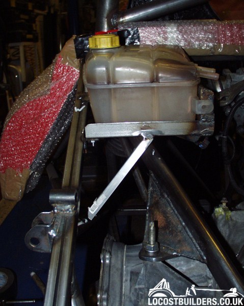
The Focus MK1 header tank appears to meet the challenge, only time will tell the truth.

The mounting bracket is attached to the chassis, I wanted to avoid mounting it on the engine support hence the complex bracketry.
I am happy to wire up the pipes as per the advice given in this forum as it works!
Comments good or bad welcome.
|
|
|
nickm
|
| posted on 20/4/12 at 05:38 PM |

|
|
Hi
Ref cooling pipes i did mine the same as my Puma 1.7 which is the same as Madinventions, can remember thinking at the time it wasnt the logical route
but Mr Ford couldnt be wrong, did 50,000 thrashed miles in it with no probs.
Header/expansion tank very similar not on the engine mount but the back of the seat chassis tubes used a VW round one then realised that the ali
bracket wouldnt be strong enough so added another ali bracket below with a threaded rod propping it up (i hope).
Nick M
|
|
|
stevebubs
|
| posted on 20/4/12 at 05:51 PM |

|
|
quote:
Originally posted by theprisioner
Unfortunately in Scotland we are a few degrees cooler here, I am planning on fitting a heater. Also the header tank has an overflow, where does that
go in a modern engine arangement?
T into the highest point in the system to aid bleeding.
|
|
|
I predict a Riot
|
| posted on 26/5/12 at 09:28 PM |

|
|
I have the same arrangement as you - 1.7l Sigma in a J16.
I ran the engine up to temperature for the first time the other day and the pipe from beneath the coil pack definitely gets hot first when the
thermostat opens, therefore the pump must be sucking.
Hope that helps.
This thread had got me doubting my plumbing fotemperatures
[Edited on 26-5-12 by I predict a Riot]
|
|
|
theprisioner
|
| posted on 27/5/12 at 07:30 PM |

|
|
Thanks
That is very useful info. I have a westfield and frankly it is over cooled in winter and never realy get up to temperature rapidly. This week is the
exception. I was just trying to avoid any known pitfalls. I doubt it matters which way the water runs as long as the system performs it's
function. Nice to know what direction the pump runs to start with though. Thanks again and let me know how you get on on a run?
|
|
|
johnH20
|
| posted on 28/5/12 at 07:47 PM |

|
|
For the benefit of 'theprisoner' but not directly related to this thread there is a 'known' Westfield (over)cooling problem
with Zetec engines. Check out http:westfield-world.com under cooling. There is a specific article at www.emeng.gentlyhosting.co.uk specifically on
this. Hope this is of interest.
|
|
|
SylvaJ15-02
|
| posted on 16/8/15 at 10:11 AM |

|
|
This thread has been really useful in sorting cooling problems of my J15. I have a 1.7 puma engine on throttle bodies and a polo radiator and only
recently got the car IVA'ed.
I got the Emerald mapped pre IVA and it was commented that the engine ran hot and during the IVA, it boiled over during emissions test (resumed the
test after leaving to cool and just scraped through)
Since getting the car on the road 6 months ago I've been trying to sort out the bugs. First off I found the radiator cap was faulty as it
wasn't airtight so the system never pressurised. After fixing that, according the ECU and temp gauge, it runs hot (95-100 when cruising)
I replaced the thermostat - no impact
Changed the water pump - no impact
inserted a restrictor in the heater bypass hose - no impact
Compared the pipe routing to internet sources - mine was the same - hot water out from the engine (coil pack end) goes to the top of the rad
(https://www.youtube.com/watch?v=V7inC4lOpGs - nice and simple :-) ) - so it must be right
Looking at madinventions diagram - the hot water goes to the bottom of the rad. I compared it to some pics of my Fury of years ago and that too had
the hot water going to the bottom of the rad (still regret selling that - it was brutally quick)
I rerouted the piping so hot goes to the bottom the rad - it now works fine!! near constant 85 on the gauge
So, since the engine and rad have long pipes between them, I'm wondering if the more efficient route is for hot water to go to the top of the
rad, but maybe the puma waterpump is incapable of pumping hot water that far?? the reason why it works with hot going to the bottom of the rad is that
there is a benefit of convection where the hot water more redily rises through the rad rather than the pump pushing it the other way - dunno!
lastly, I bought correct tools to align the cams and a lock for the crank - after several hours fiddling, it got them perfectly aligned - both came
were retarded - the car goes rather better now!
|
|
|
Ugg10
|
| posted on 16/8/15 at 11:58 AM |

|
|
Really interesting, I am just about to start plumbing in my 1.7 puma engine into my anglia. So if I get this right, I can connect the large connector
on the side of the block to the bottom of the rad and the one at the top of the head to the top of the rad. If this works ok then this would simplify
my routing alot. My only question then is which pipe do I t into for the header tank, the lowest one I presume?
---------------------------------------------------------------
1968 Ford Anglia 105e, 1.7 Zetec SE, Mk2 Escort Workd Cup front end, 5 link rear
Build Blog - http://Anglia1968.weebly.com
|
|
|
theprisioner
|
| posted on 16/8/15 at 12:48 PM |

|
|
The Madinventions diagram is correct I believe
http://sylvabuild.blogspot.com/
http://austin7special.blogspot.co.uk/
|
|
|
Jenko
|
| posted on 17/8/15 at 03:24 PM |

|
|
My cooling system is also identical to madinventions pic. J15 running throttle bodies on a standard puma engine. Currently running at 156bhp. No
heater (pipes just joined together) Water pump was changed before installation as was the thermostat. Runs rock solid at 88 degrees even after
enthusiastic driving. Engine set up at Northampton motorsport.
A couple of things to check....thermostat is in correct way around, engine is not running so lean that the cooling system can't cope. Ideally,
you would want to see AFR plotted over the rev range to ensure the cam switching (VVT) is not causing issues with the mapping.
But I can confirm that the pump can easily push the water around the system....
[Edited on 17/8/15 by Jenko]
MY BLOG - http://westfieldv8.blogspot.co.uk/
|
|
|


