suparuss
|
| posted on 23/7/05 at 07:54 PM |

|
|
Its started!
i knew itd happen iventually, finally started building the car today by modifying my audi uprights.
im building a mid engined scratch build using an '86 audi coupe gt with 5 cyl 2.3 litre as a donor.
to celebrate i thought id post the days work!
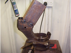
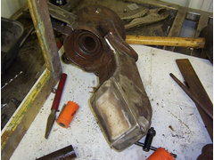
here is how it all started, very rusty front hub soon to be a rear hub since the engine is going in the back of the kit car.
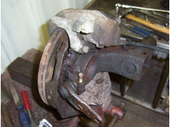 
straight off the car
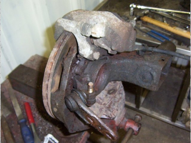
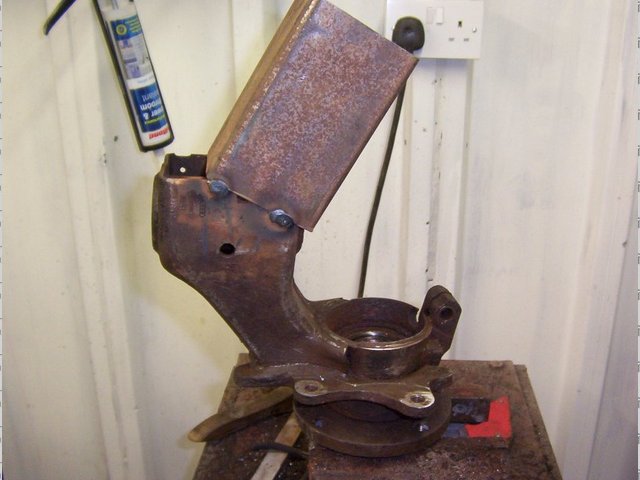
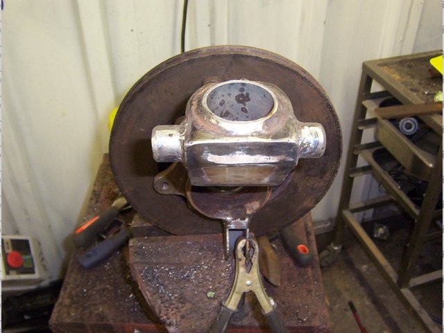
stripped down and all cleaned up, notice how part of the suspension strut is built into the upright, bizzarr!
cleaned up a bit
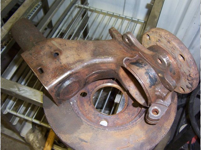
no turning back now, i cut some of the body away to make it a bit lighter and a more efficient shape for my purposes-
thank god for the bandsaw
heres how i did it, there was no way to clamp it in the band saw so i welded a piece of box section for something to clamp in-
modern art
heres the bandsaw in action, like hell i was gonna cut through that with the hack saw!
 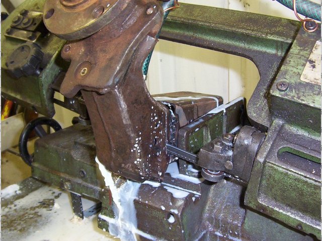
cutting
the next step was to make a mounting for the bottom wish bone. due to the shape of the upright i decided to use one rod end at the botom and two at
the top, contrary to the norm where you have two at the bottom and one at the top. shouldnt make much difference.
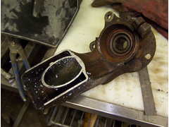
heres the odd shaped monting to go over the existing bottom ball joint mounting, i was going to use the existing mounting but after 10 minutes of
staring at it and some measuring it seemed that the rod end would be too high and would foul the cv joint on the drive shaft-

and here it is welded in place, the holes are just preliminary untill i decide what size rod end to use, probably a 5/8 i think.

and thats about it for today, tomorrow ill finish the other side and paint them up, i havent decided what to do with the top mountings yet, but they
should only really need a hole going right through the top for a bolt to go through for the two rod ends. ill probably seal the back where the cut was
made with some more steel to make em a bit stronger too.
hope you all enjoy the pics and all the fun to be had in the future!
Russ.
|
|
|
|
|
nick205
|
| posted on 23/7/05 at 11:12 PM |
|
|
Russ,
Looks like you have a good range of machinery and skills at your disposal and sounds like an interesting project too.
Are you mounting the engine transverse?
If so does the extra length (width in transverse layout) cause any problems with suspension layout?
Nick
|
|
|
sgraber
|
| posted on 23/7/05 at 11:16 PM |
|
|
I think it's a really exciting time to actually make those first cuts and welds. Congrats! It looks like it's going to be a well powered
car. Any specifications to tell us about? wheelbase, width, projected weight? I assume you are going to keep the engine and transaxle in their
original longitudinal configuration? That should work well IMHO.
Keep us in the loop.
Steve Graber
http://www.grabercars.com/
"Quickness through lightness"
|
|
|
suparuss
|
| posted on 23/7/05 at 11:50 PM |
|
|
cheers guys, this has been my dream for a long time so im really happy to be starting finally. i love working with metal, although im a joiner by
trade ive always preffered working with metal than wood, funny how things work out!
any way, im keeping the engine longitudinal, when i had the audi on the road i loved the way it shakes the car from side to side when you rev the
engine and you dont get that with transverse mounting, plus i think they look better in the engine bay when oriented that way.
i havent fully designed the suspension (or any of the rear end for that matter) i need to get my finger out and measure the engine, but ill be taking
it out soon to rebuild the head and also to take proper dimensions for cad, but i cant see suspension layout being a problem as ill be having rocking
top wishbones and horisontal shocks, so they should sit just above the transmision.
nothing is really set in stone yet until ive finished the uprights and drawn them up in cad, and the same with the engine, then ill design the rest
around that.
i first designed the chassis about a year ago to take a bike engine but ive since changed my mind to using hte audi (was one my other options at the
time) and have been renovating my house ever since (which still isnt finished!) but im cracking on now so progress should be good.
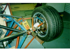
heres how the chassis looks in a very preliminary state, still to take a bike engine but shouldnt need much change.
[img][/img]
|
|
|
Lotusmark2
|
| posted on 24/7/05 at 04:59 AM |
|
|
Looks very interesting mate, really looking forward to seeing how this moves on!
|
|
|
suparuss
|
| posted on 24/7/05 at 09:07 AM |
|
|
thanks lotusmark2, i see you are using a vtr1000 engine? i was going to use one of those when i first started this project but ended up selling the
engine to a scottish fellow on here, wonder if you ended up with it?
you can see the basic outline of the v twin top right of the pic 
|
|
|
Lotusmark2
|
| posted on 24/7/05 at 10:48 AM |
|
|
Mine is coming from the font of all engines Colibriman.
Yeah using the VTR for light weight and loads of torque (the sound is just a bonus)
|
|
|
shades
|
 posted on 24/7/05 at 06:26 PM posted on 24/7/05 at 06:26 PM |
|
|
the audi 5 pot will sound the business :-)
|
|
|
Fred W B
|
| posted on 24/7/05 at 07:55 PM |
|
|
Hi Russ
Chassis looks very good.
I am also using the audi gearbox in my project, but with a Rover V8.
I also started out modifing up the Audi hubs to make rear uprights, as mocked up here
 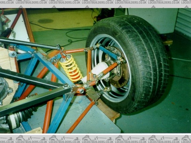
Rear Suspension mock up
I have since cut everything off the hubs, and am going to fabricate completely new uprights around the Audi central boss.
What is the wheel base of the car going to be? The 5 cylinder is a rather long engine and I battled to get the steeringrack/pedals/driver/seat/Rover
v8/gear box into a 2400 mm wheel base.
Will follow your project with interest.
Cheers
Fred WB
|
|
|
suparuss
|
| posted on 24/7/05 at 09:21 PM |
|
|
nice one, i have a couple of q's for you then fred!
firstly, are the bearings on these hubs supposed to wobble from side to side? if not i need new bearings! they were ok untill i took the calipers off
which were obviously stabilising them a bit.
also have you used all the original drive train with not modifications? (apart from the uprights obviously) and how wide is the car?
its a strong looking chassis youve built, almost looks like it would survive re-entry!
ive just checked in cad (thats tricky cos i cant run cad on my normal system cos of some sort of error so have to reboot with another hard drive to
use cad) and my weelbase was originally 2330mm but i doubt that will work with the audi engine.
Cheers,
Russ.
|
|
|
Fred W B
|
| posted on 25/7/05 at 08:26 AM |
|
|
Hi Russ
Bearings - Mine had very little movement and the hubs had to be pressed out. Remember that toe control is very important on the rear, any movement at
all will upset the handling big time.
Drive train - No mods, apart from what needed to be done to connect to the Rover V8, although I haven't sorted the gear linkage yet. Some of the
right hand drive GT40 boys apparently modify the shift actuating output so that it comes out the right hand side of the box, and connects to a cable
set up. I am going to try to get a mechanical linkage to work with the standard shift output currently on the left top of the box.
Car Width - If you don't modify the drive shafts, it depends on the offset of the rear wheels. Currently my width over rear wheels (w.o.w.) in
my mockup with standard drive shafts and 8" rear wheel with almost zero offset is about 1950 mm, too wide? Things like a Ferrari F40 are about
1990 mm w.o.w, Radicals about 1790 w.o.w, original T70/GT40 about 1750 mm w.o.w, so looks like I will have to shorten the drive shafts to get an
overall body width of 1800 mm. Sorry to be a bit vague, am at work now and my notes are at home. Anybody else care to comment on desired middy w.o.w?
I quote w.o.w while most quoted specs give track, to which you have to add 2 x (half a wheel width less offset) to get overall width which gets
complicated when you don't always know the offset used.
Chassis- Still a prototype, see http://www.locostbuilders.co.uk/viewthread.php?tid=22142
Cheers
Fred WB
|
|
|
Alan B
|
| posted on 25/7/05 at 03:13 PM |
|
|
Good start mate.
It helps all of us to be further inspired to continue what we have started.
Keep keeping us up to date.
Alan
|
|
|
sgraber
|
| posted on 25/7/05 at 04:16 PM |
|
|
Isn't the magic track to wheelbase ratio 1.6:1? So if you are running 2400mm wheelbase, you would be looking at a track of 1500mm (hub faces).
That's not w.o.w. though, so add the outboard offset x2 and you are going to be in the ballpark.
Graber
Steve Graber
http://www.grabercars.com/
"Quickness through lightness"
|
|
|
turbo time
|
| posted on 25/7/05 at 06:40 PM |
|
|
Very nice...another project I'll be watching with anticipation .
The Projects: www.absurdcars.com
|
|
|
suparuss
|
| posted on 25/7/05 at 07:51 PM |
|
|
thanks for the kind words everyone. and for the info fred and steve.
its interesting actually, i thought id have to extend the shafts a little to get a decent width since i like the style that comes with having those
wide torsion boxes down the sides of the car. the track on the original car is 1400mm at the front and full width is 1681mm so its not that far off,
can probably make it up with having wider wheels and maybe spacers as well.
the uprights are nearlly finished now, taking a little longer than i expected. i decided to put some decent size lugs for the top mounts instead of
just drilling a hole, seems a higher quality approach and also being wider should make it more stable.
anyhoo heres a few pics-
heres that cut covered up with some 1mm steel, not really structural, just to cover the hole to stop water and road crud filling it up.
nothing like a good stitch up
i drilled a hole for a tube with nuts welded in each end to go through, ill drill the nuts out to the size i want later when i know what size bolts
will go through. the hole is a bit oversize to allow adjustment when alligning it properly.
 
big hole in preperation for to
and here it is all welded up.
and again
i allready plugged the hole in the tops and the other sde is almost finished then its a lick of paint and bobs yer aunties uncle!
there are more pics in my archive aswell.
|
|
|