drt
|
| posted on 24/4/19 at 11:05 PM |

|
|
This post I scaled down the resolution of the embedded pics... because the big ones are hard to get an overview IMHO.
Please let me know if you want them big again or this is better. Thanks
So since I had some assistance I put it to work on the battery tray

Because thatīs going here, for weight distri

Making it stiffer with some flanges

tricky to weld as itīs less than a mm sheet

now to combine: added support for the battery + a, laterally stiff, jacking point + support for the nose cone

All done;

bending a try-out for a selector cable bracket
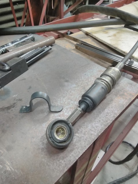

Lower selector

And the upper one

|
|
|
|
|
drt
|
| posted on 5/5/19 at 01:04 AM |

|
|
this week...
Gear selector deja vue

and some more 'deja'

Lathed a bushing, since I had to elongate the OEM shifter cable... the system is done some more pics next time

On to a hot potato... with cooling
This has been a point of debate over the last few weeks... months even. Where to put the rad.
History has told us that putting them in the nose either requires custom rads = don't have the funds for that and K's like a short cooling
route
Or a huge waste of space (by being in between the dampers) = want to use it for electrics etc
Pontoons = needs either custom or motorbike rads and require the build of a model+mold+product
So I preferred it in front of the engine sucking air from underneath ( apparently the new atom has such a set-up) = need a new fuel tank and the flow
underneath is probs not laminar so quite a huge duct would be sticking out underneath... and trial fits pointed out that there is little room for a
fan
Exhaust ? I'm wrapping it and using the OEM heat shield...
Another solution would be scooby intercooler style, using the airbox to duct air to it... CFD made me nervous about the outflow of air between de rad
and the engine.
Even having the rads parallel to the car and ducting air in (Honda VTR style) was considered.
In the end I came to a compromise having the rad at shoulder height between the occupants, aided by air ducted by the air box.
This way there is good flow, room for fan+ducting, a short cooling circuit and no need for extra bodywork.

So, OEM rad mount rubbers in need of a home

Just put a sock'n'et


Polo rad mounting not readily compatible with those rubbers

And now it is
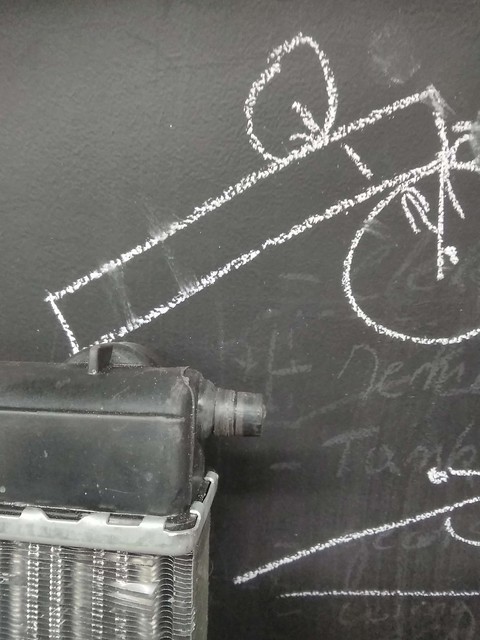
Upper mount, captive nut plate

Some pieces of angle grinded steel

Holed and bent (attempt 99999)

Factory ...XD

|
|
|
drt
|
| posted on 9/5/19 at 10:37 PM |

|
|
Out with the selector for some final tweeking... titled: tweeking_9.5_finalversion_7... if you catch my drift
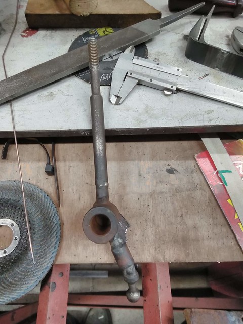
Just to prove that many parts go through many many iterations off camera... here is a rad shroud i spent several hours on and than binned

Just realised I have not taken a pic of how the rad shroud ended up 
This is how the selector ended up, it's light and stiff this way... and fits the seats.

Than hours of trial fitting the paddles to make m fit 'just so' ... so here is the bracket

Foot rest

Fitted

As by magic... here is the master cilinder


|
|
|
drt
|
| posted on 10/5/19 at 01:07 PM |

|
|
As promised...
a dirty deed, done dirt cheap
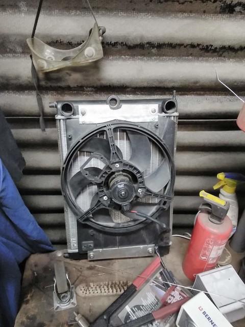
I've posted a question in 'donor parts'... any help greatly appreciated
|
|
|
drt
|
| posted on 14/5/19 at 11:01 PM |

|
|
For simplicity I decided to use the rover master+slave clutch cylinder this called for a remake of the pedal box

Stiffer, lighter and more elegant

So something came in the post today...

So I was ...wrapping to the beat...

In situe

Some brackets and a heat shield later I'm confident that this area (and thus the rad and fuel tank) will stay cool

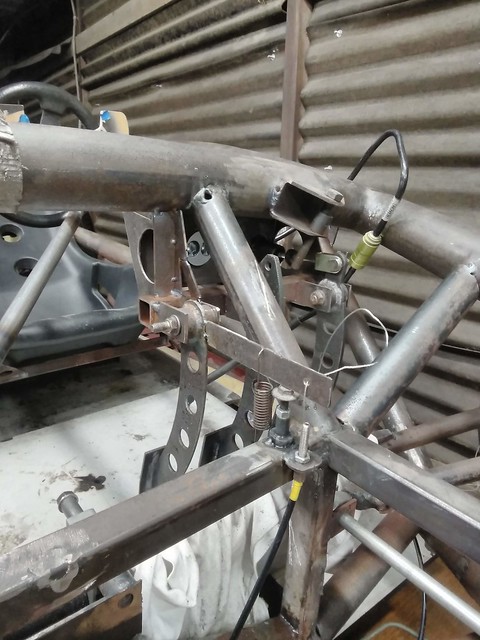
Everybody had me doing the run around, as no OEM throttle cables are long enough. In the end I bought the correct length outer cable from the bicycle
repair shop who has the stuff on a 1000m spindle and bought some steel wire in the DIY shop.

I had always planned on running the cable like this and was very happy with the snazzy bracket for a while

Then it came to my attention that the travel of the rover throttle body is quite long and so the throw on the accelerator pedal was too much
(can't go higher to get less throw as it will stick out over the bodywork).
So I elongated and rotated the lever 90 degrees and came out to this compromise... a bit sad that it isn't snazzy and that the cable operation
now lives where I planned my electrics and shopping compartment...
|
|
|
drt
|
| posted on 20/5/19 at 10:24 PM |

|
|
This week...
I'm still investigating how to connect my master and slave clutch cylinders... I've posted the question in the donor parts section.
ATM the prefered solution is to get some 4 or 5mm flexible hydraulic tube (6mm fitting) and use jubilee clips... some hydraulics guy told me that
should do.

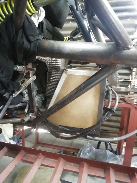
Then, the MK2 fuel tank is not going to fit the newest alterations.. so we'll need an mk3. Made a model this time because I want it the 3rd time
to be the charm.

A whole day of making a removable tray later...

Even with the hear shield, the exhaust wrap I feel it's to close for comfort. So a few versions later we have 42l of fuel capacity and 20mm of
clearance between the heat shield and tank. For that little extra something I have some space age non conductive stick-on pads, just for the closest
bits.
Currently debating which water tank to use from my years and years of collecting, along with where to put it.
This debate also includes whether or not to use the OEM airbox and how in conjunction with the air scoop.
Ariel has an interesting way of doing it... but it means a lot of fabricating an loss of plenum.

had the gf over (believe it or not) and decided to do something nice together, my man logic went: she enjoys sewing =so cloth = carbon is woven = it
must be a cloth = QED she will enjoy some lay-up...
...God, was I wrong
But it turned out nice ! And the Dash got an outing after years in the box.

And the last job today was to fabricate harness mounts and fit them

|
|
|
scudderfish
|
| posted on 21/5/19 at 05:28 PM |

|
|
Keep the posts & pictures coming 
|
|
|
drt
|
| posted on 26/5/19 at 10:43 PM |

|
|
Thanks scudderfish, means a lot to have some encouragement!
This week,
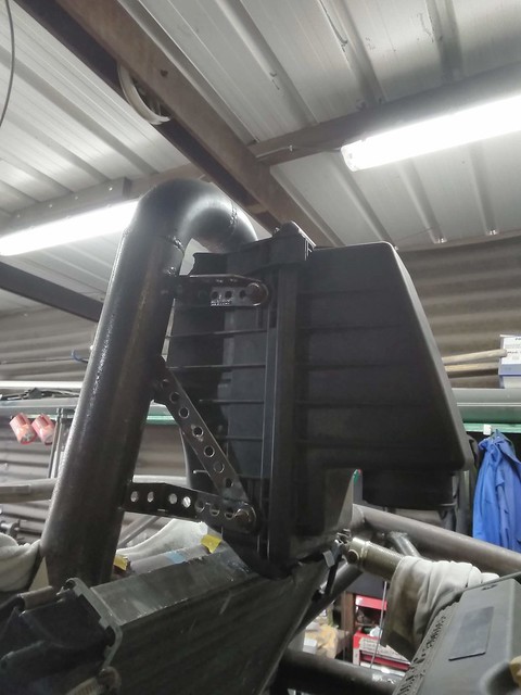
I started with the airbox... this is the OEM rover airbox

Hack sawed it to bits...

So it fits here... so I'm going to use the air scoop (CFRP) just as a cover. A bit disappointing as I was hoping for E46 m3 CSL resonance
noises, but that probabaly would have been a cacophony. This way I can use the OEM paper air filter, which is cheap, cheerful and better than a
chinesium pod filter

So it's a bit of a bodge right now but I'll have to plastic weld or glue some bits too it... and the water drain

After a whole day of fitting, bending, grinding, drilling
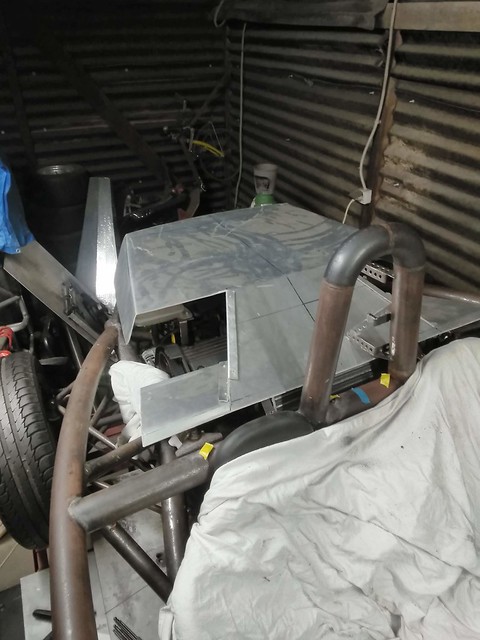
Then, the water tank had to be placed at a point higher then the head/rad/... somewhere where it wouldn't intervene with the air flow coming
from the rad and somewhere where I could block the acces to the cap (100% sure otherwise someone would nick it for giggles)

A few attempts and generations of brackets later...

The end is nigh

So I found a solution to my clutch line problem, this is some thermoplastic hydraulic line... it should be able to cope with DOT4 and my only worry is
that it is only rated for 20bar of pressure. The up side is that by heating the line and the fitting I could just push it on.
But It came to me that the slave doesnt have a bleed nipple ????!!!! How do they do that ????  

Now for the air intake, cut out the space onder the roll bar in alli and then hand bend some strip into the right shape
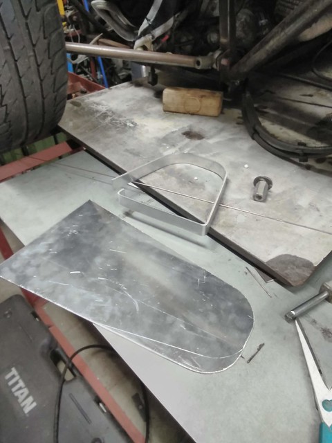
Welded

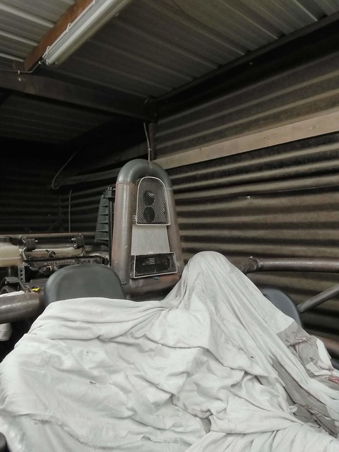
Did the same for a lower intake (not to block the rad) and cut some holes.
The mesh is what I had around, probably going to change it for a better pattern.
And I still have to decide if I'll glue this to the air box or screw it to the hoop.
|
|
|
drt
|
| posted on 30/5/19 at 11:54 PM |

|
|
Update... I'll be looking for opinions on the fuel tank later in this post, so please, fingers on the buttons.
Starting where we left of. The airbox.
It needed a bit more hacksawing.

So now the front is more flat it received a nice multiple bent piece of alli. Glued and riveted, with the glue sealing off the OEM airbox.

Fitted to copy the hole and measure the width of the gap


So a nice hole in the box.

Then some double sided tape and 5mm PVC foam
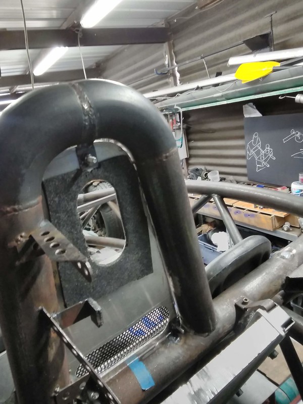
Voila, painted and done

Then, the cooling system.
The K-series asks for some hot water from the engine to always be circulating round bypassing the rad so the thermostat would open.
Not the best design, but it needs this to work.
So had to make a conduit for this, and block off the return from the heater.

I tried for a whole day to nicely bend up the conduit by heating it and filling it with sand.
Needles to say I wasn't successful. For the time being it's going to be 90degree bends then. A bit of a sin... I know 

So here it is with the water tank fitted up too

Then, the fuel tank.

So, here are my baffles. I want your opinions on the design of these. I wanted the fuel to level out between the 3 chambers quickly while refuelling
while still combating sloshing and then have only minor openings to try and keep the fuel near the pick up point.
Around the pick up there is an extra wall so fuel can come into that area relatively easy but won't leave.

It moved a bit under welding...
The baffles are quite clear now, note that I sunk the filler neck 1cm into the tank so the fuel can expand over a 20 degree delta T (I see this as a
worst case)

And there she is (not yet permanently welded) , I forgot to take a picture of the pick up points, I'll do that tomorrow.
Meanwhile, do people use the nylon sifter from the OEM fuel pump units at the end of the pick ups ? Or just leave it open ?
I'm asking because you can't use a fuel filter before the pump I've heard.

The another request: Where can I obtain 70mm I/D hose that is flexible enough to connect the throttle body to the airbox ? (and doesn't collapse
under 0 bar).

Latest job was creating the fuel pump bracket and finding a place for it.
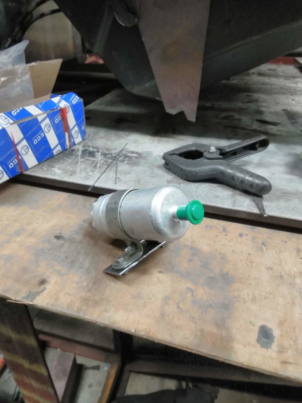
|
|
|
drt
|
| posted on 1/6/19 at 11:35 PM |

|
|
on tonight's special...
Crushing disappointing as no-one gave his 2 cents...
And more bodging
Without feedback I ploughed on, so this is the baffled tank with:
*A return in the foreground
*A pick up (without mesh, cause I was nervous that over time it might come undone) near the apex of the triangular slush guard
*A tube for the idiot light (reserve indicator) thermistor
*Filler neck (far away)
*Breather (near filler neck)
Welded on top and bottom to fight vibrations

Welding side plates
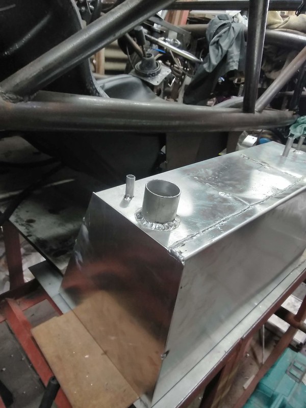
Welded up and pressure testing to 2 atmospheres,
man, alli is really a first time right process. Cause to fix a pinhole just welding over it didn't fix it for me... So grinding it back,
cleaning and re-weld 2-3 cm

So a whole day and night filled up and pressurised later.. no leaks

Double sided tape and foam


Bending the straps
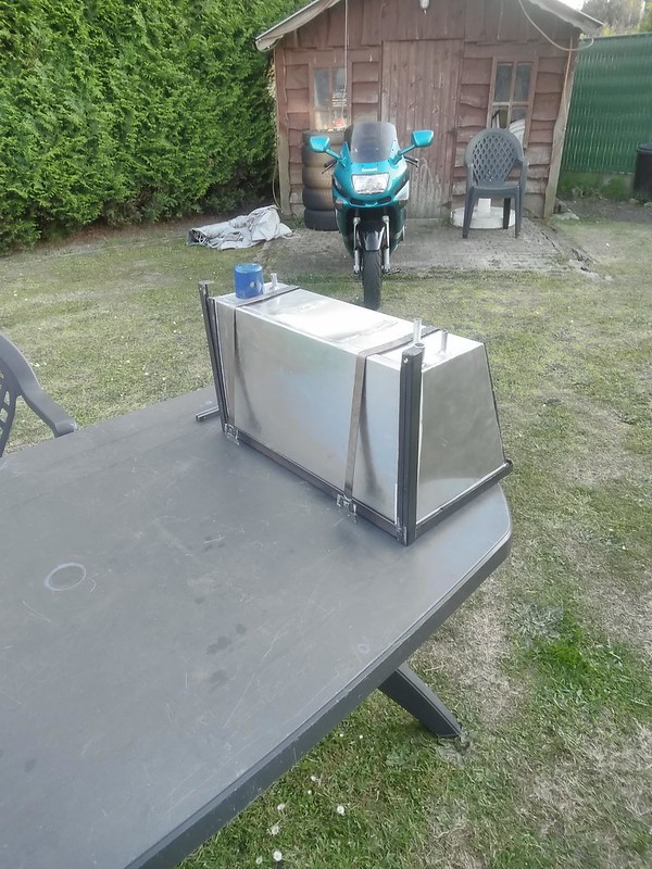
1mm steel work

Foam backed, studs welded and done up

|
|
|
perksy
|
| posted on 2/6/19 at 09:27 AM |

|
|
Enjoying reading this and the photos are a good size now as it makes it all easier to read and see what you are doing 
|
|
|
miskit
|
| posted on 3/6/19 at 03:16 PM |

|
|
Looks amazing - thanks for taking the time to write upm - like the photos much better.
Also don't worry if people don't always chime in - they are still reading and enjoying! 
|
|
|
dan8400
|
| posted on 4/6/19 at 06:23 PM |

|
|
This is really coming together now. Some lovely fabrication work.
Well done. Keep it up
Thanks
Dan
Hey - That's Journey!!!
|
|
|
drt
|
| posted on 4/6/19 at 10:36 PM |

|
|
Thanks for the kind words,
I welcome any comments you guys would have. Since I am not afraid of redoing something and together we know more then apart.
Especially on this forum where the knowledge base is staggering :p
This time... something what every se7en owner will envy...
A nice roomy box...
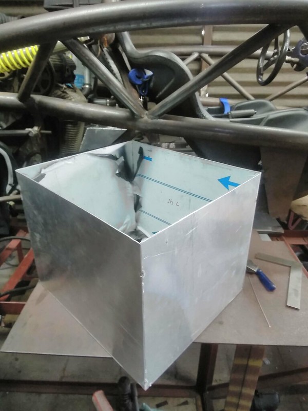
That needs a tight squeeze...

Think I'll call it a boot, mind also the members that where added at the front to stiffen up the protrusion near the box.
Seriously, I measured the frequency off the battery tray/nosecone bracket structure and found that it wasn't stiff enough.
well, now it is

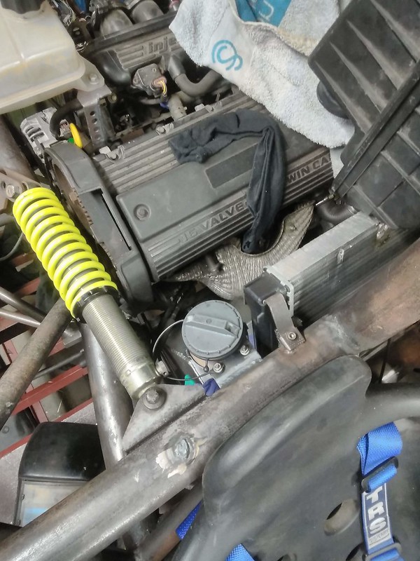
Then I had to find a place for the gas cap (rover filler neck)... since it's not lockable it had to live under the -locked- bonnet.
I prefer it on the right side as that is the curb side over here.
For the ignition I'm using the Rover barrel (with the steering lock bit hacked off) since it's more decent than the aftermarket ones and
it fits the RFID receiver unit. Most barrels dislike water and the RFID doesn't for sure. Meaning that if the barrel had to be in reach when
fully strapped in there weren't many locations suitable. Also the key fob had to be out of reach of my knees to avoid me getting aggravated.
Conclusion was to put it under the knee-shelf thingy but in the middle.
So starting off, like usual, with a perfectly good bit of metal... to then grind and drill it to oblivion.

And there you go, you might think it's a big lump of unnecessary weight to just hold the barrel. You'd be right but I'm planning of
attaching the relays, breakers etc there too, making use of that bit of structure.
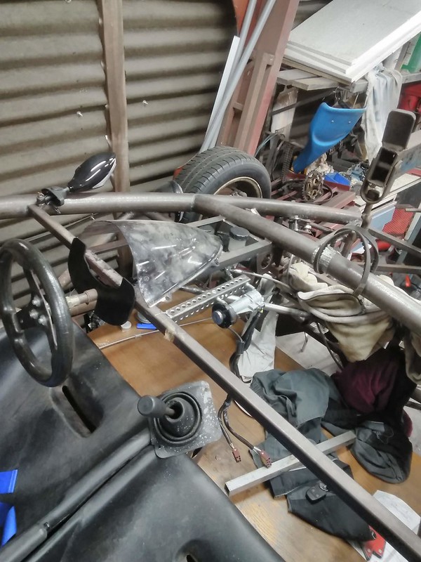
So to allow for the new rad position the mold for the bonnet needed to be altered.
I chose to just lengthen the lip 60mm as this would make the front sit higher and the back end move backwards a bit... aesthetically it's better
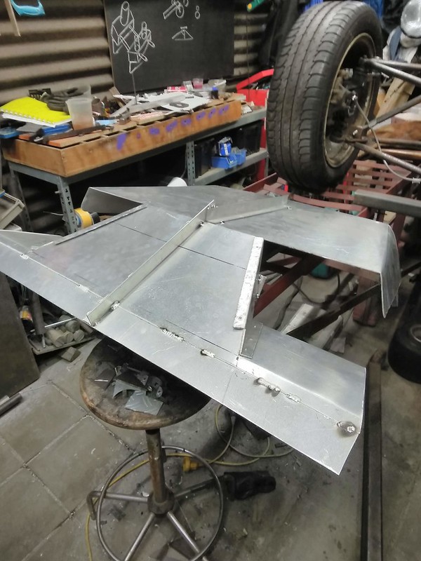
(I was surprised too). That lip would have cut outs in the CFRP item to allow air to flow into the rad.

After days of alli welding I was finally getting proficient again, so decided to add the stiffeners to the mold as it has been on the to-do list for a
long time but as the sheet is thin and alli has a penchant to warp it daunted me for the longest time.
Lastly I started making weld-on-cable-tie-anchor-points for the rooting of cables.

A real labour of patience ...

|
|
|
Theshed
|
| posted on 5/6/19 at 09:27 AM |

|
|
A slightly easier solution to cable ties is to bond on these things - that is what is used in many race cars
https://www.newark.com/thomas-betts/tc-105/cable-tie-mtg-base-aluminum-25/dp/12C2341
|
|
|
drt
|
| posted on 5/6/19 at 11:15 AM |

|
|
You beauty!
Promptly ordered
|
|
|
drt
|
| posted on 11/6/19 at 03:55 PM |

|
|
Not a lot this week
some captive nut plates for the cfrp underbody.
MIGed these as with the TIG I am to prone to melting the threads.
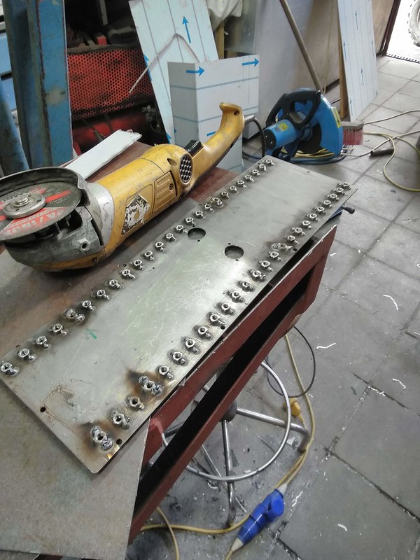
Cut and debured

Tried to fit these nut plates by using the mold... I wasn't successful, so I'll have to invent something when the product is made.

In the mean time... I had a hover car
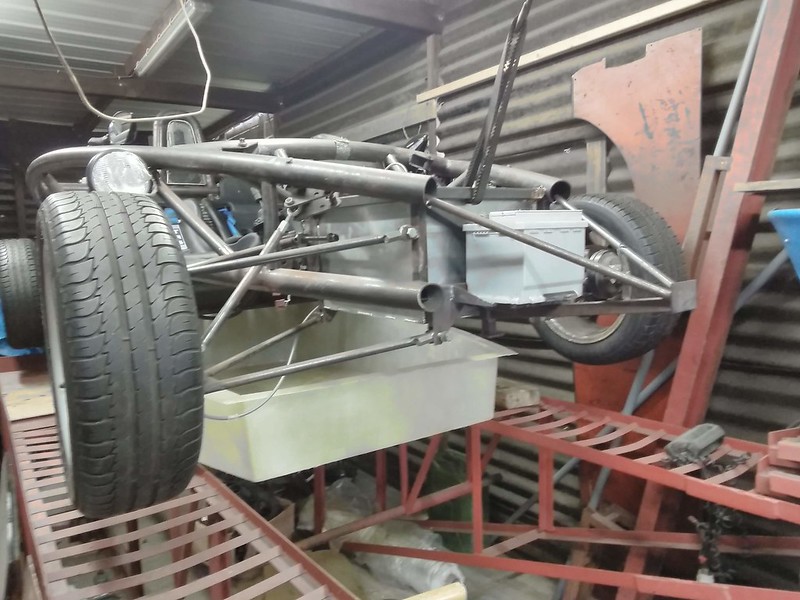
Most of my friggen time went to electrics, buying fuel and some coolant lines/
I must say the RAVE CD's are less then helpfull
and for some reason all the pinouts I can find are not relevant to mine
I'm posting it as a separate question in 'electrics'... I'm very happy for any help
|
|
|
drt
|
| posted on 26/6/19 at 05:37 PM |

|
|
It has been a while, srr.
Lots on the plate.
Some interviews on the horizon and now doing a interim job just to fund this XD
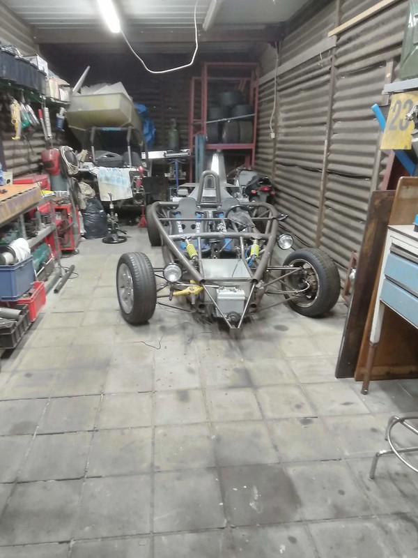
So since last time... I put her on her wheels and cleaned the hell out of the shed
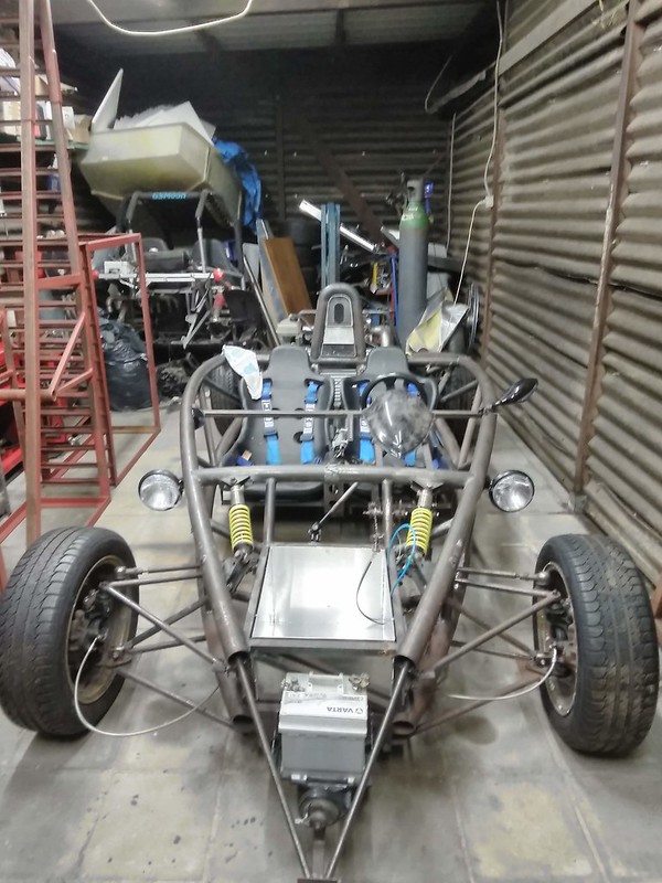
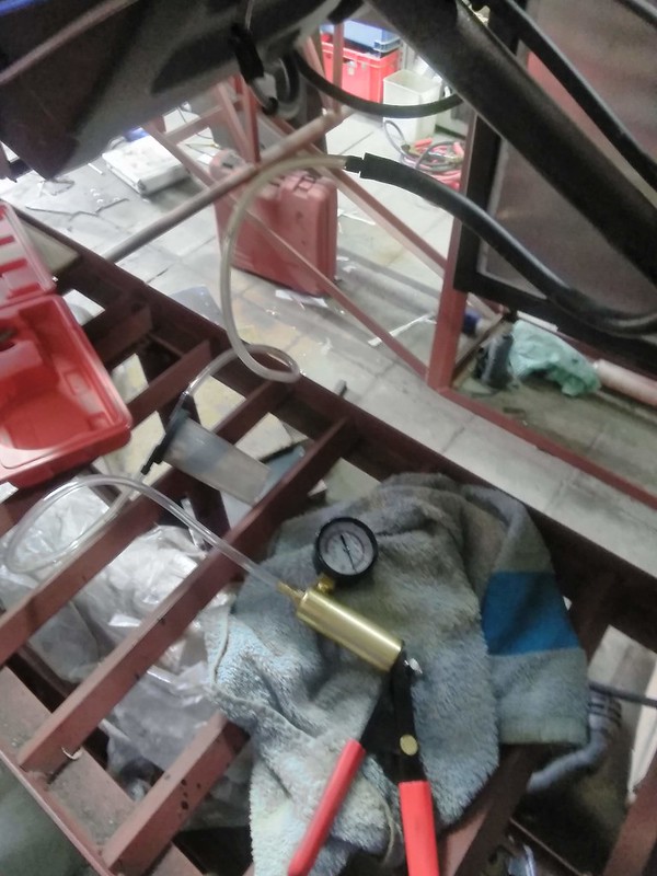
Since the electrics where being tried out preliminary, I wanted to start it.
To not let the pump turn dry I used the brake bleeder to get petrol in the system.
Good news, the whole system works and doesn't leak.
So, the observant might have spotted that I was using the lights at a 90 degree angle...I tried rotating the mirrors for it to comply... no dice.
Therefor experimenting with a new position, where I planned the indicators
Air intake... needed some ''gasket''

Like this

And then a bit of a bodge. Turns out this material can take a partial vacuum, is bendy, cheap and easy to get hold of XD

And then the first wave of new bolts

|
|
|
drt
|
| posted on 19/4/20 at 10:47 PM |

|
|
The show must go on...
Since the last upload, a novel-grade series of events has taken place.
the gist of it ?
Father had found a way to leverage all of his outstanding debts with the property.
After a fire-sale of most of my tools I just managed to outrun the bailiffs.
To my great dismay, the hangar I spent so long building, lathe and ... is all gone
What follows are some pictures of the last jobs done before things went south... and how things are likely to go on

When I left you last time, lights were the last order of the day. these will be the stays for the headlights and indicators in their new position.
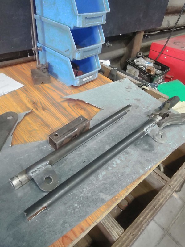
with the indicators screwing straight in and the lights on the small plates. Power runs internally

After faffing around with the position this is what I decided upon.

Then, to get around using the Rover master and clutch slave (that can't be bled etc) I decided to use Miata parts... as they are easily
attainable, small, have the correct displacement and parts supply will be around for years to come.

I shall take some pics of the paddle box alterations, but this is the bracket that will bolt to the gearbox.
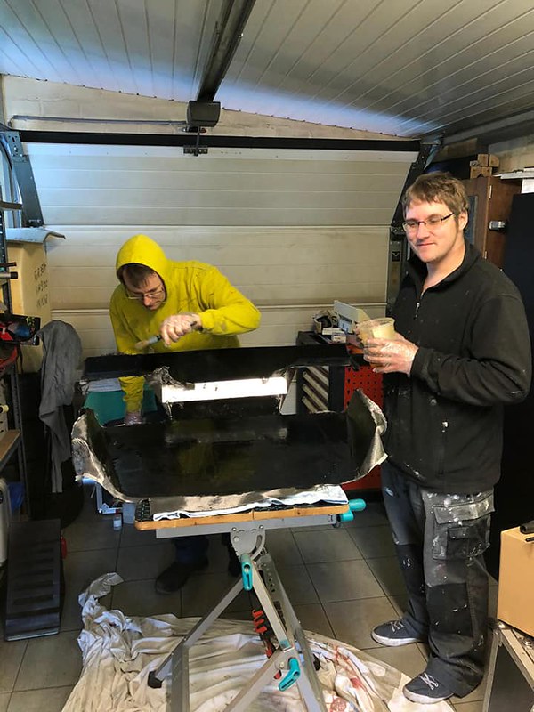
The engine cover being layed-up in its mould.
 [ [
Nice wetting so far

Now sticking on some ribs to overlay with cloth to increase stiffness.
Note the gap for the air scoop.
Still not sure if to keep the air scoop separate or to incorporate into the cover.

And then the great escape...
Good to know that the DIY trailer works.
Quite comical that tow vehicle of mine.
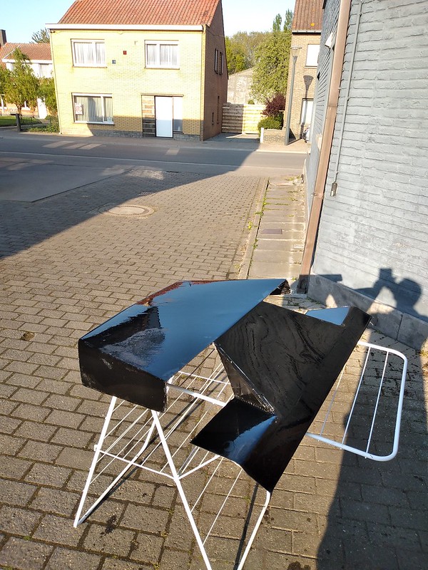
And this morning I got round to demould the engine cover.
Not to shabby.
So my new situation calls for doing stuff on the road side on a drying horse.
Ghetto style, I think this is referred to.
In the future I still need to do some laminating and electrics and various small bits... I'll find a way
|
|
|
drt
|
| posted on 1/5/20 at 08:45 PM |

|
|
on to the air scoop
Got some real release wax in stead of the one I was using

Than, using some paper to get a pattern to cut out the cloth
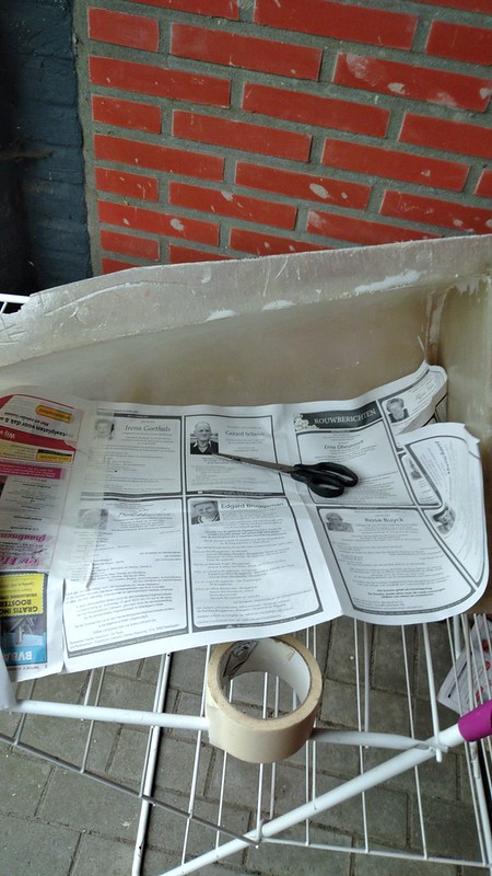
3 coats of wax,
2 coats PVA
few layers of cloth
some resin
a day of drying time
half hour of prying it out
voila...

After getting the PVA off

Still needs some surface finishing,
but it does fit.

|
|
|
jps
|
| posted on 1/5/20 at 10:05 PM |

|
|
Sory to hear of your change in situation. Your work continues to be impressive!
|
|
|
drt
|
| posted on 1/5/20 at 10:23 PM |

|
|
Thanks JPS,
I'll try to keep it coming!
|
|
|
drt
|
| posted on 26/5/20 at 12:41 AM |

|
|
This time
I've been making a board with the 5AS, ECU and switchgear to plug into the engine and get it running

Been cutting fabric and cork filling to start making the biggest part of all

Coworker was so generous to lend me a hand laying it all up
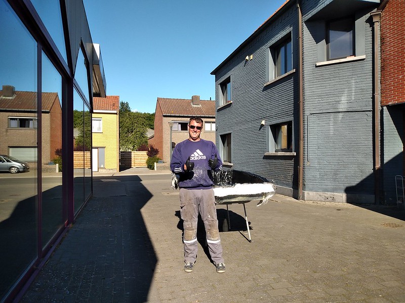
Lots of swearing, scrathing and beers later

|
|
|
wylliezx9r
|
| posted on 26/5/20 at 08:05 AM |

|
|
Great work. I hope your financial circumstances improve.
I spent a lot of money on booze, birds and fast cars. The rest I just squandered.
George Best
|
|
|
drt
|
| posted on 17/6/20 at 05:55 PM |

|
|
Thanks,
another update,
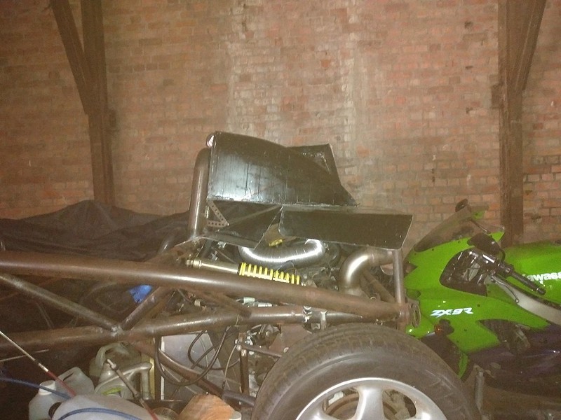
So now we have the scoop and the bonnet occupying the same space.
At first I was going to keep them separate like a real Atom. But the whole assembly will be stiffer and lighter if I marry them.
That's because in the real Atom the scoop functions as the airbox too.

Some 'carefulling', measuring and cutting later

Making a hole for the airbox
all of this was quite heartbreaking and nail biting... one wrong cut and it would be back to laminating.

Now they are married through the force invested in them by Epoxy, waiting for some cloth to be applied internally.
They're is a little anomaly, but I'll wait till someone spots it before trying to give an explanation
|
|
|


