
Just Imported a Megasquirt MS2V3
big-vee-twin - 15/10/11 at 07:56 AM
Morning all, just imported a Megasquirt kit from DIYAutotune, going to start soldering up this afternoon. Initially I was going to buy an assembled
kit but as I used to work as an electrician repairing control panels soldering 6 hours out of every 8 every day for 8 years (20 years ago) I would
revive the old skills and have ago at putting one together.
This is what arrived, I will keep taking some photographs through the assembly to keep a diary and report back how hard difficult it is if, anyone is
interested?
[img]

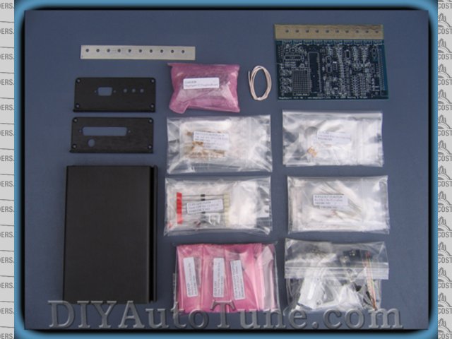
Megasquirt Kit
[/img]
Oh, I forgot to mention they are running a promotion to offer 12% discount, but to get this they want to drive up their 'Likes' on Facebook
to 6000, so have a look on their page and press like and in no time the discount will be available for those who are planning a purchase.
[Edited on 15/10/11 by big-vee-twin]
monck - 15/10/11 at 08:29 AM
i would be intrested to hear how difficult it is as i was thiking of a kit also
Good luck
Ryan
lotusmadandy - 15/10/11 at 08:51 AM
I bought one of the v3 self assembly kits.
Tbh it was a doddle to put together,i just
prined off the build manual and followed it
to the letter.It helps if you have a stim
for testing as well.You will also need a fine
tip in your soldering iron.
Andy
Snuggs - 15/10/11 at 08:57 AM
Most of the soldering is straight forward however there are a few small transistors that the pads are extremely close together and it is easy
to get a solder bridge.
Do ALL the tests that are in the assembly instructions when you are told to do them.
Take your time and you should be OK.
RK - 15/10/11 at 03:21 PM
I had a bad ECU, decided to change it, thought about this, realised I couldn't solder that well (and I've done HUNDREDS of wires in my car),
there weren't a lot in engines like mine (CA18DET) and bought an AEM for about 5 or 6 times the price. I want to see this work, so keep us
informed would you?
BTW, I bought another small kit at the electronics store, for practice, which I tried to make work, but couldn't. My car wires are solid however
(they all passed the pull test), but obviously larger, leaving a lot of room for error.
big-vee-twin - 15/10/11 at 04:05 PM
Ok, here's the fruits of my Labour today- built the stimulator.
You put it together in no particular order just put the numbered components in the numbered holes -bit like painting by numbers really.
The transistor pads are very close together as previously said but managed to get them done with a little patience, everything else was very easy.
I had treated myself to a new soldering station with anti static connection. I connected this to an anti static soldering mat and connected myself to
it by a wristband. Here's a pic took about three hours to do.
If you notice I haven't connected one of the resistor legs yet-I'm going to use this LED which is designed for the Idle valve, which I
haven't got, to monitor a second coil output as I am planning to mod the MS to waisted spark without using EDIS
[img]

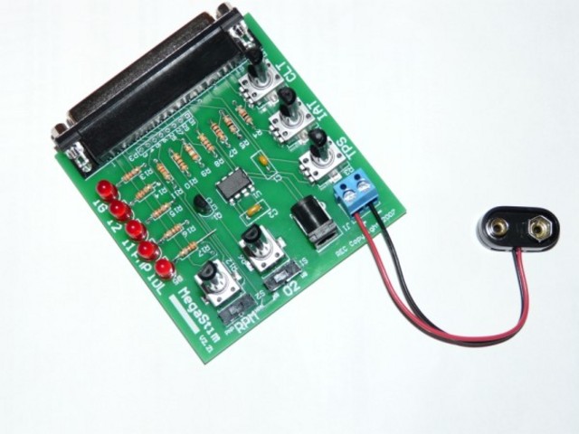
MS Stimulator built
[/img]
big-vee-twin - 16/10/11 at 05:08 PM
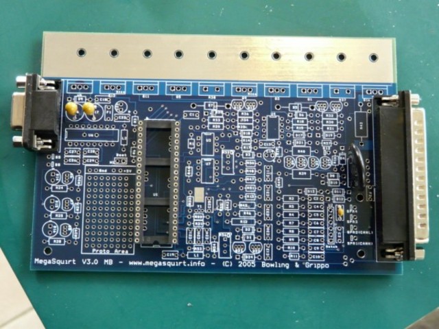
Here's some more progress pics, the stage 1 build of the 5 Volt regulator is now complete and tested out ok.

[img]
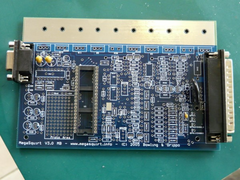
Stage 1 MS build
[/img]
[img]
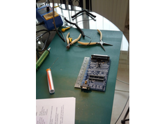
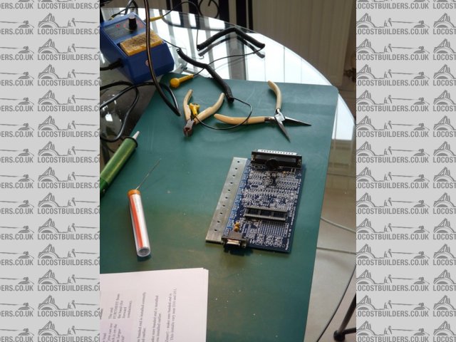
Kitchen table
[/img]
[img]

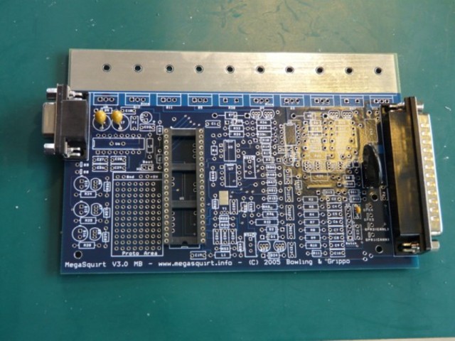
Megasquirt build stage 1
[/img]
All very straightforward so far, just following the instructions and using the layout diagram to locate component positions.


