3 ,4 or 5 linked Live Axle
Antnicuk - 11/12/08 at 06:39 PM
I have been thinking about my rear end, which is worrying!
Following on from my ARB on a live axle thread some things have been pointed out about my set up.
It seems the stylus is one of few cars to run the rear upper arms from the rear (unless someone knows different)
Most 4/5 linked live axles run both trailing arms from in front of the axle. I assume there is a reason for this. its better?
With 2 upper arms coming from the rear and 2 from in front, the axle moves up and down in a nice vertical movement and doesnt arc forwards towards
the 12oclock position like the other method...... but,
when going around a corner and the suspension moves 3-4 inches up on the outside wheel the arms are getting shorter and trying to lift the nose of the
diff, which isnt a problem but the otherside that hasnt rasied has kept the arms the same length and is trying to prevent the axle twisting and
lifting the diff nose. SO...... there is a lot of stress on the arms during heavy cornering.
I would imagine that this isnt a problem on a road car but on a track car the different forces on the axle must be tremendous.
I am considering relocating my upper arms to a point forward of the chassis! Has anyone else tried this?
Where are they mounted on the fisher models that the stylus is derived from?
Having had a quick look tonight it would be difficult to mount them above the lower arms, as the fibreglass is in the was and also the springs, but
what about using a single upper arm in the middle locating in the gearbox tunnel. There is a racing series that runs a 3 linked system.
I think there would be enough room to clear everything even with my rather large diff.
Any thoughts??
Volvorsport - 11/12/08 at 06:51 PM
caterhams have an A frame at the bottom and two forward facing arms with the de dion setup .
youll need to find a structural place to attach them to , if fitting the forward pointing arms otherwise the mounts will just flex and/or introduce an
unwanted force into teh chassis .
my favourite wouold be the transmission tunnel.
mark chandler - 11/12/08 at 07:06 PM
Coil sprung range rovers run an 'A' frame to the top, trailing arms at the bottom, If I was going to redesign something I would definately
look at this solution.
Effectively cortina's had the same arrangement but the point of the 'A' frame never met. As its triangular you can then lose the
panhard rod as location is now controlled from the centre.
Not sure what SD1 rovers used, Watts linkage and trailing arms so may be worth a google.
Antnicuk - 11/12/08 at 07:07 PM
when you say an A frame, is that 2 points mounted to the chassis and one in the middle of the diff?
I have a tube frame around the prop at the entrance to the tunnel which would be where i would look to mount the arm.
mark chandler - 11/12/08 at 07:25 PM
That's the one, then a big ball joint on the axle.
britishtrident - 11/12/08 at 08:12 PM
The setup on your car is a well established method of location frequently used on De Dion axles (for example 1960s Rover P6 2000) and has also been
used on some cars with live axles most notable the Lotus Seven Series IV.
The reason why it is used is that reduces roll steer to a minimum. As with the 4 trailing link layout used on the book Locost it should be set up so
as the links are horziontal at normal working ride height. However with the leading trailing link setup as on you car is not often used because it
can cause extreme loads on the chassis mountings and axle under roll if the roll centre is not located correctly.
For the same reason the system is highly dependant on having some compliance designed into the system to absorb the conflict of arc, with a live rear
axle the only way to do this is to use rubber bushes.
It has one other major downside when used with a live axle in that because the axle rotates the angle of the rear propshaft joint changes uqually to
that joint at the gearbox end. For these reasons the suspension travel range must be kept short.
If you want to change the method of axle location the A frame (or converging links -- really same thing) above the axle centre line as on the Cortina
Mk3 to 5 is a non starter. This type of linkage would was raise the the roll centre much too high for a sports car --- high roll centres should be
restricted to very softly sprung vehicles with high CG height such as the Range Rover.
Unless you have room to either copy the full book Locost/Westfield suspension layout or the Lotus/Caterham Seven S3 (a frame below the axle) your
only option might be an IRS conversion
Rover P6 De Dion rear end note joint in middle of the De Dion tube as well as being a sliding joint allows some twist .
[Edited on 11/12/08 by britishtrident]


Rescued attachment p6dedion.gif
Antnicuk - 11/12/08 at 08:29 PM
my brain hurts 
Can some explain Roll Steer and is it different to roll centre?
is this set up different to the one you are saying wont work?
http://www.lateral-dynamics.com/products/source/_3link_iso_view.jpg
Canada EH! - 11/12/08 at 09:12 PM
Roll steer, as it says, with body roll the trailing arms on one side lower, thus shortening the distance to the pickup point. So in a tight left turn
the left rear wheel moves forward in the wheel well from it's normal position, helping the car to turn left. If you ever get to see a race with
World of Outlaws Modified cars on dirt it's plain to see.
MikeRJ - 11/12/08 at 09:21 PM
The setup used on your Stylus is also shared with the Striker, widely acknowledged to be one of the finest handling 7's this side of a Caterham.
As long as compliant bushes are used in the locating arms, the stress on the mounting brackets is minimised. This setup absolutely will not work with
rod ends however, the roll stiffness would be huge and something would break very quickly, and for the same reason polyurethane bushes are not a great
idea. It is worth checking the axle mountings occasionally however, cracking is not unheard of.
Roll steer is what you get if the axle does not remain located at 90 degrees to the axis of the car under roll conditions, i.e. one wheel moves
forward, the other moves back so you get a steering effect.
A roll center is simply an imaginary point about which the cars will pivot under roll conditions. They don't tend to remain fixed, throughout
the suspensions movement.
Antnicuk - 11/12/08 at 09:31 PM
thanks very much for the info.
The existing arms are poly bushed but seem to be ok.....
its strange how some say its a crap system and others say its good?
So what about the 3rd link system in the middle at the top and retaining the pan hard rod?
Antnicuk - 11/12/08 at 09:59 PM
so i shouldnt use rose joints (even at one end  ) on my trailing arms but i want to make them adjustable, slightly, what are my alternatives?
I have seen insitu adjusters but they look a little weedy.
Welding isnt a problem but i need to find some threaded tube thats long enough to get a decent amount of thread in to keep the arm strong. The
threaded inserts that are sold with rose joints are only an inch long which isnt long enough to have any adjustment.
I dont even need to be able to adjust it in situ, if i have to remove the bush from the axle or chassis to adjust its fine as i want to do it once!
Any ideas?
[Edited on 11-12-08 by Antnicuk]
MikeRJ - 18/12/08 at 05:07 PM
quote:
Originally posted by Antnicuk
so i shouldnt use rose joints (even at one end  ) on my trailing arms but i want to make them adjustable, slightly, what are my alternatives?
Sorry for late reply, only just seen this! Firstly why do you need the arms to be adjustable, is the axle not correctly angled at the moment?
I wouldn't personally put rose joints even at one end, the more compliance you remove from this system the greater the stress on the mounting
brackets. When I got my Striker I wasn't very happy with this system, it seems wrong to me to design a system that deliberately binds up to
provide roll stiffness. However, you simply can't argue with the results it has achieved on the track.
quote:
The threaded inserts that are sold with rose joints are only an inch long which isnt long enough to have any adjustment.
The inserts are welded into the ends of hollow tubes, so the male thread can be as long as you like within reason.
Antnicuk - 19/12/08 at 06:42 PM
i did a 4 wheel alignment and the rear axle is slightly toe in on 1 wheel and out on the other. Plus i want to move my axle back about 10mm to centre
the wheel in the arch so i thought i could hit a few birds with one stone.
Surely a rose joint gives much more movement than a nylon bush??
MikeRJ - 19/12/08 at 07:27 PM
quote:
Originally posted by Antnicuk
Surely a rose joint gives much more movement than a nylon bush??
It allows more angular movement, but permits virtually no longitudinal motion (i.e. forces pushing and pulling on the threaded part) which is what
causes the problem with this suspension layout.
Think of it this way, when the cars rolls the links at one side of the car are trying to rotate the axle in one direction but the links at the other
side are opposing this. If there is no compliance in the system (i.e. flexible bushes in the links), the only way the car can roll is if something
starts bending (axle brackets in this case). Repetitive bending of parts not designed to bend will rapidly cause fatigue failures.
If you need to increase roll stiffness then removing the compliant parts of this system is not the way to proceed, an anti-roll bar would be an
appropriate solution.
If the axle misalignment is only small, then consider elongating the mounting holes in the axle brackets and putting the system together with a couple
of repair washers over the slotted holes. Once aligned, the washers can be welded to the brackets to form a permanent correction.
Antnicuk - 30/12/08 at 06:23 PM
Time for an update,
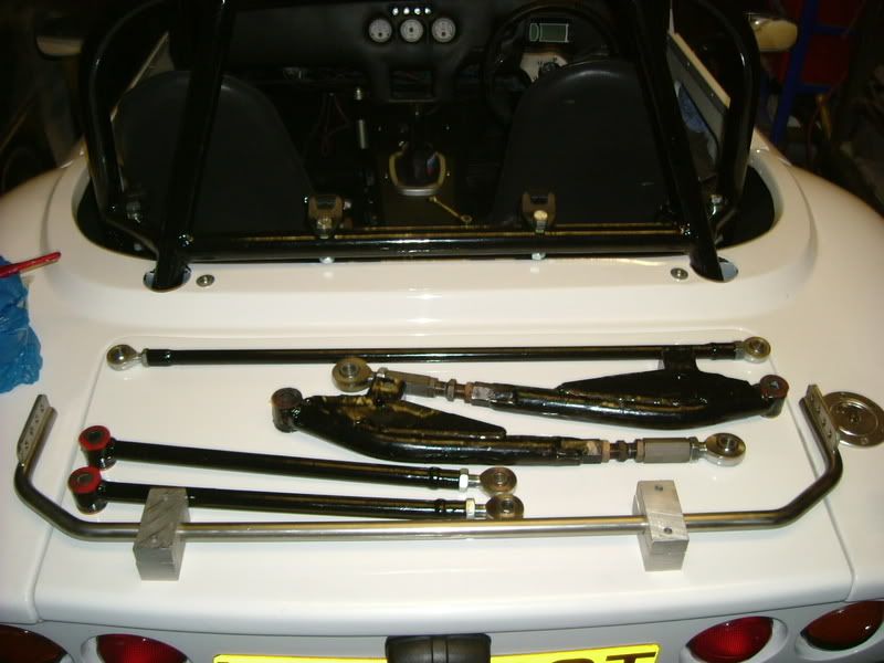
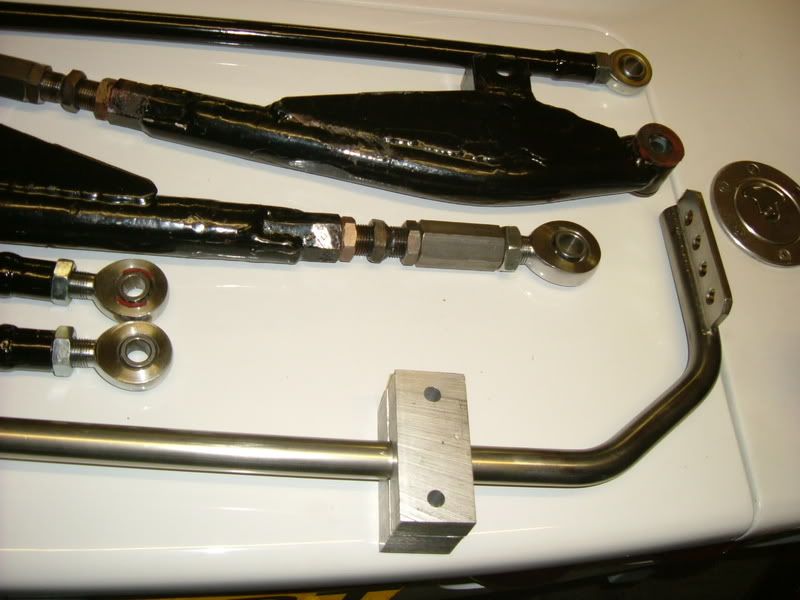
I have decided what i'm going to do, I'm keeping the original configuration for the rear suspension arms and fitting rose joints to the
chassis end with insitu adjusters on the lower arms.
I have also put left and right hand threaded rose joints on the p/hard rod for ease of adjustment.
I made a new anti roll bar for the front, I made it out of 19mm solid stainless and its the same shape as the stock one so easy to change, if its
too stiff its easy to make another out of either tube or smaller diameter bar.
Once these are fitted i will strip the front down and rose joint the w/bone ends. I ordered the rod ends yesterday.
Off topic!
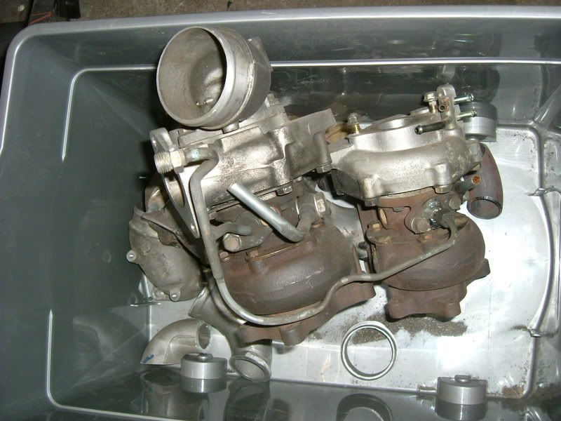
The box of goodies is a pair of turbos. They are originally fitted to a Mazda Cosmo which is a 3 rotor twin turbo (sequential) car that mazda didnt
import to the UK or the US, it looks like a Toyota Soarer. I have seperated them and will run them in parallel on my engine instead of sequentially,
this should give me quick spool and continue to flow plenty of boost way beyond 8k rpm. We had these knocking around the workshop as my cousin
fitted a 3 rotor engine in his RX7 and fitted a huge single turbo so these were going spare..... worth a try as my stock turbo is way too small and
runs out puff


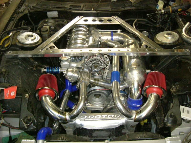
Here is a piccy of the 3 rotor in the rx7 (Bling), this was with a supercharger fitted but we changed it and its now turbo'd


[Edited on 30-12-08 by Antnicuk]


