
3D printing rear hub carriers
b14wrc - 8/10/20 at 06:44 PM
Hey, so Iím nearly finished my workshop which means I can get back to building the car after not really progressing it the past 4 years. Those that
followed my 20vt thread build will know my rear hubs are butchered Fiat coupe front hubs that I did some fabrication to, was never really happy with
the weight or look of these, it always felt like a bodge. Having owned a series 1 Lotus Elise I am aware of how lotus used extrusions to create the
original cars hubs and wondered if it could be something to look at here. So taking a card board template of my current pick up points, which I am
actually happy with I went about re designing my hubs with the intention to either cast them or have them machined from billet in the future. Probably
will give the sand casting a go just for a laugh anyway as thatís me.... 
So, here are the drawings:
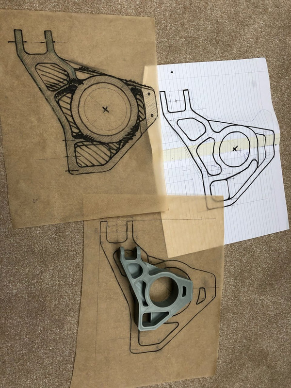
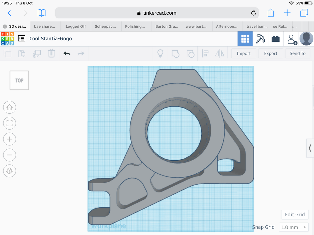
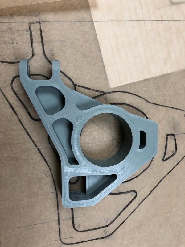
This is a small prototype.
I then modded it to print a final mock up part, this was set off on Sunday and just finished today.  nearly 90 hours on the printer.
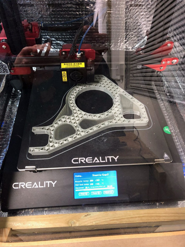
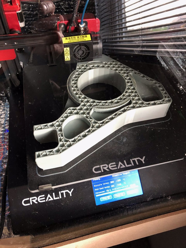
This is the part complete, I am going to drill the fitting holes tomorrow and bolt it on, there will be a part machined for the bearing which will
also space the hub correctly, interesting to see how it all comes together. Bit experimental, but definitely ďlocost styleĒ.
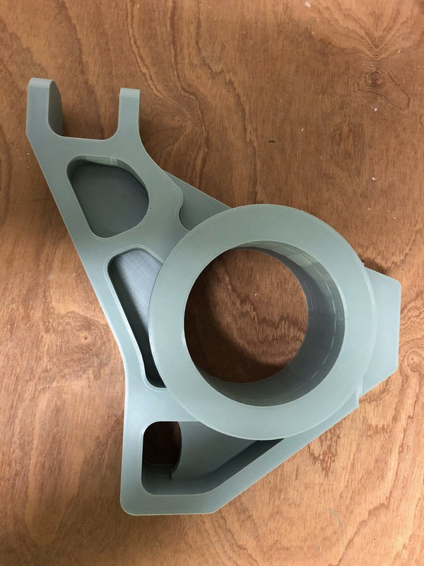
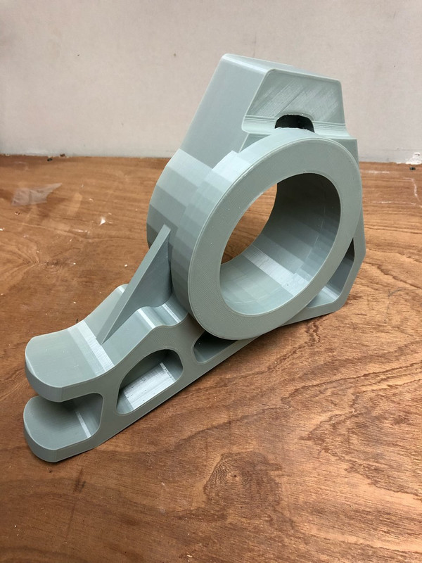
Tomorrow night Iíll get it installed and see whatís next. Planning on making my front rocker arms for my inboard shocks in the same way.
Rob
[Edited on 8/10/20 by b14wrc]
Mr Whippy - 8/10/20 at 10:21 PM
Nice although I think I would have put at least 5mm radius fillets in all the internal edges to reduce stress concentrations, it's just good
practice. Question is how do you know its strong enough?
Badger_McLetcher - 9/10/20 at 08:16 AM
Nice! Concur with Mr Whippy regarding the addition of fillets in the buck. Or add material that can be machined out into a chamfer or fillet,
otherwise those sharp corners will be stress concentrators and magnets for corrosion. If you design it with the correct draft, the 3d printed version
can be used as the pattern for a 2 part sand molding (plus cores) - or if you print it from PLA a "Lost PLA" approach could be used.
I'd be tempted to at least do some hand calcs on it, or FEA if you have access to it, just to highlight weak spots if nothing else.
Home casting is always a bt hit and miss, especially first attempts from what I've seen! Measuring theoretical weight vs actual weight should
tell you whether you have significant inclusions, but it may be worth making one and then cutting it up to examine any issues. The metal can always be
recycled!
Or just get it machined out of billet - there's a reason why aircraft do this for structural components 
Sorry if you know all this, don't want to come across as condescending!
BenB - 9/10/20 at 11:56 AM
I'd be wary of casting anything structural at home. I was thinking of 3d printing throttle trumpets and then casting them. My thoughts had been
to print in ABS, coat in refractory plaster then dissolve out the ABS with acetone or just buy some proper wax filament. Lost PLA seems to work
reasonably but I've seen some issues with it not fully coming out or burning and leaving debris.
Only issue is at present I don't have an ali smelting furnace....
I suppose if it's not possible to add chamfers with the software it would be possible to change the infill density on those parts to 100% using
differential infill and then manually chamfer them? I suspect it would't need a large chamfer to be beneficial.
From the photos it looks like it's a STL file? I know in Freecad I was getting those artefacts on circles until I adjusted the export
settings.
Other than those artefacts it's a nice looking print!!! What filament are you using?
tilly819 - 10/10/20 at 10:55 AM
If you are going to use those as a buck to do a sand casting. Have you included some draft angle to allow you to remove the buck from the mould once
it has been packed. Just asking as the sides look very square in the images.
Also it looks like you have a large undercut that will stop you from removing the buck from the sand. (last image you posted)
Looks like a great project, Hope it all works out. Following with interest. 
[Edited on 10/10/20 by tilly819]
b14wrc - 10/10/20 at 01:41 PM
Hi all, thanks for the comment. This is just a prototype and I agree with the issues pointed out. I use Rhino at work for 3D modelling but drew this
in Auto CAD which I have more 2d drafting skills with so was just keen to get to the printing rather than complete the detail. So banged out the STL
file in an hour from my few days of drawings Iíd done.
From this mornings tinkering in the garage, there are several changes needed. So going to rework these and spend a bit more time in CAD to get the
problems sorted. This is the mock up so far:
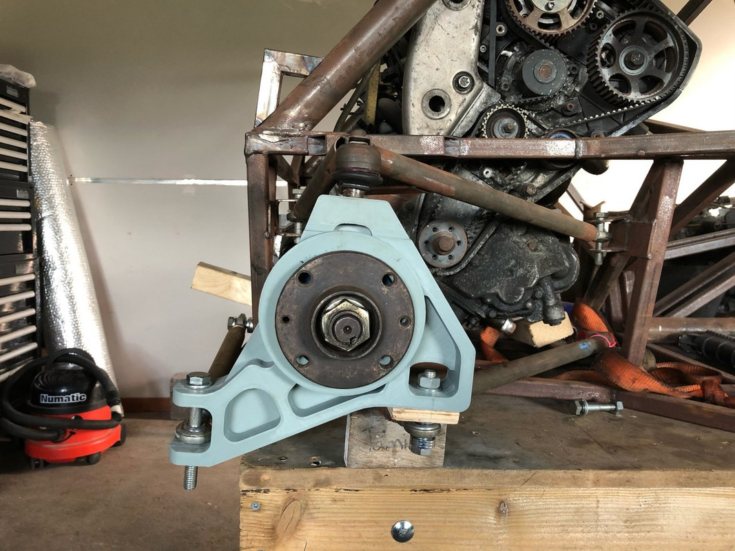
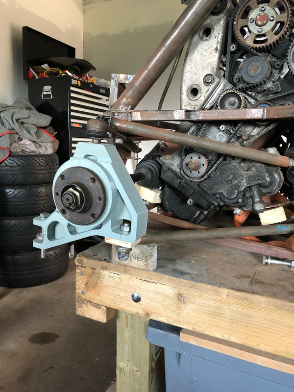 image hosting website
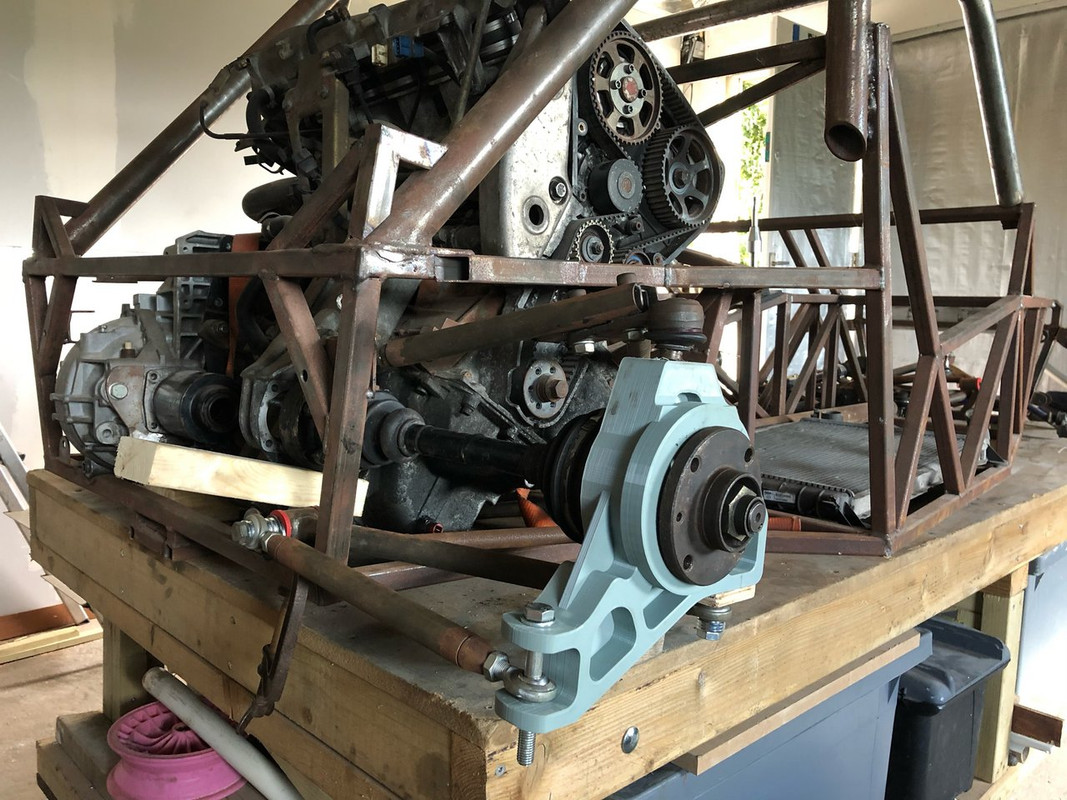
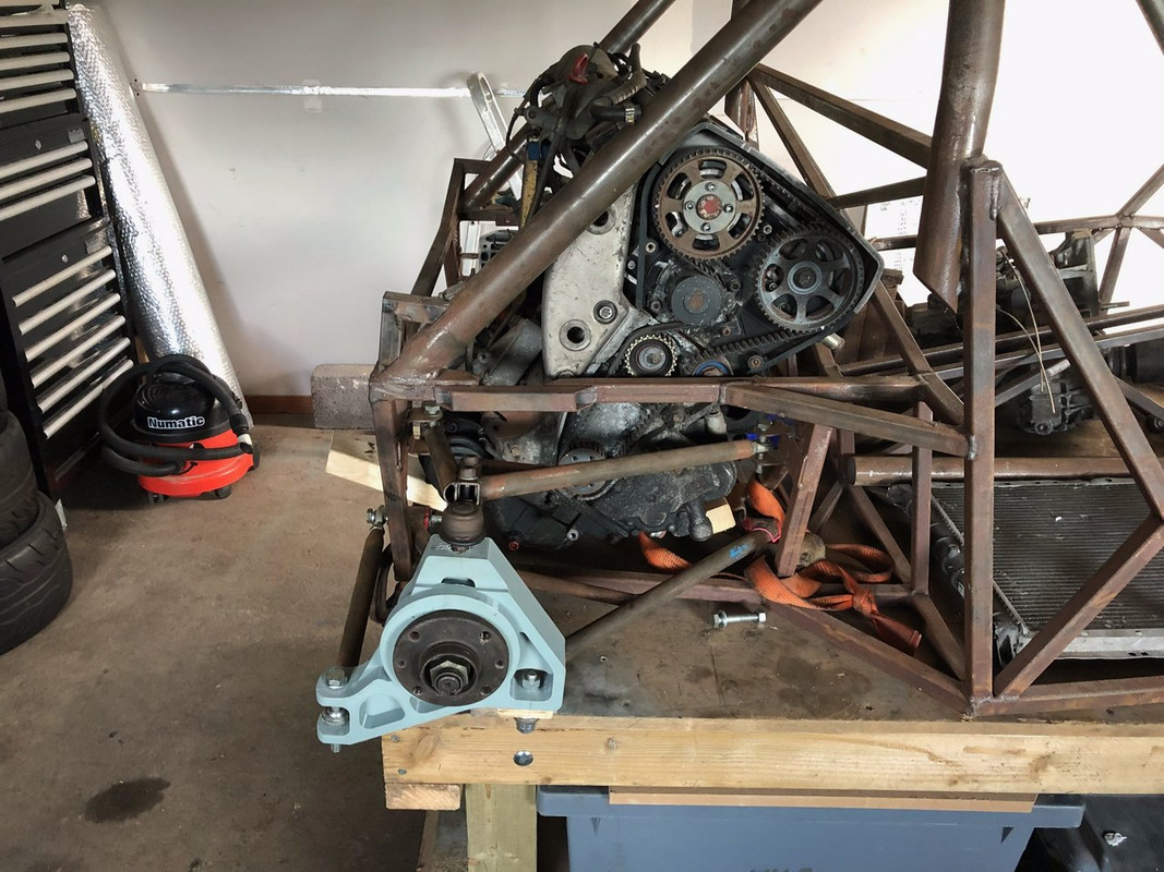
Generally, Iím reasonably happy.
The top wish bone angle is now much greater than I originally had it and the way that ball joint fits is all wrong. Iím thinking of printing the
bearing and work back from there. If I did cast this it be too big to turn on my lathe to machine the bore so thinking of having a bolt in bearing
carrier which bolts to the hub.
I was thinking of going down the road of plaster mould to cast this, I would print in PCL which is a very low temp filament (70-90 deg C) and could be
melted out so release angles and under cuts less an issue.
This was just printed in grey ABS, about 500g cost £5.00. ABS is a pain to print (250 deg C and needs bed heating to at least 100, hence why I built a
cabinet for the printer) so will probably try something else next time to help speed up the process. I may make the next version in parts that join
together, help reduce support waste as there was a bit with this print. Also if I make it modular when doing the sand cast that would help release it.
I could radius the sections with a hot glue gun if I canít figure it out in CAD.
As for the strength, I will do some hand calcs but I have based the geometry on the ďElise partsĒ rear hub design, I would probably build one first
and like suggested do some destructive testing. What will be the weakest link, big block of alloy or my welds on the wishbones..... itís one of those,
with out full structural calculations on everything there is some uncertainty around it all hanging together, but I feel it has a bit of margin in it.
Probably will look to reduce some meat somewhere as itís going to use quite a bit of metal.
Iíve done some casting before, just have to be super careful, dangerous stuff.
Rob
[Edited on 10/10/20 by b14wrc]
b14wrc - 8/5/21 at 01:40 PM
Ok, so after quite a bit more development Iíve ended up on version 7 of my rear hub carrier and version 2 on the front.
Let me know your thoughts.
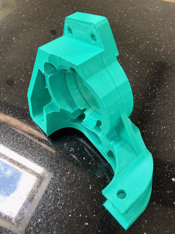
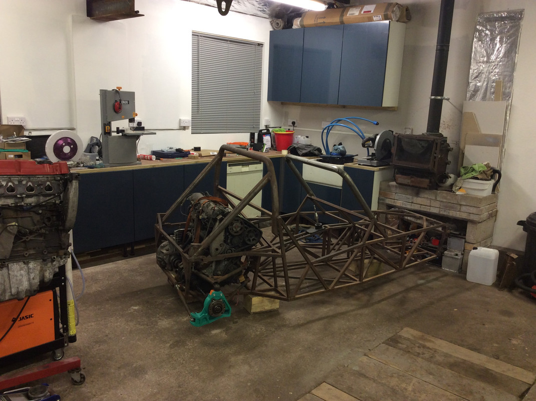
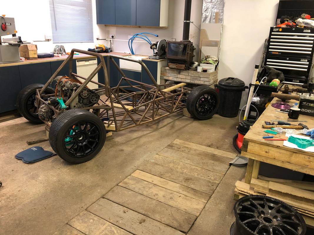
Rob
BenB - 8/5/21 at 07:51 PM
Could that rear arm be a weak point? Perhaps extend the buttressing round onto it? I know less then nothing but that rest arm looks like two parallel
plates which will surely be liable to bending unless reinforced?? Could the very rearmost but be enclosed to turn it into a box section which the
strut sits within? I may be misunderstanding the forces applied to that bit...


 nearly 90 hours on the printer.


