Caber


Rescued attachment Bottom Wishbone2.jpg

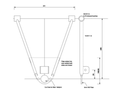
Following some discussions with Shug (and a brief introduction to TIG welding to which I am a total convert!) I have sketched up a proposed design for
lower front wishbones, any coments and suggestions would be appreciated.
Caber


Rescued attachment Bottom Wishbone2.jpg
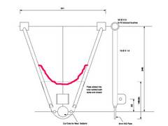
Look pretty much the same as mine, when i posted a while back with mine already made the general consensus was to curve the plate.
So instead of meeting the oval tubes at 90 degress theres a progressive curve to lessen the stress concentration and potential risk of failure at this
point.
Other than that - they look pretty sweet to me....
Geoff
[Edited on 28/11/05 by jambojeef]
[Edited on 28/11/05 by jambojeef]
The intention is to slot the tubes so the plate goes inside and is seam welded top and bottom. The other change is to move the shock absorber pick up
as close as possible to the ball joint to generally reduce the load on the plate, or a least the flexing moments.
If I understand what I am doing (???) the wek point would be at the end of the slot though if this is welded up properly to the plate. If this is
really an area of concern triangula fillets could be welded in here to reinforce this area or I guess you could cut back the plate, I am open to the
suggestions of the wise men of the forum as to which will be stronger.
Caber
The design seem pretty good to me, placing shock mount close to the balljoint reduce the greatest loads here, but I wouldnīt slot the tubes all the
way, only near the ends in order to hammer the tip of the tubes to weld them shut (check the drawing and see if you understand what I mean). I also
would consider 21mm OD 3mm seamless tubing just to be sure. Since you are using a beefy 6mm plate, it wonīt hurt to strengthen the tubes, specially
because there are usually cracks due to stress risers when you have abrupt changes in material thickness
curving the plates seems to be a good idea to cut wheight also, since there is no use for all that material in its internal portion.
sorry I didnīt send the drawwing, I am having trouble to attach images to my reply
here it goes... I hope
Rescued attachment imagem.JPG
Hi,
Seems like a nice enough design but I would advise you to ditch the Lolocost bushes, assuming you are talking about the Nylaspa bushes which I bought
from them a few years ago. They are made of Nylon as the name suggests and aren't of very good quality. I bought the Lolocost wishbones so I
kinda have to use the matching bushes but they are not good and will be one of the first things I will be changing when I get my car on the road.
The other thing to be careful with, as mentioned above, is to avoid stress risers where the thick plate meets the wishbone inboard edges. This is
where locost wishbones tend to fail from what I have seen. Your efforts to move the shock absorber mount closer to the balljoint will certainly help
to remove bending forces but will probably not get rid of them completely. In this respect maybe 6mm steel for the plate is actually too strong
compared with the wishbone tubing. I would either use a thinner plate or thicker wishbone tubes.
Cheers,
Craig.
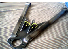
gustavo_brum has the idea but
take a look Flak_Monkeys GTS supplied wishbone the radius on the plate corners should be one you can cut easily using hole saw you already have for
some other bit of the car.
Slotting the tubes other than a few mm at the ends isn't a good idea.


Rescued attachment lowerwishbone.jpg
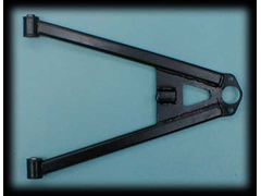
this is the MNR part
not quite as good.
[Edited on 28/11/05 by britishtrident]


Rescued attachment front-lower-wishbone.jpg
Hi Caber,
I must admit, I don't like the idea of slitting the tube, but I do think it's stronger
and looks better to have the join on the centre line of the pipe.
6 mm plate ? Probably a little OTT, and 19 o/d x 1.5, possibly the other way.
I went for 4 mm and 22.2 o/d x 2 and a long sweeping curve to the back edge of the plate.
(see below).
On saying this though, absolutely top marks for having a go and making them.
A true "Locoster".
ATB
Paul G


Rescued attachment w-bone-drawing-s.jpg
Both the GTS and MNR wishbones are made of oval tube. Does this make the tube stronger? I would have thought round tube was stronger. Anyone know
dimensions and wall thickness of the oval?
I was proposing 6mm plate as I just happen to have some:-) I see the point of 3mm wall thicknes with 6mm tube the weld would be pretty equal in the
wall and plate.
If I go to 3mm wall tube do I need so much plate reinforcement? Could I get away with a small piece just big enough for the ball joint and shocker
bracket?
This arrangement will flatten out the spring angle. this increases spring effect if I remember correctly or have i got that the wrong way round?
TIA
Caber
Caber,
I think that the oval tube is mainly used for aesthetic reasons plus a small (ie. very) amount of aerodynamic reasons. The oval tube also mates up
with the bush tubes better than round tubing and probably results in a stronger weld. I personally think the oval tube looks much much nicer and will
be buying wishbones with oval tubing next time around for sure. The GTS 'bones are my favourite from those I have seen so far but I'll check
out other suppliers too when ready to order.
My advice would be not to use the 6mm plate because I think it will be too stiff even when using 3mm wishbone tubing and will produce stress
concentration at the inboard edge. You can buy small offcuts of any thickness of steel at your local Metal Supermarket quite cheaply.
My understanding of the plate is that in theory you wouldn't need it at all if you could design your suspension to have the shocker lower mount
and balljoint coincident with each other. This has practical difficulties but I think Cater ham have a design which comes pretty close. In most
practical cases though the plate's function is to transfer the shock absorber loading into the wishbone as equally as possible and most designs
have evolved towards that of the GTS or MNR wishbone for good reasons and based on real-world experience. You could do a lot worse than copy the key
design points of these into your own design.
Finally, your point about spring angles. Essentially the closer to vertical the spring is, the more spring force is acting in the vertical direction.
Thus if you have a vertical spring you might need a 250 lb spring but if the spring was mounted at 45 degrees you would need something like a 350 lb
spring to achieve the same effect, all other factors being equal. This is a gross simplification of course.
Cheers,
Craig.