
Different Bottom Wishbone
Nisseven - 18/12/05 at 11:09 AM
Hi Guys
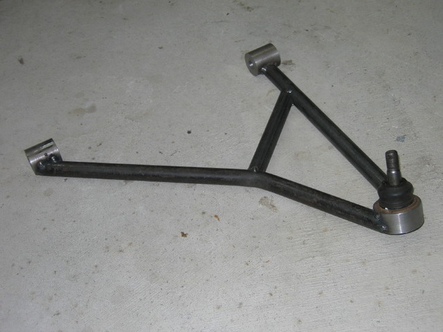
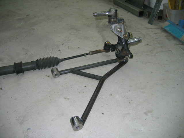
Attached is a Mockup of my bottom wishbone and upright with adaptor for top ball joint. The Upright is Nissan Silvia (sx200) and is rear steer.
The bend in the forward element is neccessary to allow the wheel to turn. The stub axle is very low on the upright hence the centre of the bottom ball
joint is 230mm off the ground. The bottom pivot centre are therefor 105mm from the bottom of the chassis. Plenty of room for the rack but will mean a
different layout for the chassis at the front. I'm not going to worry about that to much till I get the suspension mounting points worked out
properly and will build the chassis to suit.
I must stress that this is only a mock up and the top bracket is also not finished yet.
Bruce

Rescued attachment IMG_0629_2_1.JPG
Nisseven - 18/12/05 at 11:10 AM
Meant to attach two images.

Rescued attachment IMG_0626_3_1.JPG
rayward - 18/12/05 at 11:17 AM
Hi,
are you welding the balljoint to the wishbone on your finished one?, would be a pain when you need to change one.
also, what about a steel plate inside the triangle a the balljoint end, for a bit of extra strength.
Ray
JoelP - 18/12/05 at 11:39 AM
im mate  i remember our old thread about this one
  Which was is forward? My only comments would be two fold with regard to the lower bone.
Firstly, the brace at the bent bit would be better if it went straight to the bush tube rather than a few inches short (i appreciate that, if left is
forwards, it wont be seeing much force and probably wouldnt fail anyway) and also, once its all put together i would try to straighten the bent arm.
It might be possible to compromise the amount of lock and keep it straight.
  Good luck anyway.
Cita - 18/12/05 at 01:06 PM
Hi Bruce,
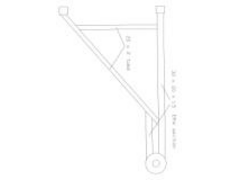
I dont know if this would be an improvement but at least you would get rid of that bended tube which everybody will comment on

Cheers Cita
Cita - 18/12/05 at 01:08 PM
Ooops!!

Rescued attachment Scannen.jpg
JoelP - 18/12/05 at 03:09 PM
id recommend looking in ns devs photo archive, his grasser gets plenty of lock with assymetrical bones, without the need for bends and unbraced nodes.
Nisseven - 19/12/05 at 11:14 AM
Thanks for the replies.
Ray, yes there will be a plate for the shocky which will be able to be mounted much closer to the ball joint than the cortina setups. The ball joint
is not welded but is a press fit into a collar with a circlip, exactly as it is in the donor. The collar on this mock up is machined over size!
Joel. If you reread my text you may grasp the concept. I stated that the rack was rear steer, which means that the rack is to the rear of the bones.
Why does the bend frighten you and what do you mean by unbraced nodes? I see two triangles and of course when the plate is welded in for the shock it
should never bend. It will be made from shed 40 seamless tube which is just under 3mm thick. We have to do that here, where as I read you guys can use
EWT tube. I see in your photo archive a picture of a bottom wishbone which I assume is on your car and it has the shock mounted on a piece of rhs
welded across the end of the bone? With all the excellant posts on here re stress points created by poorly designed shocky mounts I thought this was
questionable.
With all due respect to NSDev his front is entirely different. He has made a great job of his Grasser, but I can see his bottom ball joint, mine is
right inside the wheel, all you will see from the same angle is the end of the wishbone disappearing into the wheel. Makes a big difference to the
lock. Unlike your Cortina Uprights mine will have 10mm scrub against what, around 100mm. What's your opinion NS Dev?
Cita your right about the bend in the tube. Seems to scare the crap outer them.
Bruce Kelly
JoelP - 19/12/05 at 11:58 AM
the node i refered to is in citas drawing. The bones in my archive were made 2 or 3 years ago, before i knew anything about car design, and have been
scrapped recently. In fact, the whole car has.
quote:
I stated that the rack was rear steer, which means that the rack is to the rear of the bones.
Ok, i didnt read every line of your post...
The only problem i have with the bend in your picture is that it isnt theoretically braced as well as it could be. It will certainly be strong enough,
but why not make it perfect? the bar that supports it should join up with the bush eye. As you point out, the bones in my archive are not ideal
(indeed, crap) from a theoretical view (they never failed though), so i cant see why you dont apply the same thinking to yours.
Mine had many faults, the tube was wrong spec, both legs had been cut and rewelded to remove distortion, the shocker bar was daft, and the two sides
weren't symetrical. I only point that out so you cant 
Anyway, i really couldnt give a toss how you make them, you seem to be getting upset so i'll wee off now. Best of luck with them.
The only further posts i shall make on this thread will be if anyone cares to discuss/argue about the technical reasons why the bracing should be one
way or another. Im sure yours will be just fine how they are in 3mm tube, so dont take my past or future comments personally. 
MikeRJ - 19/12/05 at 12:04 PM
Providing the wishbone is made from adequately strong materials I don't see any problems with the design, bar the comment that Joel made about
the diagonal tube joining closer to the bush tube. With that mod it would be quite a "pure" triangulated design with the members in tension
or compression. However, the success of the design could be made or broken on your intended damper mounting location.
Sorry Cita, not keen on your design, IMO there would be a large amount of bending stress at the point there the straight section joins the
triangulated section.
NS Dev - 19/12/05 at 12:20 PM
quote:
Originally posted by Nisseven
Thanks for the replies.
Ray, yes there will be a plate for the shocky which will be able to be mounted much closer to the ball joint than the cortina setups. The ball joint
is not welded but is a press fit into a collar with a circlip, exactly as it is in the donor. The collar on this mock up is machined over size!
Joel. If you reread my text you may grasp the concept. I stated that the rack was rear steer, which means that the rack is to the rear of the bones.
Why does the bend frighten you and what do you mean by unbraced nodes? I see two triangles and of course when the plate is welded in for the shock it
should never bend. It will be made from shed 40 seamless tube which is just under 3mm thick. We have to do that here, where as I read you guys can use
EWT tube. I see in your photo archive a picture of a bottom wishbone which I assume is on your car and it has the shock mounted on a piece of rhs
welded across the end of the bone? With all the excellant posts on here re stress points created by poorly designed shocky mounts I thought this was
questionable.
With all due respect to NSDev his front is entirely different. He has made a great job of his Grasser, but I can see his bottom ball joint, mine is
right inside the wheel, all you will see from the same angle is the end of the wishbone disappearing into the wheel. Makes a big difference to the
lock. Unlike your Cortina Uprights mine will have 10mm scrub against what, around 100mm. What's your opinion NS Dev?
Cita your right about the bend in the tube. Seems to scare the crap outer them.
Bruce Kelly
I don't think there is a major issue with the bend in the wishbone really, particularly not with 3mm wall tubing.
It's not ideal, but then it won't cause any harm either.
The scrub radius thing is similar, it's not ideal by any stretch of the imagination, but then it is not a problem to live with (obviously not on
the grasser, but even on my 7 I don't see a major issue with it)
If that style of wishbone fits in with your plans, use it, there won't be a major problem.
My only comment, and it is not technical but aesthetic, is that the uprights with the modified tops look rather cumbersome and ugly. Will they be
changed for the final version?
Not a criticism as it is better to have something with the correct geometry than something that looks good but it would be nice to have both!
Cita - 19/12/05 at 08:22 PM
quote:
Originally posted by MikeRJ
Sorry Cita, not keen on your design, IMO there would be a large amount of bending stress at the point there the straight section joins the
triangulated section.
No problem mate
It was just an idea.
Cheers Cita
Nisseven - 20/12/05 at 10:26 AM
To JoelP, Sorry for being a bit nasty towards your comments, it's a bit hard to put things in words sometimes and have them sound right. I agree
that the brace could go nearer to the bush and even thought about it at the time. No reason not to do that when I build the real thing. I'm
pleased you rebuilt you wishbones/car, maybe you could post the new ones?
MikeRJ. Your point is echoing JoelP and is noted. The mounting point for the shock will be as close as I can get it to the bottom of the upright
without it touching so should be good design wise.
NSDev. You are right. The scrub does not seem to be to much issue except I had the opportunity with having to construct a mount for my top ball joint
to get it right. I didn't know what was right but from this and other forums it seemed 10mm pos seemed acceptable. The original car had about
this as near as I could measure. Interestingly when I set it up in a wheel I was able to pivot the wheel on the floor and the inner of the bones
hardly moved.
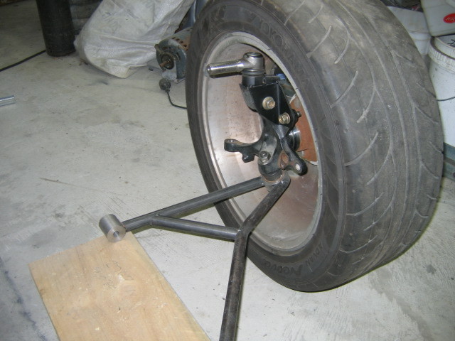
I've posted a few more photos to give you a better idea of how it looks attached to the wheel. I was very concerned how it would look and the
photo did not really do it justice. There will be some minor shaping and trimming when it is welded but I think you will agree some black paint and
the wheel around it are an improvement.
I supose I should mention that there is no disc or calliper attached to the upright and that the bottom bolt on the bracket is one of the calliper
bolts.
Bruce
[Edited on 20/12/05 by Nisseven]

Rescued attachment IMG_0635.JPG
Nisseven - 20/12/05 at 10:28 AM
Straight ahead from front
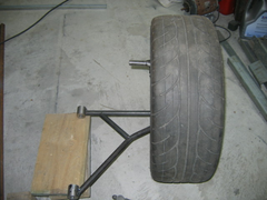

Rescued attachment IMG_0634.JPG
Nisseven - 20/12/05 at 10:30 AM
From top at full lock

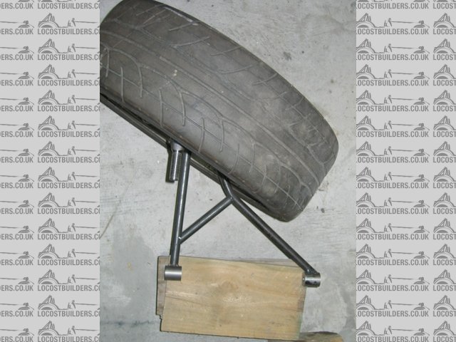
Rescued attachment IMG_0636.JPG

 i remember our old thread about this one
  Which was is forward? My only comments would be two fold with regard to the lower bone.
Firstly, the brace at the bent bit would be better if it went straight to the bush tube rather than a few inches short (i appreciate that, if left is
forwards, it wont be seeing much force and probably wouldnt fail anyway) and also, once its all put together i would try to straighten the bent arm.
It might be possible to compromise the amount of lock and keep it straight.
