
Rescued attachment Front Wishbones.jpg
anyone got pics for the front suspension please?
http://locostbuilders.co.uk/viewthread.php?tid=48105
Any help?
Rescued attachment Front Wishbones.jpg
thanks
do they all need to be that way around, i was thinking rose to replace top and bottom ball joints, didnt know if roses were up to taking weight so was
thinking mounting a rose bearing on lower plate.
you see im looking at fabricating the uprights so would make them rose friendly instead of conversion!
Or am i talking ....... well rubish?
ps you got me thinking about internal mounts now, was going to leave them as bushes!..... thanks!!!
If I did it all again I would use poly bushes on the wishbones - my rose joints failed after 5K miles and I just fitted replacements at Ł25ish each. I definitely wouldn't use them for upper and lower ball joints - they wouldn't last five minutes.
quote:
Originally posted by RazMan
If I did it all again I would use poly bushes on the wishbones - my rose joints failed after 5K miles and I just fitted replacements at Ł25ish each. I definitely wouldn't use them for upper and lower ball joints - they wouldn't last five minutes.


got my eye on mcgill thanks!!
what size type rate were the ones that gave up and was it down to race or road
oh were they on a seven?
With all due respect to McGill, I doubt that a Ł4 rod end will be up to much - I have learned that you get what you pay for where rod ends are
concerned. They might be ok for one or two races but mine is a road car so long life is a priority, although most race car builders that I know tend
to spend over Ł20 - Ł50 per rod end. Have a word with Autosport Bearings and they will give you a spec for your application, also Nick Skidmore will
give you accurate advice. Don't compromise on your suspension - your life literally depends on it.
My supplier says that the failed rod ends were 'good quality' ones but I can't confirm which manufacturer made them because there were
no markings so I am guessing that they not as good as he thought they were. The replacements are made by Aurora with a known spec and load limit. PTFE
liners are a must in any case.
p.s My car is a middy but with similar suspension to a Seven.
[Edited on 11-7-07 by RazMan]
Nitram38 - Are you sure you wouldn't be better off with ball joints on those uprights?
Rod ends are designed for the transmission of loads where the loads are colinear to the axis of the stud, i.e., rod ends are the load points in a
‘two-force’ body that push and pull along the axis of the rod end stud. Rod ends in that orientation (rotated 90 degrees) will be severely compromised
and a ball joint would have more bearing area in the vertical plane imo. I'm willing to be proved wrong though 
Description
[Edited on 11-7-07 by RazMan]
I have to concur with RazMan. Its just a matter of time before the bottom outer rod end will break.
That is if the bump loads are going through the bottom outer rod end before getting to the push rod that I assume is going be in the design.
The only way this can be avoided (and I would like to be proved wrong) is to mount the push rod directly off of the upright which will be tricky to do
at the front.
I have covered this loads of times before in posts that are years old.
Have a look at race cars. Many have rose joints this way around. My F1-2 has them this way around and so far 1400 miles and no problems. 7 ball
joints were designed for a car weighing around 1200 kg originally. My car will be around 500kg.
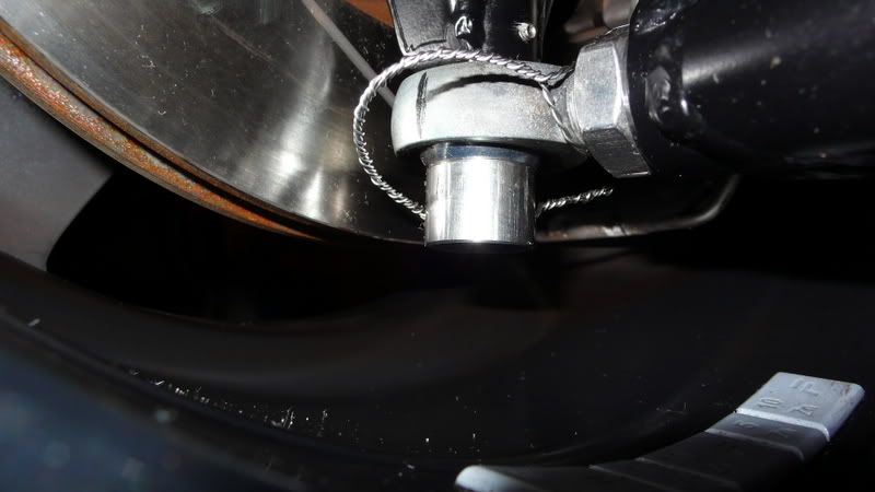
The photos show the car in the building stages so the bolts do not have the washers on that act as a safe guard.
The washers are no ordinary ones either. I use them on the F1-2 and they come from pegasus racing in the U.S.
Here is a photo of the F1-2, a bit big and before anyone comments, the angle of the wishbone is caused by the car being off the floor and not set
up.

Description
Front bottom rod end on Ariel Atom and it doesn't even have a safety washer!
My bolts are drilled for lockwire and I will also be putting a grubscrew in the upright.
[Edited on 12/7/2007 by nitram38]
nitram38 a number of points:
1. Race cars are not road cars the bump loads into the suspension of a road car will far exceed those ever seen by a race car. Racing vehicles are
subject to far more stringent servicing schedules than that for a road vehicle.
2. The load in the joint in question is a function of the g it is submitted too and the unsprung mass it is supporting. The sprung mass of the
vehicle has very little to do with it.
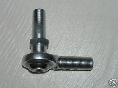
3. Failure of the ball region is not what I would worry about, normally where these joints fail is at the root of the threaded section (circled in
picture below).
4. The picture of the Vortex shows a captured spherical bearing as the bearing for the lower end of the upright. This is a far superior solution to
using a rod end in bending. As the bending loads are taken in the welded structure of the bottom 'A' arm rather than through the threaded
section of the rod end.

Rescued attachment RodEnd.jpg
Read this for further information.
The Atom is a proven road car.
I removed the vortex picture because it is not a good example.
There also lots of other pictures on my hardrive, but I am at work at the moment.
The article you suggested also says that bigger Rod ends would do, but in a racing enviroment, they should be small and that is the reasoning behind
the change.
Quote "Of course if the rod ends are big enough they will not break, but the Design Judges argue that if the system is correctly designed, then
smaller and lighter components can be used, and this has a flow on effect to the sizing of other components"
In otherwords, they will not break if you use big enough rod ends.
My rod ends are 1/2" UNF and are sufficient for the weight of my car.
There are no absolute rules in engineering, otherwise we would not progress.
[Edited on 12/7/2007 by nitram38]
quote:
Originally posted by nitram38
In otherwords, they will not break if you use big enough rod ends.
My rod ends are 1/2" UNF and are sufficient for the weight of my car.
There are no absolute rules in engineering, otherwise we would not progress.
) but my main concern is the
punishment that a road car will give those upright rod ends - the forces couldn't be in a worse direction for the intended design of the bearing.
. I would certainly choose the latter for road use but it would be wise
to speak to a manufacturer to determine the spec required. putting bending loads through rods ends is bad engineering practice regardless of the size of them. they may not fail but without rigorous testing it
would be hard to know when they would fail as cracks in the root of the threads can be very hard to spot and with the large stress concentrations the
crack size before fast fracture can be quite small.
if you want sperical bearings put them into proper apex ends and do all the adjustment at the inboard end where the loads are lower (assuming either
push/pull rods or outboard dampers are used)
Best practice is to use a spherical bearing not a rod end spherical bearing.
This fairly common practice using a special version of the GT 6Triumph (Alford & Adler) upright. Caterham now use this on the Seven
Using this upright saves a lot of hassel, it is very light and has caster & KPI very suited to a light car.
Unlike the small Herald/Spitfire upright the steering arm and caliper brakets are bolt on parts.
OK Stupid question, having read the above article and looked at the images.
How is the Rod end thread in these cases anymore likely to fail that say the thread on the transit drag link that is usually used on the top of locost
wishbones?
Is it just the larger load on the lower wishbone that's the concern?
As to the bearings failing I noticed that McMasterCarr had rod end bearings that they specifically list as thrust rated up to 1700 lbs, although I
could see that instantanious forces in that direction on the suspension might far exceed this.
quote:
Originally posted by britishtrident
Best practice is to use a spherical bearing not a rod end spherical bearing.
quote:
Originally posted by Doug68
Read this for further information.
Top and bottom ball joints are totally different load cases, on the top the transit drag link is not subjected to the spring loads only axial loads.
Also the axial loads on the top ball joint are much lower than those on the lower joint.
I still say Ariel Atom!
Have you got any detail pics of the Atom? I would be interested to see what they do with the front uprights. (Google doesn't come up with much)
id side with martin here, provided he uses suitable washers then he may as well find out if they will work or not. If it does fall apart the washers will save the day and he can then change to another system if he wants. I intend to do mine similarly.
Hi Joel
I think the inference is that the rod end could break at the thread root rather than fall apart, so the washer wouldn't help.
Thats how i read the post anyway?
Al.
Originally posted by JoelP
id side with martin here, provided he uses suitable washers then he may as well find out if they will work or not. If it does fall apart the washers
will save the day and he can then change to another system if he wants. I intend to do mine similarly.
ah there is that, thats down to the material of the main body though. Recently it was pointed out that overtightening the locknut can cause it to
sheer at the threads. 1/2" is a pretty meaty shaft to snap though!
I have a bag full of m10s! 
Given the fact that a Chinese minister has just been executed for allowing lethal medicines to find their way into the supply chains, do you trust
them to ensure that Ł4 rod ends are consistently made from the correct grade of metal? 
quote:
Originally posted by ChrisGamlin
Given the fact that a Chinese minister has just been executed for allowing lethal medicines to find their way into the supply chains, do you trust them to ensure that Ł4 rod ends are consistently made from the correct grade of metal?
Wont make that "mistake" again I guess
quote:
Originally posted by RazMan
Have you got any detail pics of the Atom? I would be interested to see what they do with the front uprights. (Google doesn't come up with much)


I stand corrected regarding application then - if Aerial consider a rod end to be safe on an Atom then an ultra lightweight car like yours should be
also, although I still wouldn't be happy with that setup on my own car (800kg) Without wishing to labour a point though, do you know the spec of
their rod end? Betcha it costs more than Ł4
[Edited on 12-7-07 by RazMan]
Im planning to just use M16 rod ends at the front upright end and be done with it
So far I've just bought branded SKF "industry std" parts, and will replace with better if needed.
Photo is of a very rough mock up while experimenting with front upright geometry
Cheers
Fred W B

Front suspension mock up
[Edited on 13/7/07 by Fred W B]
Apparently it's not all that uncommon for rod ends to fail on the Atom.
http://forum.atomclub.com/index.php/topic,1707.0.html
quote:
Originally posted by RazMan
I stand corrected regarding application then - if Aerial consider a rod end to be safe on an Atom then an ultra lightweight car like yours should be also, although I still wouldn't be happy with that setup on my own car (800kg) Without wishing to labour a point though, do you know the spec of their rod end? Betcha it costs more than Ł4
[Edited on 12-7-07 by RazMan]
Actually, reading through that thread, it appears that many owners are replacing all of the rod ends on their car after only a few thousand miles
(presumably on smooth racing circuits) and Aerial themselves recommend 'competition grade' rod ends for safety.
Quote from the thread "I'll be opting for those kevlar lined Heims, at least for those 2, and the 2 on the front. They are however
expensive...."
At least I have only got four to replace
[Edited on 13-7-07 by RazMan]
I've also been shown these (see picture).
Which apparently are used in dragsters for something.
Anyhow they look darn near perfect for the application I need them for if a bit over sized being 3/4" UNC thread with a 5/8" hole.
They came from here but I'm sure there must be other suppliers of the things.

Rescued attachment rodends1.jpg
Top ball joints on our cars are not really designed for what we use them for either, they are drag link couplings from an antique steering system used on goods delivery vehicles. Some people say the range of motion on them is inadequate but we keep using them mostly without any problems (because they are 18mm thick probably explains that though)
quote:
Originally posted by Peteff
Top ball joints on our cars are not really designed for what we use them for either, they are drag link couplings from an antique steering system used on goods delivery vehicles.
quote:
Originally posted by Doug68
I've also been shown these (see picture).
Which apparently are used in dragsters for something.
Anyhow they look darn near perfect for the application I need them for if a bit over sized being 3/4" UNC thread with a 5/8" hole.
They came from here but I'm sure there must be other suppliers of the things.
Have used 1/2" rose joints on front uprights like that for over 10yr, but on a car that is under 800lbs. The design and chassis pick up points
(inboard whishbone) need to be well positioned. So as the rose joint can be fitted with the maximum (under 1/4" of thread outside of locknut.
Single shear is a killer. IMHO
http://s72.photobucket.com/albums/i187/uphill-racer/?action=view¤t=Fupright.jpg
I don't normally get involved in discussions on this website,because I think the strengths of the locost principle is that members should be
allowed to freely evolve design's which are of their own creation and thus a succesfull outcome rewards satisfaction of doing 'their own
thing'.
However I feel it is important to make some input where I consider 'life or death' parts are being compromised.
I can understand why a rod end would be utilised in the orientation shown in 'nitram 38' photos-it is easy to engineer ,the mount bolt or
pin is directly into the top of the upright and the threaded stem presents itself nicely to a female threaded tube in the wishbone.
This system is often used in race car construction but it is important to understand the type of loads involved and a good race car designer will have
appreciation of the compromises.
Rod Ends(not allowed to call them rose joints any more for fear of breach of trading style)are strongest where the load is perfectly radial,ie where
the load is parallel to the line of the stem such as in a 4-link system.
If the rod end is turned such that the major loading is now axial then the failure load is reduced by a factor of 10.The rod ends shown in Nicam 38
photos are of the inexpensive pressed construction type which have a U.S.R.L (Ultimate static radial load)of about 8,500 lbs - if this rod end is
loaded fully axially(sideways)then the load figure is only 850lbs.
Mention of safety washers is somewhat academic,these rod ends rarely fail due to ball pull out or bolt failure,unless the rod end selected is of too
small size.They normally fail at the root of the stub thread.
The risk of failure is almost inevitable when the rod end has insufficient angle of misalignment to cope with the range of suspension movement...this
is more critical on a road car than a race car because of the greater range of movement required.Designers utilise tapered side spacers so that the
head of the rod end has the greatest range before lock out occurs.Ironically the cheap pressed construction joints have a greater angle of
misalingment(average 20%)than the 3-piece race quality joints(average 12%)though expensive high angle joints are available.
With use of hard shocks and stiff springs the risk of rod end failure is increased because the acceleration of the upright on bump can exceed the
acceleration of the wishbone.this is particularly true when the shocker is mounted well inboard from the upright.
We have been involved with 2 major racecar manufacturers (who both should know better)who experienced lock out of the top rod end ,both experienced
bearing failures of this joint on primary laps of prototype testing.Both used the best quality rod ends from respected suppliers so it wasn't
poor quality product.
In both cases the designers had incorrectly calculated angles of misaligment causing lock out on maximum bump and also the shock loading figures on
hitting race track bumps.
Both resorted to rod ends with 1" stubs and taper spacers to increase angle of misalignment,this cured the problem.
For road use I personally would use the Transit drag link at the top of the upright and Maxi type ball joint at the bottom of the upright.The Transit
drag link has a strong M18 stub,is stress relieved to avoid stress concentration at the thread root,has 20 degree misaligment angle.is fully dust
shielded and is cheap.
Similarly the Maxi ball joint is specifically designed to accept high axial loads and again 20 degree misalignment angle.
Also I would question use of rod ends on the inboard ends of the wishbones,PTFE bushes with stainless tubes will have a much greater life.
Hope this helps.
David Elderfield
Senior designer
Rally Design Ltd
David, thankyou for input. I am sure that your advice will save some builders from premature suspension failure with potentially disastrous results.

I should have added to all my posts, that on my car, the engine is at the rear, so less load on my rod ends.
If you are saying that my cheaper "pressed" rod ends do not fail with the ball coming out, then is is just a small rod diameter that is the
problem.
If you look closer to my photos you will see angled spacer washers so the rod ends don't bottom out.
Nitram 38 what do you estimate the loads are in this joint on your car?
My guesses would be 20kg for the unsprung mass and 40g for the bump (anyone have better data?) giving a force of 800kg.
I'd guess that there's ~40mm of distance between the thread emerging from the tube and the center of the ball, therefore thats 32kgf-m
(230ft-lb) of bending torque on the rod end.
Would you agree or not?
Do you think this sort of loading is acceptable for the component you are using?
Notice the mass of the vehicle doesn't come into the calc as its the wheel (unsprung mass )that goes over the bump and its the wheel that needs
to be controlled by the spring - damper.
I am basing my design on the Aerial atom, not by calculations. They use this set up and same size rod ends, except my car is lighter than theirs.
Do your calcs take into account length of wishbone?
The load you talk of, changes depending on the length of the bones too, as the bending moment is not 40mm as you suggest.
The load is spread the entire length and not focused at this point.
I have seen more broken wishbones than rod ends.
Perhaps you had better talk to Ariel and Raceleda too ?
[img][/img]
Description
[Edited on 16/7/2007 by nitram38]
Lets do some sums for the fun of it, i'll start, feel free to refine if you like.
What loads would we expect the car to withstand? If i drove into a kerb at say 40mph id expect something to break or the tyre to blow out, so lets
assume worst instant loading will be a 3" kerb at 40mph. These figures wont be precise because i intend to guestimate them.
a wheel with a diametre of 20" would hit a 3" kerb approximately 6" infront of the axle centre. Hence the wheel would lift 3" over
a distance of 6". We'll assume a linear rise, even though it wont be exactly.
6" at 40mph is travelled in (17m/s over 150mm) is roughly 0.01 seconds.
Speed the wheel rises is thus 75mm in 0.01 seconds
(im thinking at this point the tyre would probably pop, but i'll go on anyway...)
this is 0.075m in 0.01 secs, or 7.5m/s. To reach a speed of 7.5m/s in 0.01 secs is 750m/s/s, or roughly 75g.
Doug, i assume you discount the weight of the car because the spring allows it not to move? Im thinking it must be more complex than just that,
because that wouldnt take account of spring stiffness - if it was very stiff the car would have to move too, increasing loading etc. I suppose any
spring would compress under that load so however stiff it was the car couldnt raise that fast without breaking something.
Anyway, at best unsprung mass will be 15kgs per corner, so by your method loading would be 1200kgs. I must say im not convinced you can just multiply
the g force by the weight, wouldnt that be the force that the kerb feels?
Brammo, the US manufacturer of the Ariel, seem to have changed their bottom balljoints, as seen in this picture. I don't know if that has
anything to do with the rod ends.

For anyone who doubts the quality of McGill Motorsports rod ends, here is the spec and they are only Ł2.23 each plus Ł0.75 delivery:
CML 8 (1/2” X 1/2” UNF ) Rose Joint Materials Specification ;-
Ball
52100 Bearing Steel
Heat Treated.
Hard Chrome Plated
Precision Ground
Body
Carbon Steel
Protective Coated for Corrosion Resistance
Exclusive Features
Maintenance Free.
No problems of PTFE Liners popping out under high loads.
Radial Static Load Specification
12,224 Pounds
I think that these are over the 8500lbs calculation already stated and the LACK of a ptfe liner is better than buying ones with.
Mcgills ebay shop NTDWM
[Edited on 16/7/2007 by nitram38]
The 40g loading used comes from conversations with I've had with a professional vehicle testing engineer, and is based upon real recorded vehicle
test data. It is severe loading but it is not crash level loading.
Nitram 38, think about the path the load has to take from the tyre contact patch to the suspension mounting point on the bottom wishbone as far as I
call tell the length of the wishbone has nothing to do with it.
Other people have based designs on the Atom on the mid-engine forum there's a guy who did just that and suffered rod end failure from supposedly
good quality items. Thankfully he was at the track and no one got hurt.
Anyway I think the point has been made. Please think really carefully about what you're doing I want to see pictures of you driving your finished
car around and not of a mangled mess after one of the wheels came off.
[Edited on 17/7/07 by Doug68]
Martin, I think that Marcel (Mave) made a very useful point by showing the brammo version of the Atom wishbones.
I don't know if the changes were made for cost, weight or safety reasons, but surely it's worth investigating further.
How about contacting brammo in the US and asking the reason for the difference.
I think people are trying to help you design a safe car, not trying to undermine your concept in any way. Do Is it really that bad to make new or
adapted wishbones?
Still very much looking forward to the results.
Yep, well said, that's my point exactly.
Regardless of whether those 1/2" rod ends are up to the job in your light car:
I think we can all agree that it is not good design practice to load them this way. Eventhough it is very often executed like this, not just by
amateurs, but also by respected companies. And fortunately most of the time they don't cause troubles.
I would feel more secure with a pressed in spherical bearing. And if longevity is an issue, I would prefer the kind that Brammo is using (looks like
VW Beetle part?!?). I'm working on something similar too, but haven't found a nice way to attach those "Brammo/VW" units to a
fabricated upright, because they need a nut, instead of a bolt.
I'm very much looking forward to more updates on Nitram's project, as it seems to be one of those "dream-projects". Everything is
thought out on forehand, parts are sourced and very nicely fabricated before starting the actual build; it's just as I'd like to do it.
Please keep updating!
quote:
Originally posted by Mave
Yep, well said, that's my point exactly.
Regardless of whether those 1/2" rod ends are up to the job in your light car:
I think we can all agree that it is not good design practice to load them this way. Eventhough it is very often executed like this, not just by amateurs, but also by respected companies. And fortunately most of the time they don't cause troubles.
I would feel more secure with a pressed in spherical bearing. And if longevity is an issue, I would prefer the kind that Brammo is using (looks like VW Beetle part?!?). I'm working on something similar too, but haven't found a nice way to attach those "Brammo/VW" units to a fabricated upright, because they need a nut, instead of a bolt.
I'm very much looking forward to more updates on Nitram's project, as it seems to be one of those "dream-projects". Everything is thought out on forehand, parts are sourced and very nicely fabricated before starting the actual build; it's just as I'd like to do it. Please keep updating!
So far nobody has raised the obvious issue of road dirt salt and corosion, even on club racing cars this is a BIGproblem.
In my club racing salad days I always followed the practice of wiping clean rod end bearings with WD40 after every run.
For a rod car I have a strong personal prefference for silentbloc rubber bushes and OEM style ball joints. Using spherical rod end bearings because of
the bling factor is silly but the bling factor rulls the head with too many builders, why else do we see so many cars with vastly oversized brakes and
asthmatic V8 engines far too big for the Seven chassis.
Some contibuters to this thread clearly have a theorhetical grounding in mechanical or structural engineering others with a mechanical background
have learned about it through seeing failures in the unversity of the workshop floor.
The leason I learned from both routes is that in engineering nothing is perfect all is comprimise. Luckily steel is a material with very forgiving
material properties and often allows us to do things that aren't quite theorhetically correct. However the margin can be pushed too far.
[Edited on 19/7/07 by britishtrident]
[Edited on 19/7/07 by britishtrident]
As I said originally, the article at the beginning of the thread said about using rod ends if they were big enough and mine are.
Assumtions of maximum loading has been under estimated by some, some saying that my rod ends break at around 8500 lbs when the manufacturer has
quoted 12500 lbs as the maximum.
Length of wishbones have also not been taken into account as this does have a bearing on these calculations.
My wishbones are around 450mm long.
I have spoken to Billy of McGill Motorsports (via email) who has been racing for 15 years in Brisca Formula 2's.
He said that he has seen their cars driven into concrete walls and wishbones literally bent underneath the car and has never seen a ball pop out of a
rod end.
The rod ends never break at the thread unless they are driven into a concrete wall at 90mph!
He then goes on to add:
"Interesting the talk of Maxi Ball joints ...we used them for 5 straight years and the ball pulled out of the socket dead easy when colliding
with the wall - causing the entire corner to attempt to go under the car and write off the Ł 140 Ledas most of the time as they were next in
line...
A change to the stub axle design (we have used very similar designs to yours for several years and they are bombproof) which was based initially on
the cortina (too weak) and then changed to the Sierra (very tough) and then to the more refined version of something very similar to yours."
My take:
In a high speed accident, you want things to break off the car.
Parts breaking off cars reduce the injury to the driver. Formula cars are designed to lose weight in an accident, losing their wheels and even their
engines.
There are limits to everything, even sperical bearings.
In regards to the ball joints mentioned, I have seen many a mini or maxi at the side of the road with one of it's wheels at an akward angle.
I doubt that these car's suspension come under the same scrutiny that my suspension does, everytime I drive my car.
I can even see my rod ends in action on my car, from the drivers seat.
quote:
Using spherical rod end bearings because of the bling factor is silly but the bling factor rulls the head with too many builders, why else do we see so many cars with vastly oversized brakes and asthmatic V8 engines far too big for the Seven chassis.
quote:
Originally posted by nitram38
"Interesting the talk of Maxi Ball joints ...we used them for 5 straight years and the ball pulled out of the socket dead easy when colliding with the wall - causing the entire corner to attempt to go under the car and write off the Ł 140 Ledas most of the time as they were next in line...
quote:
Originally posted by rally design
I don't normally get involved in discussions on this website,because I think the strengths of the locost principle is that members should be allowed to freely evolve design's which are of their own creation and thus a succesfull outcome rewards satisfaction of doing 'their own thing'.
However I feel it is important to make some input where I consider 'life or death' parts are being compromised.
I can understand why a rod end would be utilised in the orientation shown in 'nitram 38' photos-it is easy to engineer ,the mount bolt or pin is directly into the top of the upright and the threaded stem presents itself nicely to a female threaded tube in the wishbone.
This system is often used in race car construction but it is important to understand the type of loads involved and a good race car designer will have appreciation of the compromises.
Rod Ends(not allowed to call them rose joints any more for fear of breach of trading style)are strongest where the load is perfectly radial,ie where the load is parallel to the line of the stem such as in a 4-link system.
If the rod end is turned such that the major loading is now axial then the failure load is reduced by a factor of 10.The rod ends shown in Nicam 38 photos are of the inexpensive pressed construction type which have a U.S.R.L (Ultimate static radial load)of about 8,500 lbs - if this rod end is loaded fully axially(sideways)then the load figure is only 850lbs.
Mention of safety washers is somewhat academic,these rod ends rarely fail due to ball pull out or bolt failure,unless the rod end selected is of too small size.They normally fail at the root of the stub thread.
The risk of failure is almost inevitable when the rod end has insufficient angle of misalignment to cope with the range of suspension movement...this is more critical on a road car than a race car because of the greater range of movement required.Designers utilise tapered side spacers so that the head of the rod end has the greatest range before lock out occurs.Ironically the cheap pressed construction joints have a greater angle of misalingment(average 20%)than the 3-piece race quality joints(average 12%)though expensive high angle joints are available.
With use of hard shocks and stiff springs the risk of rod end failure is increased because the acceleration of the upright on bump can exceed the acceleration of the wishbone.this is particularly true when the shocker is mounted well inboard from the upright.
We have been involved with 2 major racecar manufacturers (who both should know better)who experienced lock out of the top rod end ,both experienced bearing failures of this joint on primary laps of prototype testing.Both used the best quality rod ends from respected suppliers so it wasn't poor quality product.
In both cases the designers had incorrectly calculated angles of misaligment causing lock out on maximum bump and also the shock loading figures on hitting race track bumps.
Both resorted to rod ends with 1" stubs and taper spacers to increase angle of misalignment,this cured the problem.
For road use I personally would use the Transit drag link at the top of the upright and Maxi type ball joint at the bottom of the upright.The Transit drag link has a strong M18 stub,is stress relieved to avoid stress concentration at the thread root,has 20 degree misaligment angle.is fully dust shielded and is cheap.
Similarly the Maxi ball joint is specifically designed to accept high axial loads and again 20 degree misalignment angle.
Also I would question use of rod ends on the inboard ends of the wishbones,PTFE bushes with stainless tubes will have a much greater life.
Hope this helps.
David Elderfield
Senior designer
Rally Design Ltd
Quote "In regards to the ball joints mentioned, I have seen many a mini or maxi at the side of the road with one of it's wheels at an akward
angle."
Personally I have repaired more than a couple of of Minis and other larger BL FWDs with pulled out ball joints.
In the Locost front suspension the Maxi ball joint is loaded the wrong way --- it is pulled out rather than pushed in -- it is a generously designed
ball joint with good safety margins so we get away with it.
Mr. Elderfield put the words down before I saw this thread.
I agree wholeheartedly.
Martin, that setup is an 'accident waiting to happen'. Hope you don't take out a mob of pedestrians at a bus stop when it does.
The Ariel is not a good example, and the yanks have obviously spotted the poor (? downright reckless and stupid) engineering (?? no intelligent,
qualified engineer would put his name to such a design), and put it right.
The Ariel design with the rodend would never in a million years, achieve full EC Approval for roadcar homologation. This shows yet another
shortcoming in SVA procedures, allowing this dangerous stuff onto the road.
In my racecar work, I have always used spherical bearings in bespoke housings, at the end of load bearing wishbones. With full failure of the joint
itself, the housing would never allow the system to come apart.
Do yourself a favour, and redesign that setup, with safety and common sense in mind, first and foremost.
Cheers,
Syd.
Syd, I have heard all the blah blah on this over and over, yet no one has commented on why Raceleda use rod ends this way?
How many broken rod ends have you seen?
I bet if you have seen any it is because they were too small or they were the result of an accident and not the cause?
I am happy with my decision.
Description
[Edited on 22/8/2007 by nitram38]
quote:
Originally posted by nitram38
Syd, I have heard all the blah blah on this over and over, yet no one has commented on why Raceleda use rod ends this way?
How many broken rod ends have you seen?
I bet if you have seen any it is because they were too small or they were the result of an accident and not the cause?
I am happy with my decision.
Description
[Edited on 22/8/2007 by nitram38]
Then I guess that the "professional" A1 GP cars must be getting it wrong too.
And they are only using 10mm rod ends:

A1 wishbones

Description
[Edited on 22/8/2007 by nitram38]
Just to chuck in my twopennorth!
I'm not going to argue the pro's & cons of the engineering principles involved, but can confirm that my front suspension which is lifted
direct from a Hawke DL19B Formula Ford 2000 chassis is identical to Nitrams setup. I can also confirm that certainly up until very recently Van Diemen
were still using this arrangement on their FF chassis. If it will withstand the racing loads applied by slicks, a sticky track surface & the odd
wheel banging session then I'd be pretty amazed if you could break a large joint (on a light car)such as Nitram's in road use other than by
smacking it into a kerb or similar.
That said for the production Furore I am using the usual poly bushes, simply because they are ar more suitable for road use, requiring less checking,
mainteneance etc.
I have to say my front "rose joints" show no wear whatsoever, yet the rear ones which are mounted the other way do have a tiny bit of
movement in them.
If it such a terrible design fault & "an accident waiting to happen" then there are an awful lot of dangerous race cars out there!
Surely they are still using the same basic principle in F1?
Russ, alot of people still haven't considered my car design.
My engine is at the rear and 1/2" UNF rod ends are more than enough for the front of my car.
They probably think my engine is over the front wheels.

Description
[Edited on 22/8/2007 by nitram38]
quote:
Originally posted by nitram38
Then I guess that the "professional" A1 GP cars must be getting it wrong too.
And they are only using 10mm rod ends:

The difference with the A1 GP cars is the way the joints are loaded.
Spherical rod ends are most effecient (strength to weight) when loaded in tension (and to a slightly lesser extent compression).
The A1 GP cars have those inner joints loaded in tension and compression NOT bending. The design could be improved by using spherical bearings in
housings.
John
PS Sorry I resurected this post, I have been away from my computer for 5 weeks and thought the subject important enought to commenton.
Rodends on the inboard end of wishbones, and the top outer, are quite acceptable. Geez, I've designed that way for years, along with many others
much greater than me. The loads are radial, that's what they are meant to do.
Lower outers, with the axial/transverse loads, need a very different approach. You'll find that every car at LeMans, and F1(for the little they
count), use sphericals in a housing.
That pic of the A1 car doesn't show the lower outers. Or are you confused as to what I am talking about, and which end of the wishbone I'm
referring to?
In the end, you make what you think is best and safest.
And as I said previously, just make sure it's you you're killing when it breaks, and not a crowd on the pavement.
It's instances like this that need an Aus type rego system, where an engineer has to personally sign off your work. No engineer would put his
reputation and future on that design and use of a rodend for road use.
Race it if you must, and replace the ends after every meeting, as others do with the ends used in normally accepted practice and application.
Just don't put it on the road.
Cheers,
Syd.
Sorry to disappoint you but nearly 2000 miles on my existing car and no problems.
I even had the misfortune of using the concrete section of the M42 a few weeks ago where the undulations cause me some serious bumping for about an
hour.
I can only liken it to a cobbled road at 70mph.
I hate all of the scare tactics used here as they are just that.
If you want a nice safe car, buy a volvo.
I've seen more bent wishbones on 7's than I have seen broken rose joints.
If you go back through this post you will find a reason that sperical bearings are used in a particular racing formula. It was because competitors
were using undersized rod ends to save weight.
The article also went on to say that using the correct size rod end for the load would have been ok.
Are you saying that because you look at something, then you know that it will break.
Syd, show me some calculations based on my previous specs and then maybe you will convince me.
Radial Static Load Specification is 12,224 Pounds, to get you started!
[Edited on 22/8/2007 by nitram38]
One of the benefits of the internet is the availablity of free advice from people much more experienced than us. However we are all free to ignore
others peoples experience and choose our own way.
However just because things have been OK does NOT mean things can not be improved. People giving advice generally do so not to show off how much they
know but to help others build better cars.
My advice is to listen to these people, analyse what they have to say, analyse the engineering principles and not be too proud to say, my design could
be improved.
You could also buy all of Carroll Smiths books and read and understand them. But would you accept what he says.........
I totally understand what you are saying, but I have a hard time accepting blanket comments and absolutes being quoted.
Everything can be improved.
Talking of improvements, how has the 7's aerodynamics been improved since it's conception? Not much!
Are people using gold plated maxi ball joints? Don't think so!
How many people have built their cars from brand new parts? Not many!
I could go on.
Read this article right to the
end. Particlarly "Of course if the rod ends are big enough they will not break, but the Design Judges argue that if the system is correctly
designed, then smaller and lighter components can be used, and this has a flow on effect to the sizing of other components"
While it does agree with the comments made here, it also goes on to say that using larger rod ends will do the job.
The disadvantage of sperical ends are that of adjustment and the use of shims.
No chassis can be that accurate, so rod ends give the required adjustment.
Just like the article, there is no absolute in engineering.
One solution can cause other problems.
Where do you stop?
[Edited on 22/8/2007 by nitram38]
[Edited on 22/8/2007 by nitram38]
What does SVA man says?
if he questions the rose joints and you prove that you have done your homework of analyzing the loads expected and fitted joints with a decent safety
factor threwn in, you may get away with it.
In the end, as posted somewhere else, there are other areas in the Locost Way of life that are more dangerous like not being seen by other car drivers
in a rather exposed driving position
That`s MHO...
My car passed sva and no comments were made about my rod end suspension.
Martin, if you read what I have just written, I point out that examples such as yours, passing SVA and being allowed on the road, HIGHLIGHTS the
serious shortcomings of the whole SVA system.
In some ways, I would welcome an Aus type system here. It would get the majority of the poorly engineered examples of cars and aftermarket parts off
the road.
Re calcs....Safe working max load for a rodend in axial load is 10%. For your example, this is 1.2k lb's+/-. As a not too large
pothole/bump/speed bump can give a 10g jolt to the system, then your corner weight would have to be around 120lb's.
Now tell me you think that your design is safe.
Cheers,
Syd.
Some people think they know, some know, and some are still willing to keep learning.
10% of 12,224 lbs is 1222.4 lbs or have I missed something?
And by the way I can read and I understood your previous posts.
What ever you think of sva, my car was passed as road worthy over a year ago and continues to stay that way regardless of all the theoretical
calcs.
[Edited on 22/8/2007 by nitram38]
The Formula Student article sums it up very well.
The standard of design is improving at Formula Student as I witnessed this year as a Design Judge Team Leader.......
And the bit about bigger rod ends is not valid too?
quote:
Originally posted by nitram38
10% of 12,224 lbs is 1222.4 lbs or have I missed something?
, lbs/lbf = poundforce, I've been told, but then I'm mainly metric.
OK, where does the 10g come from?
Do you mean that a force of 10g is on the joint?
Is this a guess or a proven actual force that the average road car will endure?
hi,
I think there are some misconceptions about suspension loadings here... but let me start from the begining..
for me (and I am in the process of designing a similar suspension myself, using presseed in spherical bearings..) there are 2 questions:
1. what forces will that joint see
2. rod end / spherical in a fixed housing / ball joint dillema....
someone here said that the rod end in question will see only shock loadings that are proportional to the shock and suspended weight (i.e. weight of
the wheel... ) which is not eaxctly the right way of looking at it....
the rod end in question has 3 major forces on it..:
1. radial force towards the car, from cornering
2. radial force towards the back, from braking
3. Axial force downwards, from the reaction of the spring, since the spring is connected to the end of the A arm, via pushrod or direct...
when standing still the axial force is equal to the corner weight of the car minus the weight of the wheel/upright/brake combo. bigger problem is what
happens in bump... well, you just have to decide how tough you want to make it.. I have read from people in the industry that 5g vertical is about ok
for a road car (not production road car... ) but for the sake of argument let's say 10g....
also, you can say that you will see only 1.5 g from braking, but since you will hit potholes, you have to accont for more g's for both braking
and cornering... but let's only concentrate on bump and axila force right now, as this is where the discussion has been heading..
there are two questions right now:
a) will the spherical take it
b) will the threaded rod end take the axial force, since it is in some major bending
since the spherical bearings have axial rating of about 20-30% of the ultimate radial, the axial component is the most interesting... the spherical
that I am thinking about for the lower A arm is 14mm, has radial dinamic rating (dinamic is lower rating than static, but since the spherical will see
constant work...) of 50 000 N. This particular bearing is rated for max 30% for axial loads, but let's say, 20% or 10000 N. that would mean that
at 10G it will be ok for corner weight of 1000 N or , 100 kg... of course, you could always go for 16mm which would mean about 120 kg corner weight at
10G...
the second problem is will the rod end housing take it.... well, for some people it works, I am a bit sceptical and will go for spherical bearing
pressed in the A arm... this way I can make it much stronger since I have to connect the pushrod to the A arm...
as for the ball joints as a preffered solution.... ok, but I would like to read some technical specifications for the various ball joints... with
sphericals I at least have data available...
quote:
Originally posted by JB
The Formula Student article sums it up very well.
The standard of design is improving at Formula Student as I witnessed this year as a Design Judge Team Leader.......
Single shear isn't a problem if all the sizes are increased to an appropriate level, after all this is the way volume manufacturers use to mount
ball joints and coil spring damper units
However in most amateur constructed vehicles with joints mounted in single shear the diameters chosen are well below anything I would consider.
Mounting rod ends in a bending + shear mode is however a different issue, this really isn't a good way to do things. I have never seen a rod
end fail in this mode (except through collision) but I have seen them bend.
Remember you have to build your car to withstand contact with kerbs, potholes, drain covers bricks and anything else urban roads or chavs can throw at
you.
[Edited on 23/8/07 by britishtrident]
quote:
Originally posted by nitram38
OK, where does the 10g come from?
Do you mean that a force of 10g is on the joint?
Is this a guess or a proven actual force that the average road car will endure?
britishtrident, no bending or loosening of my rod ends after one year/2000 miles of use (and some serious potholes), so I guess that my set up is big
enough for the purpose (which is what I have said from the beginining).
Using Rod ends over sperical has one big overlooked benefit and that is adjustability.
For an amateur builder this is a necessity because no chassis is that accurate, so adjusting the suspension is easier.
I have n't hit any curbs, but that is perhaps down to being an experienced driver and also the fact that I can see both front wheels from the
driving position.
It also means that I can keep an eye on my suspension while it is in motion.
This made setting the shocks up a doddle as I can visually see bump on my wheels.
When I first drove the car, I had the front anti-roll bar connected, but this was too stiff for road use. Now it is disconnected and should only be
used if it goes on a track, but I still think that it might be overkill there.
[Edited on 23/8/2007 by nitram38]
Update:
If you absolutely can't use rod ends in shear, why do they make these:
Available from Mcgill Motorsports on
ebay
A man could quite easily be the same way as that departed scotsman,  but......deep breath and remain calm.
Dear Martin,
That rodend in the picture above is designed and made to act with a radial load.
It's the stud THROUGH the rodend that's being put in shear.
It is made specifically for putting on the end of a steering track rod, at the upright end. And does the same job as an outer track rod end. I specify
and design similar items in my work.
Without meaning offense, you are a much better welder than engineer, which you obviously are not trained at.
Stick to your strengths and do what you know best, and stop trying to outsmart the people who do this stuff for a living. There's a couple of
others on here who appear to do so, as well as myself.
The hole you are digging is getting deeper. Learn from what has been suggested, put it to good use, and move on.
Cheers,
Syd.
You'll also find those joints used on the front and back stay bars(sometimes called 'radius rods' ) on solid axles, on USA (and Aus)
circle track cars. In that application, they still have the ball joint in radial load, and the stud in shear.
[Edited on 23/8/07 by Syd Bridge]
[Edited on 23/8/07 by Syd Bridge]
Syd, I am not going to discuss this anymore as you are obviously superior to me (except for welding).
At least I am willing to explore and discuss these matters and not bash people over the head with my qualifications.
Don't bother replying as I will be unsubscribing from the topic.
This going round in a Mohr's circle.
This is neat http://www.engapplets.vt.edu/Mohr/java/nsfapplets/MohrCircles2-3D/mohrcircles2-3d.htm
[Edited on 23/8/07 by britishtrident]

lwb
I'm convinced. I now want to do something like this for a lower wishbone
Cheers
Fred W B
At least one person has learnt from this, and now knows when they're on a winner, and another a loser! Funny old world, isn't it?
Cheers,
Syd.
It's funny how different people are. I have a 5/8" NMB Spherical bearing pressed in (with Spiral Retaining ring and Large safety washer)
that has an axial load rating of 8000 lbs and I still give it a second look... (On an 850lb Track Only BEC)
I can see this discussion going on until the wheels come off it!
I've been resisting posting that for days, but in the end the urge got too much, sorry.
[Edited on 24/8/07 by Doug68]
Interesting read here http://www.formulastudent.de/academy/pats-corner/advice-details/article/pats-column-rod-ends-in-bending/
quote:
Originally posted by nitram38
britishtrident, no bending or loosening of my rod ends after one year/2000 miles of use (and some serious potholes), so I guess that my set up is big enough for the purpose (which is what I have said from the beginining).
i wouldnt use a rod end for that type of application, i had the centre part come through the outer part,the washer that was meant to prevent it going
through didnt,its only a press fit your relying on
rod ends are only suitable for push pull loads along the stub direction as rd dave points out there are other better options
My understanding of this discussion is it is about which way sphericals should be loaded to get the greatest strength for weight, ie the optimum
design. Many solutions work and last. However there are better ways of designing parts.
For example, single shear works but it is so much better structurally in terms of weight to use double shear.
Suspension mounts on the chassis are put into the middle of an unsupported tube.... it works but would be so much better if the mounts were into a
junction of tubes.
Bent tubes are used in chassis without supporting the bend. Again it works but the design could be improved.
Often rod ends loaded in bending work with no problems however with a change in design they can be loaded in tension and compression allowing smaller
lighter parts OR a greater saftey margin from fatique and one time overload failure.
Calculations in my mind are pretty pointless due to the problem of knowing the loads going into the system. It is better in my mind to stick to good
design (which basically means reducing stress raisers) and then use sizes that have been used for years.
My car was built this way. However I do now realise that I have some rod ends in bending on my rear uprights. I didnt know any better at the time but
because I read and was willing to take on board the knowledge of those who do know better I learnt.
John
[Edited on 29/8/07 by JB]