Digger Barnes
|
| posted on 5/5/04 at 06:57 PM |

|
|
Optimal setup
As some of you may have noticed I have been working on a suspension geometry simulation program. This has been to teach myself how it all works. I am
now fairly happy with the outputs from the program and I think I am now ready to actually begin to use it to help me design my suspension for the
front and rear.
So now has come the time to ask some questions from the oracle of knowledge that is locost builders.
So here it is: I am intending to use my locost in RGB cat C racing and a little road use (with different bell cranks for the inboard suspension to
raise ride height and reduce effective spring rate). So what I need to know is what am I looking for in terms of camber change in bump, droop, roll
and combinations thereof for racing and the road (my primary concern is to set up for the track with acceptable handling for the road by changing the
above mentioned settings along with static camber).
Please Please Grovel Grovel I need help then I can continue with my design.
Cheers
Gareth
|
|
|
|
|
stressy
|
| posted on 6/5/04 at 06:20 AM |
|
|
Dont mean to state the obvious but if i understand your question corectly then the answer is zero in all cases.
No really, you will set the suspension static geometry for running straight based upon the type of tyre you are using avon vs. yokohama etc. (is thre
a control tyre?)
This setting should be ideal for optimising grip, self aligning torque and spring rate.
Any deviations from this will change the ideal tyre patch profile. This is yet another factor that must then be taken into account.
On a practical scale there are mechanisms such as the Dax camber compensation system and the Radical Nik links which try and minimise camber change by
floating links but otherwise you just have to deal with it as best you can.
At the most basic level work out the maximum camber the tyre can live with and design your suspension so that the set up you have will only go to this
state at the most adverse loading expected during racing and set the static appropriate to that.
I havent spotted your other posts yet on suspension design, are you using special wishbone geometry as well???? what rear end are you going for???
|
|
|
Digger Barnes
|
| posted on 6/5/04 at 07:54 AM |
|
|
Cheers stressy.
I believe the control tyre will be the Yokohama A048R for the class I am looking at. If you have any information on the tyre charachteristics for this
I would be interested. I suppose I should have a hunt around and even give them a call to see what info I can glean.
Yes it would be nice for 0 camber change most all situations. What Iwould like to know is how well have others managed to design their suspension for
camber change.
Obviously it is a trade of between better camber in roll or bump/droop, but would I be better off optimising roll more than bump/droop as the tracks
should be way flatter than the road?.
As to the rear end of the car it will be IRS with inboard shocks driven with either a push or pull rod (undecided on this yet, but will do a lit
survey and an analysis to see what is best for my situation)
|
|
|
stressy
|
| posted on 6/5/04 at 09:00 AM |
|
|
A Can of worms at the ready
Dont forget bump means brakes unless large amounts of antidive are present, and lots of antidive means massive understeer if you touch a rumble
strip.
Also at the rear dont forget about antisqaut.
You need to comprimise for acceleration, braking and cornering.
If your running a light car you may also want to look carefully at unsprung mass, i would personally go live axle rear end and rocker arm front.
|
|
|
Digger Barnes
|
| posted on 6/5/04 at 10:05 AM |
|
|
Live axle mmm. I already Have a sierra LSD etc hence the IRS (I know dedion is possible).
As to car weight it will be as light as possible. I am aiming for around 400Kg (maybe a bit more depending on roll cage design) the race minimum
weight is 530Kg so I should be able to ballast the car to help with weight distributions.
I will mill the uprights from aircraft grade billit aluminuim to keep the unsprung weight to a minimum and use alloy calipers (again still undecided
whether to use bike units with bike rear discs).
Yep I agree it is a whole can of worms and as I don't have the track experience so I am having to rely on other peoples.
But what I do have is the ability to model the car as well as I can (own software, CAD, Ideas and Nastran). So I hope with input from experienced
individuals I hope I can come up with a car that handles reasonably well.
[Edited on 6/5/04 by Digger Barnes]
|
|
|
britishtrident
|
| posted on 6/5/04 at 02:44 PM |
|
|
It is a can of worms very often a car with all the wrong suspension geometry can a have brillant handling and set fantastic lap times --- just look at
the lap times a Davrian can with swing arms on the front and semi-trailing arms at the rear. In the case of Locosts I strong suspect that most cars
are set up so stiff that geometry dosen't matter much and much the same can be said of unsprung weight.
Part of the reason for this is since the original Lotus Seven S1 tyres have got broader and the aspect ratio lower so increasingly any change of
camber will reduce the grip so much that the suspension has to be set up bone hard to prevent any significant roll, squat or dive.
|
|
|
pbura
|
| posted on 6/5/04 at 09:31 PM |
|
|
Gareth,
Didn't know you were going for an ultralight!
I'm pretty sure that the very lightest option is a solid axle, depending on which one you buy. Isn't the Escort axle (per the book) only
about 100 lbs.?
Not to dissuade you; I'm doing an IRS with inboard shocks, more so I can use the shocks than save any weight. I'll be patterning the rear
much after the Leitch (more pics in my archive):
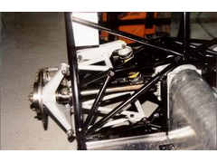 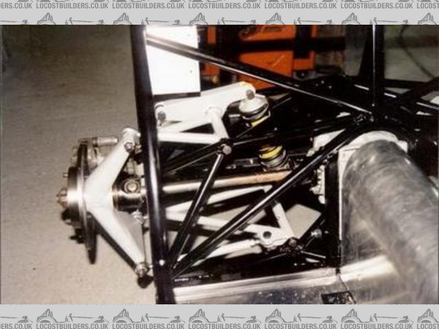
IRS w/ inboard shocks
You may have noticed already that when you shoot for perfect camber control in bump and droop, the roll camber goes to hell, and vice versa.
I've found that camber control is pretty much a function of swing axle length. Short SALs give excellent results in roll, and long ones are
better in bump/droop.
The Locost has a SAL of about 80", which would be considered to be on the short end of moderate, I think. I believe the Locost is a good
compromise design, and would be a good benchmark to measure your design against.
MikeP has analyzed the Locost front suspension thoroughly, and has drawings you can lift the coordinates from. His geometry page is here:
http://www.7builder.com/SuspensionGeometry/
I've done some work with the Locost design, too, with slightly different dimensions but similar results:
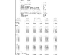 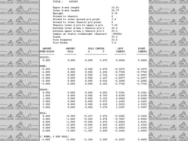
Rescued attachment LOCOST.jpg
Pete
|
|
|
cymtriks
|
| posted on 6/5/04 at 09:58 PM |
|
|
I've already used Nastran to stress the chassis and improve it. My double Y braced chassis on the Photos section is the result. If you look
through my posts in the chassis section you can read the thoughts behind this and other builders comments.
The book chassis has between 1200 and 1400 ftlbs per degree of twist depending on the build. My chassis mods with a book style R tube engine bay brace
is around 2400. The double Y braced engine bay design has around 2700. FYI an Ultima is about 3300 and an Elise over 7000.
Regarding suspension Caterham have experimented with an all independant suspension design with roll centre heights of 65mm (rear) and 30mm (front).
The Deon version was 120mm and 60mm. The Elise has roll centres at 75mm (rear) and 30mm (front).
The camber change on the Elise was 0.31 degrees per inch at the front and 0.45 degrees per inch at the rear. This is very close to the recommendations
given by Costin (of Cosworth) of roughly 0.333 and 0.5 respectively for midengined race cars.
I'm still thinking about this issue but I've seen some figures for the Mazda MX5/Miata and the RX8 and these imply that camber change is
greater at the front on these cars. The MX5 suspension gains 0.9 degrees per inch at the front and 0.4 at the rear.
If anyone knows why the camber change is bigger at the front on the MX5 but bigger on the rear on the Elise I'd be interested to know.
|
|
|
pbura
|
| posted on 7/5/04 at 12:42 PM |
|
|
Interesting discussion about rates of camber change on an engineering forum:
http://www.eng-tips.com/gpviewthread.cfm/qid/52395/pid/800/lev2/6/lev3/35
After reading it, I was impressed with the Locost's setup.
F1 cars have lower rates of camber change, but then again they are used on superior road surfaces and can stand harder springing, even without regard
to aerodynamics.
Pete
|
|
|
britishtrident
|
| posted on 7/5/04 at 02:39 PM |
|
|
quote:
Originally posted by pbura
snip
F1 cars have lower rates of camber change, but then again they are used on superior road surfaces and can stand harder springing, even without regard
to aerodynamics.
I would put it even more strongly F1 one cars have NO suspension movement to speak of its all in the tyre sidewalls. It puzles me a bit when I see
F1 style equal length wishbones copied in lesser formula particularly those without wings or other aero down force such as Formula Ford. perhaps the
reason for this lies in the use of an effective rising rate suspension layout ensuring that the suspension rarely goes near full bump.
Almost 30 years back Ferrari built a test F1 mule with a composite beam axle at the front and a de Dion at the rear it was rated to have the potential
to give as good handling as the then current F1 but of course any developments in that line were killed stone dead by coming of the Ltus 78 & 79
and the sudden the need to generate underbody down force.
[Edited on 7/5/04 by britishtrident]
[Edited on 7/5/04 by britishtrident]
|
|
|
pbura
|
| posted on 7/5/04 at 06:43 PM |
|
|
While I was out and about this morning, I was thinking about the F1 setup and realized that I was speaking some nutsack earlier.
With the lower rates of camber gain, F1 cars are actually better prepared to handle bump than roll. We know that their degree of bump is practically
non-existent, so they must roll even less.  This has got to be the result of very low Cg. This has got to be the result of very low Cg.
I'm thinking that a racing Locost, with a very low ride height and lots of roll stifness, could also make do with less camber gain in roll than
'book', thereby gaining better traction in acceleration and braking.
This refers to the front suspension only as the book Locost has a solid rear axle, so no camber concerns at that end.
Been thinking about the comparison of the MX-5 to the Elise, also, and the difference in F/R camber gain must be due to weight distribution. The
middie Elise is rear-heavy (62/38) so needs better rear traction in cornering, while the 50/50 MX-5 can make better use of traction for
acceleration.
Edit: I didn't say nutsack! Chris!!! Crasser than b*ll*cks, IMO.
[Edited on 7/5/04 by pbura]
Pete
|
|
|
britishtrident
|
| posted on 7/5/04 at 07:05 PM |
|
|
Re Comparing Elsie and MX5 you Pete is about the weight distribution also because of this the the roll couple distribution has to different, I
wonder also if available space for the the top wishbone link on the Elise might also be limited.
It might be worth finding out what static camber both cars are running.
Digging into memories of the original Elan out it had very little camber change on the rear because of the Macpherson/Chapman strut. The Front
wishbones were the the usual 2/3 ratio but couldn't have been much different anyway because of the large ammount of kpi built in to the
Herald based front suspension.
[Edited on 7/5/04 by britishtrident]
|
|
|
Digger Barnes
|
| posted on 8/5/04 at 09:22 AM |
|
|
mmm all very interesting folks.
It gives me something to aim look into.
Yes Pete from reading the live rear is supposed to lighter than the IRS setup, but is this still true if I am using alloy uprights and hubs with bike
4 pot calipers and disks? (Not that this is the route I will be definitely taking).
Cheers Cymtricks I have had a look though your FE stuff very interesting, I have taken note of your mods.
British Trident and all very interesting the comparison between the different good handling motors, this sort of info is invaluable to help decide on
the final setup.
|
|
|
pbura
|
| posted on 9/5/04 at 02:10 PM |
|
|
quote:
Originally posted by Digger Barnes
Yes Pete from reading the live rear is supposed to lighter than the IRS setup, but is this still true if I am using alloy uprights and hubs with bike
4 pot calipers and disks?
Gareth, I'm playing devil's advocate with myself as well 
Pluses for the IRS for me are easier packaging of the bike shocks (though it's still a bit messy) and a better ride for a road car. Negatives
are a lower RC that's going to introduce more roll and compromised camber control 
The Elise has tires made specially by Yokohama that can apparently tolerate a lot of camber, as the Elise uses -1.75 degrees static camber at the rear
(couldn't find anything for the front, but it must be large as well).
For us civilians without a red telephone to a tire company, we'd probably do best patterning an IRS Locost after the MX-5. I'm thinking
along the following lines:
Roll centers: 1.75" front, 3.5" rear (or higher if I can get it)
Camber gain: .75 deg/in. front, .45 rear
With the lower roll centers, I expect that front and rear ARBs will be needed. I would also anticipate poorer adhesion at the rear, so might fit
larger rear tires and definitely use a higher front-to-rear roll couple distribution.
With regard to roll couple, this page gives a good feel for the MX-5's front vs. rear springing:
http://members.aol.com/solomiata/swaybar.html
Pete
Pete
|
|
|
Peteff
|
| posted on 9/5/04 at 04:50 PM |
|
|
Right on Syd. I built mine without knowing anything about all this technical stuff and now I'm worried where my roll centre is. I went all the
way to Stoneleigh and didn't find it. I've just read the other post and now I'm worried about my ackerman angles as well. Is that
like bizniss ackerman?
[Edited on 9/5/04 by Peteff]
yours, Pete
I went into the RSPCA office the other day. It was so small you could hardly swing a cat in there.
|
|
|
britishtrident
|
| posted on 9/5/04 at 05:19 PM |
|
|
Mazda seem to have bulit the Mx5 suspension with RCs not far off those used on the 60s Elan.
|
|
|
britishtrident
|
| posted on 9/5/04 at 05:28 PM |
|
|
quote:
Originally posted by Syd Bridge
More talk about 'roll centres'.
Absolute bollocks!
When are you lot going to cotton on to the fact that the car rolls about the contact patch, and not the sodding 'roll centres', which have
absolutely no relevance whatsoever!!
Cheers,
Syd.
Reminds me of the guy who wrote to a motoring magazine saying they were slagging off the handling of Lada in a road test and his Lada handled
perfectly neutral it didn't oversteer or understeer..
Having spent a few years running Imps and Davrians on the track I became very much aware just how powerfull an effect roll centre height has.
As for Locost you decide the RC height early if it is anywhere near right ball park leave it alone and from then on tune the oversteer/understeer
balance with changes to spring rates at each end and/or anti-rollbars.
|
|
|
Wadders
|
| posted on 9/5/04 at 05:30 PM |
|
|
Just pull your jumper up Pete, thats where i found mine (too much draught Murphys). Dunno about those ackerman angles though, they sound dead
painfull.
now I'm worried where my roll centre is. I went all the way to Stoneleigh and didn't find it.
|
|
|
pbura
|
| posted on 9/5/04 at 07:02 PM |
|
|
quote:
Originally posted by Syd Bridge
Absolute bollocks!
Hey, how'd you do that?
bollocks (that's b o l l o c k s)
I'm so glad I read Sid's post before dropping 100 clams on Milliken. A couple of generations of automotive engineers across the whole
world are ... WRONG!
Well, pee on the Locost, then, I'm going to get myself a Lada, with some good tires.
And a big spoiler 
Pete
P.S. to Peteff: The book design is fantastic. All this belly-button gazing is over building a non-book car, and hoping to get it to behave like a
book car. There, that made sense, didn't it? And it's fun in a twisted way. 
Pete
|
|
|
britishtrident
|
| posted on 9/5/04 at 07:03 PM |
|
|
The front suspension on a Imp has real SWING AXLE the camber change is constant irrespective of ride height under pure roll camber change is
ZERO, actually almost zero because in real life the RC lies between the suspension pivots which are about 3.5" apart.
With a car with Imp suspension lower the car and the front RC lowers by roughly twice the ammount of the rear RC resulting in a change from understeer
to oversteer.
This roll centre stuff isn't new , stage coach builders used to stop the passenger compartment on coaches rolling 200 years, by the start of
the 20 century Fred Lanchester was using it on cars flollowed 25 years later by Oley then Issigonnis and Chapman. In the 50s Grand Prix teams
such as Cooper and BRM used to build cars they could change the roll centre on to trim the handling until Chapman, Broadley Terry et al taught them
it was quicker and better to set the RCs at the design stage and use roll stiffness to trim the car.
What roll centres and more importantly the line joining them the "roll axis" are about is the fore aft distribution of weight transfer in
cornering.
|
|
|
Bob C
|
| posted on 9/5/04 at 09:05 PM |
|
|
Syd says we can't use the term "roll Centre"
Ooops damn - just said it, er - roll centre that is
DOH said it again...
Actually I reckon it's a useful concept that those of us who don't make cars for a living can use (in the absense of anything else) to
make decisions about suspension geometry.
And this forum is a better place for folk like Pbura & Cymtriks & even BT(!) who are prepared to give their time to other builders.
Obviously you can make a car using much simpler "rules" & it would probably feel just the same to a donkey like me! Recent
calculations showed the Tiger rear roll centre moving several feet sideways (!) under roll - Is that right? What does it feel like?
It's my personal beleif that performance motors are associated with very stiff suspension because the only way the manufacturers could get the
standard cars to handle was to STOP THE SUSPENSION WORKING. Yet Chapman @ lotus was renowned for making softly sprung performance cars; I've
seen the old elise(?) (the early fibreglass monocoque one the diffs used to fall out of) at incredible angle of roll in competition, obviously
competitive! I'm aiming for soft springs in my 7 so I figure I need better location than owners with 275lb springs on.
Hey if it doesn't work out its only a few notes for another set of springs..
Meanwhile thanks to the guys who give out information, I guess we all have to put our own filter & credibility weighting on whatever we read.
It's also a duty on us all to point out dangerous errors & that also seems to be done courteously and efficiently hereabouts.
Plenty waffle there fellas anyone still awake??
Cheers
Bob
|
|
|
NS Dev
|
| posted on 9/5/04 at 09:22 PM |
|
|
My turn to waffle!
My first disagreement with Syd! Roll centres do make a difference, and can be changed. Indeed the ingenious "Mumford link" rear suspension
even allows the rear roll centre of a live axle car to be adjusted pretty quickly. Can't be bothered to go on about it here, but needless to
say, I'd rather get my car built that worry for ages about the roll centres etc, it is a proven fact that most Caterhams and Westfields handle
better than my ability to drive them so I am not going to worry for too long!
|
|
|
Peteff
|
| posted on 9/5/04 at 11:01 PM |
|
|
The best example of ackerman I could think of was the old Triumph Herald. Look at one of those on full lock and it looked like it was going to trip
over the inside wheel.
yours, Pete
I went into the RSPCA office the other day. It was so small you could hardly swing a cat in there.
|
|
|
Digger Barnes
|
| posted on 10/5/04 at 12:02 AM |
|
|
Can't sleep very knackered.
But it seems to have opened up a whole can of whoopass in this thread.
Yes about the roll center is to quote Milliken "the roll center establishes the force coupling point between the sprung and unsprung masses.
When a car enters corners, the centrifugal force at the center of gravity is reacted by the tires. The lateral force at the CG can be translated to
the roll center if the appropriate force and moment (about the roll center) are shown"
From this it would seem that everyone has a valid point.
I do remember something Einstein once said about things moving relative to the observer. The roll center principle is a convenient way of calculating
what the camber curves are for a given roll. Ok it does not take into account springing and weight transfer, jacking etc. But it is a good starting
point for finding a good geometry setup. The rest can come in the next stage.
|
|
|
Digger Barnes
|
| posted on 10/5/04 at 12:05 PM |
|
|
quote:
Originally posted by Syd Bridge
I'll leave this thread with one thought for you. Wide, flat tyres need to be kept as stable as possible to maintain grip.
As you can see, your pet subject has not entered the discussion. This a plain exercise in geometry.
Keep the CoM as low as possible, weight distribution centred, configure your suspension to keep the tyres stable, and you can't go far wrong.
The books are not entirely irrelevant, but can put some very thick clouds around something that is quite simple and straightforward.
Yep it all got a bit out of hand didnt it as the original question was effectively asking what geometry change for a given roll etc is acceptable for
a track car, hence assuming that the springing will be set up correctly for the given geometry and weight distribution so that the max roll bump etc
in the design are not exceeded.
Yep the books may cloud the issue if you do not understand what they are saying. But it is a good place to get the math from if you can't be
bothered to derive it (as I did with the geometry to understand the relative movements possible).
Yes it is obvious that the idea is to keep the tyre contact patches as large as possible. Which with good basic geometry makes things a whole load
easier rather than eliminating suspension travel with extremely hard springs after it has been built with cr@p geometry.
As to being an armchair expert, mmm well everyone has to start somewhere and if you have no experience and are deviating from the book then learning
how things move relative to one another enhances the understanding of how the suspension works. I would assume it is a logical step to understand the
geometry before you understand how forces act upon it?
BTW I am writing software that is drag and drop to deal with all of these issues (I know there is software out there already available but I am an
applied physicist and by nature need to understand all the factors at play and how things are calculated to feel at ease, strange but true). Once
finished it will require very little knowledge of this whole issue to use, hopefully helping others who deviate from the book to come up with an
acceptable design only knowing a few things about the donor bits that they have sitting in front of them and then an hour or two or dragging things
about rather than months of learning.
The next stage for me is to incorporate all of the forces at play assuming a ridged chassis. This will give a better representation of how geometries
move for a given situation. Although it is almost impossible to allow for all the real world dynamic interactions in the model it should be possible
to get a good enough idea how the tyre contact patch varies in the worst case scenarios give or take several % for unaccounted for factors.
Then eventually when I have the car built (it has been started and parts are being made bit by bit) and it has been round the track a few times then
maybe I will be able to call myself experienced in real world suspension design rather than just in theory.
[Edited on 10/5/04 by Digger Barnes]
|
|
|