John P
|
| posted on 1/6/10 at 09:04 AM |

|
|
De Dion Tube Diameter
I'm thinking about making my own DeDion based on the Rorty design but wondered if it would be OK to use slightly smaller diameter tubing
(thicker wall?) so I can maintain the book dimension between the trailing arm mountings.
I think the Rorty version is bigger to clear his tube diameter but this is then also larger than the chassis mounting dimension. (Actually does this
matter?).
Does anyone know aht size GTS use for their DeDion tube?
John.
|
|
|
|
|
MikeRJ
|
| posted on 1/6/10 at 09:21 AM |
|
|
quote:
Originally posted by John P
Does anyone know aht size GTS use for their DeDion tube?
John.
Mine measures 50.6mm with a few coats of paint on it, so I'd guess 50mm tube.
However, I personally wouldn't take the GTS design as any kind of reference; if a long tube needs to be as stiff as possible for a given
weight then large diameter thinner wall tube is the way to go (like Rorty's and MK's designs). The GTS axle looks spindly and weak to my
eyes.
|
|
|
big-vee-twin
|
| posted on 1/6/10 at 09:23 AM |
|
|
It has a O.D. of 50mm don't know the wall thickness.
Oh and in my opinion looks meaty enough.
[Edited on 1/6/10 by big-vee-twin]
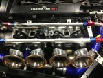
Duratec Engine is fitted, MS2 Extra V3 is assembled and tested, engine running, car now built. IVA passed 26/02/2016
http://www.triangleltd.com
|
|
|
djtom
|
| posted on 1/6/10 at 09:30 AM |
|
|
The GTS axle uses tubing which is the same diameter as scaffolding bar. I don't have it to hand but it's probably 2" od.
This was useful as I chopped the middle out of mine and replaced the section with a straight bit of scaff bar. This was partly because I didn't
like the design (the joint in the middle worried me, especially as a couple have snapped here) and partly because it fouled on the petrol tank in my
car.
Judging from the weight of the tubing it should be strong enough - it's about 3.5mm wall thickness, you just need to ensure you get good
penetration when welding it.
Tom
|
|
|
MikeRJ
|
| posted on 1/6/10 at 09:52 AM |
|
|
Put it this way, the stiffness increases with the 4th power of the diameter, but is only proportional to wall thickness. If you want light and
stiff then you need large diameter tube. Has to be a good reason that the other designs follow this principal.
[Edited on 1/6/10 by MikeRJ]
|
|
|
Minicooper
|
| posted on 1/6/10 at 10:56 AM |
|
|
I used 60mm as this is what the steel stockist had in stock at the time, I also have 50mm od bits and it certainly looks as though it would be strong
enough.
I suppose it also to a lesser extent depends on material quality, my 60mm od is 3mm wall thickness ERW and the 50mm od is also 3mm but CDS steel which
is stronger, so maybe they are similiar in strength I wouldn't know how to work that out though
Cheers
David
|
|
|
craig1410
|
| posted on 1/6/10 at 11:09 AM |
|
|
Are you talking about the main de-dion tube or are you talking about the tubes through which the driveshafts pass? I think you are talking about the
latter aren't you?
In any case, I have this design of axle on my car which I built myself from laser cut parts and I would say that it is very important that trailing
arms are parallel. This means that your chassis mounts must be the same distance apart as the axle mounts. The actual distance doesn't matter so
much as long as they are the same. You also need exactly equal length trailing arms to avoid any axle wrist or binding.
You should also aim to have the trailing arms sloping upwards from chassis to axle very slightly when at standard ride height to aid rear end
stability mid corner. This is due to the fact that the wheelbase changes as the angle of the trailing arm moves away from parallel to the road. If you
have the arms slsoping upwards as described then the outboard wheelbase will shorten when cornering and the inboard wheelbase will lengthen slightly.
This will give you slight rear wheel steering in the direction which will control oversteer. If you had the arms sloping down from chassis to axle
then you would get rear wheel steering which would induce excessive oversteer. I got this tip from Des Hamill's book on suspension design.
I'd stick with the standard axle design and design chassis mounts to suit, even if that means modifying the chassis. You might have trouble
getting your driveshafts through the hole and/or have design strength issues otherwise.
Hth,
Craig.
[Edited on 1/6/2010 by craig1410]
|
|
|