DIY Si
|
| posted on 31/12/10 at 10:23 AM |

|
|
De-dion linkages idea
Morning all.
I've been having a think about the design for the de-dion back end I'm looking at fitting to my Sprite. Since the Sprite normally runs on
cart springs, I have helpfully placed mounting points either side of the were the hub plate/tubes will be for the de-dion. What I had in mind was
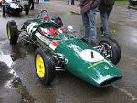
using Watt's linkages either side to deal with axle location in a similar way to how Caterham do it on their de-dion cars. A bit like this:

The only thought I've been having is whether the axle will now be free to rotate about the pivot point. I know that Caterham use the lower A
frame for lateral location, but does is serve a secondary role in preventing the axle rotating, or am I being overly worried? I was hoping to have
another Watt's, or maybe Mumford, link to deal with the lateral location, and I think either would resist the twisting force, but it's not
what they're there for. It would a simple thing to switch to the Caterham A frame design if it would be better over all though.
I'd rather not using twin trailing arms if I can help it, as it would mean cutting the rear bulkhead, which I don't want to do if I can
help it.
Any thoughts at all guys and girls?
Let your plans be dark and as impenetratable as night, and when you move, fall like a thunderbolt.
Sun Tzu, The Art of War
My new blog: http://spritecave.blogspot.co.uk/
|
|
|
|
|
MakeEverything
|
| posted on 31/12/10 at 10:38 AM |
|
|
Youll still need a panhard rod to prevent lateral movement and twisting of the axle.
Kindest Regards,
Richard.
...You can make it foolProof, but youll never make it Idiot Proof!...
|
|
|
DIY Si
|
| posted on 31/12/10 at 10:43 AM |
|
|
I'm hoping to have another Watt's, or maybe Mumford, link to deal with the lateral location.
Let your plans be dark and as impenetratable as night, and when you move, fall like a thunderbolt.
Sun Tzu, The Art of War
My new blog: http://spritecave.blogspot.co.uk/
|
|
|
Sam_68
|
| posted on 31/12/10 at 10:46 AM |
|
|
Why not use the longitudinal Watts link arrangement used by the Lotus Seven S4 and the live axle Sylva Striker, where you have the trailing and
leading arms above and bleow the axle tube, and the brackets welded to the axle form the vertical link?
This torsionally loads the axle beam in roll, so yo need to either provide a rotational joint on the axle, or (as Sylva and Lotus) use compliant
rubber bushes, but it's simple and it's been proven to work well in practice.
If you're clever, you can also use this arrangement with asymmetric linkages to give a degree of roll understeer.
|
|
|
DIY Si
|
| posted on 31/12/10 at 10:55 AM |
|
|
The problem with doing that, and I have thought about it, is that the arms would probably need to be bent to make it work due to where the chassis
mounting points are. Although, the front one will be bolted to the old spring hanger so it could be made a different shape to move the location
point up above the axle line.
Let your plans be dark and as impenetratable as night, and when you move, fall like a thunderbolt.
Sun Tzu, The Art of War
My new blog: http://spritecave.blogspot.co.uk/
|
|
|
blakep82
|
| posted on 31/12/10 at 11:12 AM |
|
|
with how you don't have the arms parallel (thats how it looks in the photo anyway) and using the axle as the centre pivot in a normal watts
link, the axle tube will pivot and rotate in the middle, only a little bit i think, but the bars not being parallel will make that worse. this then
will give you problems on your watts link to stop sideways movement, as your axle tube will be rotating away from it all the time. thats if i've
understood it all correctly
i don't think it will work very well.
also, bending the arms won't make a different. the important bits in suspension is the ball joints on a normal set up. how they join up
doesn't matter. the bars could be bent to a huge S shape bigger than the car, but the movement and affect will still be the same
[Edited on 31/12/10 by blakep82]
________________________
IVA manual link http://www.businesslink.gov.uk/bdotg/action/detail?type=RESOURCES&itemId=1081997083
don't write OT on a new thread title, you're creating the topic, everything you write is very much ON topic!
|
|
|
Sam_68
|
| posted on 31/12/10 at 11:18 AM |
|
|
quote:
Originally posted by DIY Si
The problem with doing that, and I have thought about it, is that the arms would probably need to be bent to make it work due to where the chassis
mounting points are.
Difficult to know without seeing drawings of your actual arrangement, but remember that the 'vertical' links in the Watts (ie. the axle
brackets) don't necessarily have to be vertical, so you might be able to incline the various links so that they give the necessary
clearance through the working range of the axle movement.
|
|
|
mackei23b
|
| posted on 31/12/10 at 11:21 AM |
|
|
Hi There
I've got an S3 Caterham with DeDion.
The Watts linkage is an option, many Caterham's just have one upper radius arm, (like mine), though I think I may upgrade to the Watts linkage
as shown in the pic.
The A frame 'replaces' the panhard rod and lower radius arms as used in a conventional 5 link set up.
In the set up shown, only the A Frame and Watts Link are required to locate the DeDion axle.
I hope this helps?
Cheers
Ian
[Edited on 31/12/10 by mackei23b]
[Edited on 31/12/10 by mackei23b]
|
|
|
DIY Si
|
| posted on 31/12/10 at 11:29 AM |
|
|
Blake,
The pic shows the Caterham set up at full droop, if not past it, as the tube is sitting on the lower chassis rail. I'm not sure how different it
looks at ride height.
The lateral Watt's link would probably be rose jointed, so the movement within the joints should allow for a certain amount of misalignment.
Whether it would be enough or not, I don't know. As you say though, I'd rather not having the twisting force imposed on the de-dion tube,
but removing it through a pivot might then allow the tube to rotate. If that's not really a problem, then I'm ok to go ahead as planned
and using a triple Watt's link set up. Which, if I design it right should pretty much eliminate any unwanted axle movements and restrict it to
near pure vertical movement only.
Sam,
Chances are that the links will be all over the place angle wise to clear the de-dion tube. They may even have to be under the axle, but until I get
round to doing a proper design, rather than back of an envelope type, I won't know for sure.
Mackie,
When you upgrade a Cat to the Watt's link, does the A frame change at all? I'm not sure if it stops the axle twisting round or not. The
only thing I can think of is that with the Watt's link, the lower A frame now enforces a twist on the de-dion tube as it moves up and down due
to moving in an arc whilst the Watt's should be a straight line.
Let your plans be dark and as impenetratable as night, and when you move, fall like a thunderbolt.
Sun Tzu, The Art of War
My new blog: http://spritecave.blogspot.co.uk/
|
|
|
Sam_68
|
| posted on 31/12/10 at 11:38 AM |
|
|
quote:
Originally posted by mackei23b
...many Caterham's just have one upper radius arm, (like mine), though I think I may upgrade to the Watts linkage as shown in the pic.
The A frame 'replaces' the panhard rod and lower radius arms as used in a conventional 5 link set up.
The problem with this is that under braking loads (in particular) the forces are trying to bend the axle beam backwards between the outer upper
(trailing arm) and central lower (A-frame) locating points.
How much of a problem this is in practice obviously depends on how much grip you have...
[Edited on 2/1/11 by Sam_68]
|
|
|
Sam_68
|
| posted on 31/12/10 at 11:47 AM |
|
|
quote:
...the lower A frame now enforces a twist on the de-dion tube as it moves up and down due to moving in an arc whilst the Watt's should be
a straight line.
Again, if you're clever enough to make the Watts asymmetrical, it doesn't have to follow a straight line or, indeed, a vertical
straight line. 
...which means that under bump loads (you're not worried about droop, 'cos the worst that can happen is that the axle has to carry the
unsprung weight), you can make the line of the Watts movement follow the approximation of the arc of the A-frame closely enough for it to be pretty
much irrelevant.
[Edited on 31/12/10 by Sam_68]
|
|
|
britishtrident
|
| posted on 31/12/10 at 12:09 PM |
|
|
That arrangement is best used only with a de ion tube not a live axle ---- in fact it is really only ideal for a De Dion with inboard brakes.
[I] What use our work, Bennet, if we cannot care for those we love? .
― From BBC TV/Amazon's Ripper Street.
[/I]
|
|
|
mackei23b
|
| posted on 31/12/10 at 01:44 PM |
|
|
The Watts link is a straight swap for the upper radius arm, the A-frame stays the same.
Cheers
Ian
quote:
Originally posted by DIY Si
Blake,
The pic shows the Caterham set up at full droop, if not past it, as the tube is sitting on the lower chassis rail. I'm not sure how different it
looks at ride height.
The lateral Watt's link would probably be rose jointed, so the movement within the joints should allow for a certain amount of misalignment.
Whether it would be enough or not, I don't know. As you say though, I'd rather not having the twisting force imposed on the de-dion tube,
but removing it through a pivot might then allow the tube to rotate. If that's not really a problem, then I'm ok to go ahead as planned
and using a triple Watt's link set up. Which, if I design it right should pretty much eliminate any unwanted axle movements and restrict it to
near pure vertical movement only.
Sam,
Chances are that the links will be all over the place angle wise to clear the de-dion tube. They may even have to be under the axle, but until I get
round to doing a proper design, rather than back of an envelope type, I won't know for sure.
Mackie,
When you upgrade a Cat to the Watt's link, does the A frame change at all? I'm not sure if it stops the axle twisting round or not. The
only thing I can think of is that with the Watt's link, the lower A frame now enforces a twist on the de-dion tube as it moves up and down due
to moving in an arc whilst the Watt's should be a straight line.
|
|
|
DIY Si
|
| posted on 1/1/11 at 10:38 AM |
|
|
So, over all then, no-one can see anything major that would stop this working as an idea?
I will make a model of it all before I move onto making the real thing so that should show up anything I've over looked.
Thanks for your help, and if there's anything else that you can think of, please let me know!
Let your plans be dark and as impenetratable as night, and when you move, fall like a thunderbolt.
Sun Tzu, The Art of War
My new blog: http://spritecave.blogspot.co.uk/
|
|
|
MikeR
|
| posted on 1/1/11 at 02:07 PM |
|
|
How are you going to stop the diff nose moving upwards / downwards if you don't fit some form of trailing / leading arm?
(read this thread yesterday from my mobile and couldn't figure it then, headache now is stopping me from grasping it)
|
|
|
Sam_68
|
| posted on 1/1/11 at 04:01 PM |
|
|
quote:
Originally posted by DIY Si
So, over all then, no-one can see anything major that would stop this working as an idea?
Just to be clear, you are talking about a De Dion arrangement, aren't you? Not that it makes a whole lot of difference...
MikeR's post is a little confusing, 'cos it's talking about diff noses moving when the diff on a de Dion will be mounted to the
chassis, but his fundamental point is correct and reflects what you've already identified in your first post: without the A-frame (or a pair of
trailing arms) below the axle, the axle tube is free to swing backwards and forwards underneath the Watts links.
In other words, to directly respond to the question you posed in your original post: yes , the A-frame on the Caterham does play a secondary
roll in preventing the axle rotating, so no, the Caterham Watts link arrangement won't work without it (or an equivalent pair of trailing
arms) below the axle.
[Edited on 1/1/11 by Sam_68]
|
|
|
DIY Si
|
| posted on 1/1/11 at 06:12 PM |
|
|
Yup, the clues in the title! De-dion set up for the back of a AH Sprite.
So what are folk's opinion's on whether a lateral Watt's linkage is capable of resisting the rotating motion of the axle? If not,
then I may well bin that idea in favour of the A frame that Caterham use. That might even be easier to do as well, as I could make the front springs
mounts bigger so they double up for both mountings.
PS, Sam-68, are you the same Sam with the FW400 from the kit car section on PH?
Let your plans be dark and as impenetratable as night, and when you move, fall like a thunderbolt.
Sun Tzu, The Art of War
My new blog: http://spritecave.blogspot.co.uk/
|
|
|
britishtrident
|
| posted on 1/1/11 at 06:40 PM |
|
|
quote:
Originally posted by DIY Si
So, over all then, no-one can see anything major that would stop this working as an idea?
I will make a model of it all before I move onto making the real thing so that should show up anything I've over looked.
Thanks for your help, and if there's anything else that you can think of, please let me know!
It will only work on a live axle for very limited suspension travel (as on Lotus Seven S4) .
Strange things happen to the prop shaft UJ angles on bump and droop.
[I] What use our work, Bennet, if we cannot care for those we love? .
― From BBC TV/Amazon's Ripper Street.
[/I]
|
|
|
Sam_68
|
| posted on 1/1/11 at 07:10 PM |
|
|
quote:
Originally posted by DIY SiPS, Sam-68, are you the same Sam with the FW400 from the kit car section on PH?
Yep. Guilty as charged.
|
|
|
Sam_68
|
| posted on 1/1/11 at 07:36 PM |
|
|
quote:
Originally posted by britishtridentIt will only work on a live axle for very limited suspension travel (as on Lotus Seven S4) .
Just to be clear: the Watts link arrangement on the Caterham, shown at the top of the thread, works quite differently to the longitudinal Watts links
on a Seven S4 or a Sylva.
FWIIW, the Sylva and the S4 don't have that limited a suspension travel: I have my Sylva set up quite soft, by the standards of silly
lightweight sportscars, and it still works just fine.... you just need to make sure you have enough longitudinal compliance in the bushes (and the
geometry is such that it doesn't take much). You've got to realise that the S4/Sylva arrangement looks like a Watts linkage, but it
works more by compressing the sidewalls of the bushes than it does by rotating the vertical link in the geometrically classical manner of a Watts
linkage. Quite apart from anything else, if you got rid of all the compliance by fitting super-accurate Rose joints in place of the bushes so that it
acted like a proper Watts link, you'd end up with the World's Biggest anti-roll bar! 
|
|
|
MikeR
|
| posted on 1/1/11 at 08:13 PM |
|
|
quote:
Originally posted by MikeR
How are you going to stop the diff nose moving upwards / downwards if you don't fit some form of trailing / leading arm?
(read this thread yesterday from my mobile and couldn't figure it then, headache now is stopping me from grasping it)
Sorry guys - headache and reading on new years eve means i forgot early on it was de-dion.
Now i grasp its de-dion, don't you risk introducing a (large) twisting load into the de-dion axle if you go through a one wheel bump? Its going
to rotate that side of the axle by the amount of bump + multiplied by the distance the de-dion axle is from the centre of the watts link (although on
the bright side, you could say its a huge anti roll bar).
|
|
|
DIY Si
|
| posted on 2/1/11 at 10:51 AM |
|
|
Ok then, sounds like I might be better off with a Caterham style A frame lower link than a Watt's link for lateral location. It might even make
a few things slightly easier, as although it will introduce an arc to things, as Sam said, I can make the longitudinal Watt's links move in a
very similar way to get a near straight movement. This would then allow me to have the coil overs slightly off vertical, which would help with the
limited room I have too.
It'll also be easier to make too. And possibly a bit cheaper.
Let your plans be dark and as impenetratable as night, and when you move, fall like a thunderbolt.
Sun Tzu, The Art of War
My new blog: http://spritecave.blogspot.co.uk/
|
|
|
Sam_68
|
| posted on 2/1/11 at 10:57 AM |
|
|
quote:
Originally posted by MikeR
Now i grasp its de-dion, don't you risk introducing a (large) twisting load into the de-dion axle if you go through a one wheel bump? Its going
to rotate that side of the axle by the amount of bump + multiplied by the distance the de-dion axle is from the centre of the watts link (although on
the bright side, you could say its a huge anti roll bar).
No; see my post immediately above.
The Caterham linkage has a proper pivot point in the centre of the vertical link (where it attaches to the axle), so it doesn't try to
twist the axle. It simply replaces the upper radius rods, though - it still relies on the A-frame below the axle to stop the axle swinging fore
and aft like a pendulum below the upper (Watts) locations. Its main advantage is that it minimises the roll steer you encounter with the normal, short
upper radius arms on the Caterham (the fact that the A-frame still follows a fairly short arc is less important, because in in roll - ie. cornering -
there isn't much vertical movement of the centre location of the A-frame to the de Dion relative to the sprung mass).
The Seven S4/Sylva arrangement (where the vertical link is just a 'bar', welded rigidly to the axle with no rotating pivot point in
the middle) would induce the axle twist you refer to, if you used Rose joints (and there have been people daft enough to try....), but if you
use the correct rubber bushes it absorbs the necessary movement through sidewall compression of the bushes, in practice.
As I understand it, the DIY Si thinks that this will be unsuitable/inconvenient for his installation, though, as he was hoping to use the mounting
points for the previous leaf springs, which will be located in a pretty much horizontal line above the axle?
It might be possible to use the Sylva/S4 arrangement by utilising the rear leaf spring mounting as the upper (leading) arm and fabricating a new
mounting bracket down near the rear bulkhead/floor pan intersection to take the lower (trailing) arm, but I'm not familiar enough with the
Spridget to know how practical/possible this would be without taking a proper look and doing some drawings.
|
|
|
DIY Si
|
| posted on 2/1/11 at 11:30 AM |
|
|
Nearly right Sam. The mounts will be in a near horizontal line inline with the axle, if not under it in bump.
And due to the way a Sprite is built, the rear spring mounts aren't as strong as the front ones. Due to being a tiny two seater, the rear
bulkhead sits just behind the seats and has the front spring mounts in it's base. The rear mounts aren't as strong as they hang out from
the boot floor, with just a simple chassis leg for support. Because of this, I don't want to impart any twist down the longitudinal arms if I
can help it, so that counts the S4/Sylva stuff out really.
Using the Caterham Watt's link will, as Sam says pretty much remove/restrict the roll steer with out introducing any unwanted forces into the
mounts. So it seems that this may well be the way to go.
Oh, whilst I'm not sure if it will make any difference, total suspension travel is likely to be 5", possibly a little less.
Let your plans be dark and as impenetratable as night, and when you move, fall like a thunderbolt.
Sun Tzu, The Art of War
My new blog: http://spritecave.blogspot.co.uk/
|
|
|
Sam_68
|
| posted on 2/1/11 at 12:50 PM |
|
|
I'm still not sure I'd rule out the Sylva/S4 solution so quickly, if I were in your position.
The Caterham linkage still requires an A-frame or lower trailing arms to complete the longitudinal location, is much more complex (hence more costly
and heavier; certainly in terms of unsprung weight and probably in terms of overall weight, even allowing for beefing up of the rear chassis pickups),
and doesn't restrain the axle as well against heavy braking loads. The extra accuracy afforded by the ability to fully Rose joint it is offset
by the fact that the dimensions of the vertical link on the bellcrank need to be so compact that even the tiniest amount of play or flex is magnified
geometrically (and there are more joints for the play to occur in...).
The Sylva/S4 solution works at least as well in practice and has the additional advantage that it's very easy to adjust the asymmetry of the
Watts links to fine-tune the roll-steer characteristics.
5" total suspension travel certainly isn't a problem: the Sylva certainly has a lot more than that.
|
|
|