Trollyjack
|
| posted on 30/5/11 at 09:41 PM |

|
|
Front Shocker top mount ?
Hi
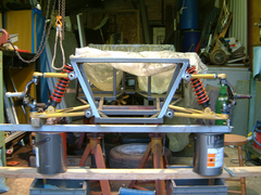
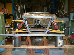
I have assembled the front end to day and now deciding where to put the top shocker mount
Do I put it on the side of the top rail
In both positions I am getting about 40mm of travel on the shocker
 
Or under side of top rail
 
On side of top rail
Been told they are best stood up but please comment
I think under side would be better and more consealed
Comments welcome Please
There are more photos in my photo archive under front end
TrollyJack
|
|
|
|
|
Chippy
|
| posted on 30/5/11 at 10:11 PM |

|
|
I would mount it under the chassis rail for two reasons, 1/ it looks neater, and is better for IVA. 2/ you will get "slightly" more travel
as its on more of an angle. HTH Ray
To make a car go faster, just add lightness. Colin Chapman - OR - fit a bigger engine. Chippy
|
|
|
tilly819
|
| posted on 30/5/11 at 10:22 PM |

|
|
In the ideal world it should be placed were the load path passes through the center of the supporting chassis rail
tilly
F20C Haynes roadster 440 BHP/Tonne www.youtube.com/handmadeextreme
|
|
|
blakep82
|
| posted on 30/5/11 at 10:28 PM |

|
|
quote:
Originally posted by tilly819
In the ideal world it should be placed were the load path passes through the center of the supporting chassis rail
tilly
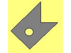
personally i'd have brackets like this
 
Description
with either of your options, you're never applying a sort of compression force, its always trying to push the brackets away from the tube
________________________
IVA manual link http://www.businesslink.gov.uk/bdotg/action/detail?type=RESOURCES&itemId=1081997083
don't write OT on a new thread title, you're creating the topic, everything you write is very much ON topic!
|
|
|
Jon Ison
|
| posted on 30/5/11 at 10:37 PM |

|
|
Mine are as your lower photo but connected to each end of a rail that is welded to the underside of the upper chassis rails, also cross braced to the
bottom rails. Well I know what I mean........
|
|
|
Trollyjack
|
| posted on 30/5/11 at 10:55 PM |

|
|
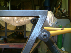
Was thinking of lining the top eye around here and putting a channel across from the outer toprail the the cross support thar is 5" inside.
 
TrollyJack
|
|
|
Peteff
|
| posted on 31/5/11 at 08:36 AM |

|
|
Better on the outside of the rail to keep it more upright. More angle needs stronger springing.
yours, Pete
I went into the RSPCA office the other day. It was so small you could hardly swing a cat in there.
|
|
|
Badger_McLetcher
|
| posted on 31/5/11 at 12:30 PM |

|
|
IIRC if you place them on the inside of the chassis you'll get a more pronounced spring fall off rate- the more vertical the better.
|
|
|
Doctor Derek Doctors
|
| posted on 31/5/11 at 12:42 PM |

|
|
Instead of just guessing you should sketch it up and check the installation ratio / suspension rate, really you want it to have a constant or
'rising rate'.
I.E for every 1mm of the wheel the shock compresses by Xmm, ideally with X being constant or increasing for each consequtive mm of wheel movement.
If you don't check and have X decreasing for each mm of wheel travel then you will end up with some very odd handling, especially in roll.
This is very basic input though.
Is this position not defined in 'the' book?
[Edited on 31/5/11 by Doctor Derek Doctors]
|
NOTE:This user is registered as a LocostBuilders trader and may offer commercial services to other users
|
Trollyjack
|
| posted on 1/6/11 at 10:31 AM |

|
|
Looked in Book and it does not say where to mount the top mounting brackets
some pictures show on side of top rail and some photos show it under side of top rail ??
TrollyJack
|
|
|
Doctor Derek Doctors
|
| posted on 1/6/11 at 12:48 PM |

|
|
quote:
Originally posted by Trollyjack
Looked in Book and it does not say where to mount the top mounting brackets
some pictures show on side of top rail and some photos show it under side of top rail ??
If you get me the following dims I can sketch it up for you in CAD:
Length of lower wishbone pick-up to lower shock mount
Angle between the line (between the above two points) and the horizontal Plane (floor)
The distance between the lower wishbone mount and the center of the chassis top rail.
Angle between the line (between the above two points) and the horizontal plane (floor)
Open and closed length of the shock
Overall length of the lower wishbone.
A simple sketch that I have knocked up will tell you the installation ratio in seconds and also if you have rising/falling/constant rate in various
positions and then you can make an informed decision.
|
NOTE:This user is registered as a LocostBuilders trader and may offer commercial services to other users
|
Trollyjack
|
| posted on 1/6/11 at 03:27 PM |

|
|
Thats Brill
I'll measure next time i'm at my lock up
Kev
TrollyJack
|
|
|
Bare
|
| posted on 1/6/11 at 04:56 PM |

|
|
Simply Try to mount the shocker unit as vertically as absolutely possible. ..
Save yourself a maths exercise to tell you exactly that .
Wouldn't overly worry about structural 'niceities' as even the suspension pickup points on these Locost chassis are just daft/poor
. The mount ears have been documented to fatigue off due to their poor placement and inadequate support.
Shock mount 'strength' is the least of your worries.
[Edited on 1/6/11 by Bare]
|
|
|
Trollyjack
|
| posted on 1/6/11 at 09:08 PM |

|
|
to Doctor Derek Doctors
Length of lower wishbone pick-up to lower shock mount = 225mm
Angle between the line (between the above two points) and the horizontal Plane (floor) = 0°
The distance between the lower wishbone mount and the center of the chassis top rail. = 270mm
Angle between the line (between the above two points) and the horizontal plane (floor) = 74°
Open and closed length of the shock = 320mm open 255mm closed with rubber bump stop 235mm with out
Overall length of the lower wishbone. 340mm to centre od bottom ball joint.
I have drawn it up on a cad package but not ver good at it yet I can email you the DFX file if you wish
TrollyJack
|
|
|
Doctor Derek Doctors
|
| posted on 2/6/11 at 09:32 AM |

|
|
quote:
Originally posted by Trollyjack
Length of lower wishbone pick-up to lower shock mount = 225mm
Angle between the line (between the above two points) and the horizontal Plane (floor) = 0°
The distance between the lower wishbone mount and the center of the chassis top rail. = 270mm
Angle between the line (between the above two points) and the horizontal plane (floor) = 74°
Open and closed length of the shock = 320mm open 255mm closed with rubber bump stop 235mm with out
Overall length of the lower wishbone. 340mm to centre od bottom ball joint.
I have drawn it up on a cad package but not ver good at it yet I can email you the DFX file if you wish
I made a sketch yesterday, I'll stick the numbers in at lunchtime and test some positions.
I will test for Inside, Outside and Below the rail and tell you the rate, and rate change.
|
NOTE:This user is registered as a LocostBuilders trader and may offer commercial services to other users
|
paulf
|
| posted on 2/6/11 at 09:48 AM |

|
|
I had the same dilemma when i built mine and remember something about the mounting bolt being hard to fit when under the chassis rail as it was tight
to the Fu tubes.I fitted the brackets to the outside of the chassis rail and made a wedge section that fitted between the rail and bracket to make it
parallel to the lower mounting bracket .I thought the shock being more upright was the best way to have it and as mentioned the spring rate can be
lower and wont tend to end up as a falling rate as could happen if mounted under the rail and to far in board.
Paul
|
|
|
Doctor Derek Doctors
|
| posted on 2/6/11 at 02:15 PM |

|
|
Right then.
With those dims you cant put the shock directly inline with the chassis rail as you will have a very high ride height or your shock will be nearly
fully compressed to keep that angle of the wishbone.
I have made an assumption that the centre of the shock top mount will be 40mm away from the centre of the chassis top rail (to give clearance) and
that you will have 30-35mm of droop and 60-65mm of bump.
Inside mount:
-30 = 312.783
-20 = 307.713 = 5.07
-10 = 302.579 = 5.134 = 0.064
0 = 297.38 = 5.199 = 0.065
10 = 292.118 = 5.262 = 0.063
20 = 286.792 = 5.326 = 0.064
30 = 281.402 = 5.39 = 0.064
40 = 275.947 = 5.455 = 0.065
50 = 270.429 = 5.518 = 0.063
60 = 264.846 = 5.583 = 0.065
Outside Mount:
-30 = 315.486
-20 = 309.505 = 5.918
-10 = 303.469 = 6.036 = 0.118
0 = 297.38 = 6.089 = 0.053
10 = 291.328 = 6.052 = -0.037
20 = 285.044 = 6.284 = 0.232
30 = 278.798 = 6.246 = -0.038
40 = 272.502 = 6.296 = 0.05
50 = 266.157 = 6.345 = 0.049
60 = 259.762 = 6.395 = 0.05
The first number is the suspension travel (- = droop, + = Bump) The second number is the shock length, the third number is the change in shock length
and the forth number is the change in shock rate.
In my conclusion mounting inside will give roughly a 5:10 installation ratio, mounting outside will give a 6:10 installation ratio thus outside would
be stiffer with the same springs.
What's interesting as that mounting inside gives a lovely constant (amazingly constant) figure for the rate increase (0.063-0.065mm) over the
entire travel of the shock which is ideal, whereas the outside mounted shock has a very erratic change of rate (-0.037-0.232mm) which will give odd
handling.
If it was my car I would mount the shock inside to give more constant and progressive damper/spring travel with a constant rate increase, it will also
allow you to have a longer wheel travel (also more ride height adjustment) and it will be a much neater finish to the car.
Hope that helps.
|
NOTE:This user is registered as a LocostBuilders trader and may offer commercial services to other users
|
Trollyjack
|
| posted on 2/6/11 at 07:21 PM |

|
|
So are you saying that the top mount is to be inside the top rail
where exactly is it to be, on the centre line of the top rail or under neath ?
could you you email me a sketch Please
TrollyJack
|
|
|
Doctor Derek Doctors
|
| posted on 3/6/11 at 07:20 AM |

|
|
quote:
Originally posted by Trollyjack
So are you saying that the top mount is to be inside the top rail
where exactly is it to be, on the centre line of the top rail or under neath ?
could you you email me a sketch Please
I have screen grabbed the sketch, here and in my archive
Basically though if you keep the wishbone inner pivot to - lower shock mount line at 0° (as you specified), extend to the shock to 295-300mm (297.38mm
in the sketch) and then put the top mount so it sits 40mm from the centreline of the top rail you'll have what I used.
The two double white circles are the top and bottom shock mounts, the 25x25mm square box is obviously the chassis top rail and I I'm sure you
can work out the rest.
 
|
NOTE:This user is registered as a LocostBuilders trader and may offer commercial services to other users
|
Trollyjack
|
| posted on 3/6/11 at 08:50 AM |

|
|
Thats brilliant thanks very much for you time, it has been much appreciated
By luck my idear was not too far away
 
now to manufacture the top bracket I intent to make this out of Stainless to give it better strength.
TrollyJack
|
|
|
Doctor Derek Doctors
|
| posted on 3/6/11 at 09:30 AM |

|
|
No Probs mate, I tried to base it on your initial projections to make something manufacturable.
Have fun building, I wish I could get some time to do some practical work rather than being in front of the desk.
|
NOTE:This user is registered as a LocostBuilders trader and may offer commercial services to other users
|
Doctor Derek Doctors
|
| posted on 3/6/11 at 09:35 AM |

|
|
quote:
Originally posted by Bare
Simply Try to mount the shocker unit as vertically as absolutely possible. ..
Save yourself a maths exercise to tell you exactly that
....or spend 30 mins doing some maths and find out that doing that would have given poor, inconsistent geometry.
[Edited on 3/6/11 by Doctor Derek Doctors]
Designer and Supplier of the T89 Designs - Single Seater Locost. Build you own Single Seater Racecar for ~£5k.
Plans and Drawings available, U2U or e-mail for details.
Available Now: The Sports Racer Add-On pack, Build a full bodied Sports Racer for Trackdays, Sprints and Racing.

www.t89.co.uk
www.racecarwings.co.uk
callan@t89.co.uk
|
NOTE:This user is registered as a LocostBuilders trader and may offer commercial services to other users
|
Neville Jones
|
| posted on 3/6/11 at 10:00 AM |

|
|
quote:
Originally posted by Bare
Simply Try to mount the shocker unit as vertically as absolutely possible. ..
Save yourself a maths exercise to tell you exactly that .
Wouldn't overly worry about structural 'niceities' as even the suspension pickup points on these Locost chassis are just daft/poor
. The mount ears have been documented to fatigue off due to their poor placement and inadequate support.
Shock mount 'strength' is the least of your worries.
[Edited on 1/6/11 by Bare]
That statement above is about right on every count. What oriface DDD pulls his info from I don't know,( Wikipedia?or the same place as the
ship's engineers?) but as the shock inclines from the vertical, once you get past about 10 degrees, things start to go way past non linear in
the non desireable direction.
The locost setup puts some limits with the top wishbone design, and clearance for the coilover setup.
There are other ways of mounting the top shock bolt. I'll try and post a pic.
And yes, accepted practice among knowledgeable suspension designers would be to mount the shock as close to vertical as possible, with enough inward
inclination to give a rising rate up to the point of max bump, where the shock would be 90 degrees to the wishbone.
Well, that's how the couple of designers I've met would do it.
Cheers,
Nev.
|
|
|
flak monkey
|
| posted on 3/6/11 at 10:11 AM |

|
|
quote:
Originally posted by Neville Jones
quote:
Originally posted by Bare
Simply Try to mount the shocker unit as vertically as absolutely possible. ..
Save yourself a maths exercise to tell you exactly that .
Wouldn't overly worry about structural 'niceities' as even the suspension pickup points on these Locost chassis are just daft/poor
. The mount ears have been documented to fatigue off due to their poor placement and inadequate support.
Shock mount 'strength' is the least of your worries.
[Edited on 1/6/11 by Bare]
That statement above is about right on every count. What oriface DDD pulls his info from I don't know,( Wikipedia?or the same place as the
ship's engineers?) but as the shock inclines from the vertical, once you get past about 10 degrees, things start to go way past non linear in
the non desireable direction.
The locost setup puts some limits with the top wishbone design, and clearance for the coilover setup.
There are other ways of mounting the top shock bolt. I'll try and post a pic.
And yes, accepted practice among knowledgeable suspension designers would be to mount the shock as close to vertical as possible, with enough inward
inclination to give a rising rate up to the point of max bump, where the shock would be 90 degrees to the wishbone.
Well, that's how the couple of designers I've met would do it.
Cheers,
Nev.
Absolutely correct 
Sera
http://www.motosera.com
|
|
|
Fred W B
|
| posted on 3/6/11 at 11:11 AM |

|
|
quote:
to manufacture the top bracket I intent to make this out of Stainless to give it better strength.
Please don't make the brackets from stainless unless you intend to use the correct consumable to weld it to carbon steel.
Stainless is alloyed to give certain properties, if you dilute the alloys (by welding to carbon steel) you end up with the wrong structure and form a
brittle rather than ductile weld.
When welding with 316 use 316 electrodes, when welding with 304 use 309 (best) or 316 electrodes.
You would be much better off to make the bracket in thicker carbon steel if you want it stronger.
Cheers
Fred W B.
[Edited on 3/6/11 by Fred W B]
You can do it quickly. You can do it cheap. You can do it right. – Pick any two.
|
|
|


