NigeEss
|
| posted on 21/10/11 at 12:30 AM |

|
|
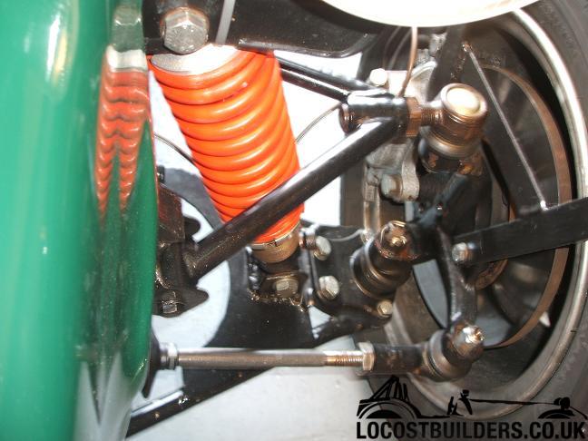
How far in is the transit drag ling screwed ?
Have finally sussed setting up caster and camber but the top balljoint is only in by about 14 turns
(20mm ish) and this concerns me.
A simple solution is to raise the top wishbone mounts an inch or pack them out a bit (not keen)
so what would be the effect of raising the mounts which are currently to the book measurements.
Really don't want to remake the wishbones.
Time is an illusion. Lunchtime doubly so.................Douglas Adams.
|
|
|
|
|
steve m
|
| posted on 21/10/11 at 05:05 AM |

|
|
If its a book built chassis and suspension, why will it be so different?
My top links actually stick thru the inside slightley and have about 40mm thread holding them in (plenty)
|
|
|
907
|
| posted on 21/10/11 at 06:52 AM |

|
|
I think that raising the mounting points will alter the amount of camber change
when the suspension is compressed.
My first set of bones I made to the book.
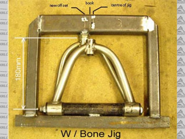
The second set have 22mm of off set (castor) and I also made them a tad wider
as I too was concerned that there was insufficient threads holding the drag link in.
The pic shows a new w/b tacked up in the jig with the old book w/b laying on top.
Unfortunately the camera angle doesn't show this very well.
 
Book w/b on top of modded w/b
Are your M18 threaded bushes long enough to be able to cut out and reposition?
It would save remaking the complete wish bone.
Cheers
Paul G
|
|
|
NigeEss
|
| posted on 21/10/11 at 07:15 AM |

|
|
quote:
Originally posted by steve m
If its a book built chassis and suspension, why will it be so different?
The mounting points are to the sketch in the book but the bones are 50mm wider top and bottom.
The set up sketch in the book indicates they should be parallel to each other but most of what I've
read shows the top bone angled down towards the car, which mine currently are.
Time is an illusion. Lunchtime doubly so.................Douglas Adams.
|
|
|
steve m
|
| posted on 21/10/11 at 07:43 AM |

|
|
The top ones on mine are are parelell to the ground at rest
the bottoms are at an angle of about 15% at rest,
i will post a pic once the car is out of the garage
BTW mine is book built exactley to the first edition book, so possibly is a differnt design?
|
|
|
adithorp
|
| posted on 21/10/11 at 08:03 AM |

|
|
As a min, you want the distance screwed in to be 1+1/2 times the thread diameter. If it was held by a nut the force would be applied to fewer threads
(thickness of the nut) than that so you can expect the threads will hold.
What is more worrying is that the extra length sticking out increases the leverage/bending being applied but they are designed to cope with the loads
applied through a fully (over)loaded Transit (though not in this configuration).
My rear upper mounts are screwed in just over that amount and have held for 13000 miles of abuse, although at some point, I plan to engineer a better
solution.
"A witty saying proves nothing" Voltaire
http://jpsc.org.uk/forum/
|
|
|
steve m
|
| posted on 21/10/11 at 08:27 AM |

|
|
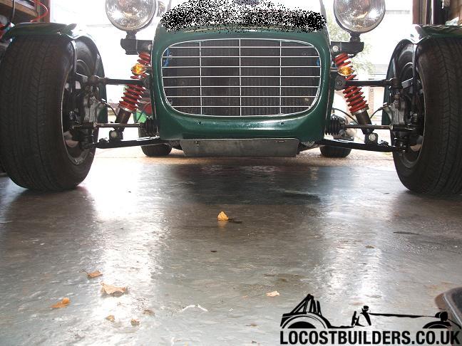
Attached is my front suspension at rest
The upper arms go slightley up say 1-2%
the lower arms drop more 5010% and both are the same amount even though the pics say otherwise!!

The top link, protrudes about 1mm, and is encased in 40mm thread
just for info, are your top links long enough, as i have a total of 67mm of avialaibe thread

regards
steve
|
|
|
stevegough
|
| posted on 21/10/11 at 08:43 AM |

|
|
Steve M - what did you mean by the typo error.....5010% 
Luego Locost C20XE.
Build start: October 6th 2008.
IVA passed Jan 28th 2011.
First drive Feb 10th 2011.
First show: Stoneleigh 1st/2nd May 2011.
'Used up' first engine may 3rd 2011!
Back on the road with 2nd engine may 24th
First PASA mad drive 26/7/11
Sold to Mike in Methyr Tydvil 19/03/14
|
|
|
steve m
|
| posted on 21/10/11 at 09:30 AM |

|
|
Ooops, i meant 5 - 10 degrees!
|
|
|
MikeRJ
|
| posted on 21/10/11 at 10:09 AM |

|
|
quote:
Originally posted by 907
The pic shows a new w/b tacked up in the jig with the old book w/b laying on top.
Unfortunately the camera angle doesn't show this very well.
 
Book w/b on top of modded w/b
How on earth do the wishbones come out of that jig after they are welded? 
|
|
|
907
|
| posted on 21/10/11 at 11:25 AM |

|
|
quote:
Originally posted by MikeRJ
quote:
Originally posted by 907
The pic shows a new w/b tacked up in the jig with the old book w/b laying on top.
Unfortunately the camera angle doesn't show this very well.
 
Book w/b on top of modded w/b
How on earth do the wishbones come out of that jig after they are welded? 
Ready for acid cleaning and polishing. 
Cheers,
Paul G
|
|
|


