derf
|
| posted on 21/10/05 at 04:08 AM |

|
|
New A arms (pics)
The jig was good enough that the lower arm can be fliped over and fit in either way. The 2 uppers are exactly alike. I fishmouthed all the tubes with
my handy dandy trusty angle grinder, lots of fitting and a little bit of trial and error. I did screw up my first try at a lower arm (not
pictured).
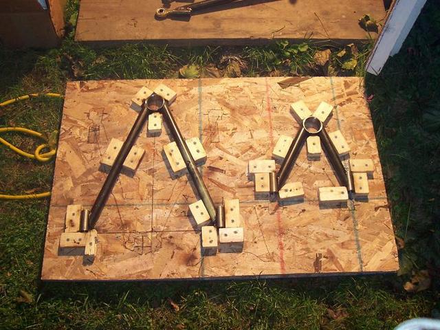
These are built around using s10 steering knuckles, and this design is adjustable for camber, and caster. Toe will be adjustable with the steering
rack.
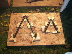 
before welding in the jig
before and after in jig
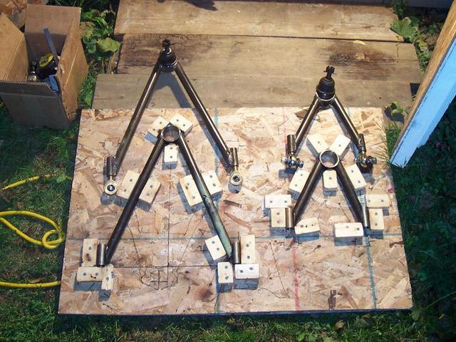
with and without hardware
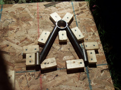 
a closer view of the upper arm jig
 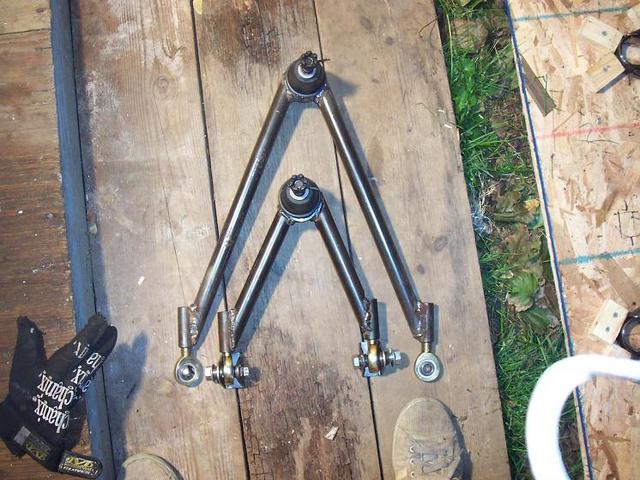
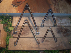
size difference between upper and lower
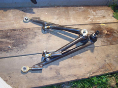 
upper and lower together
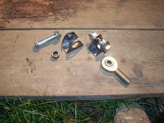 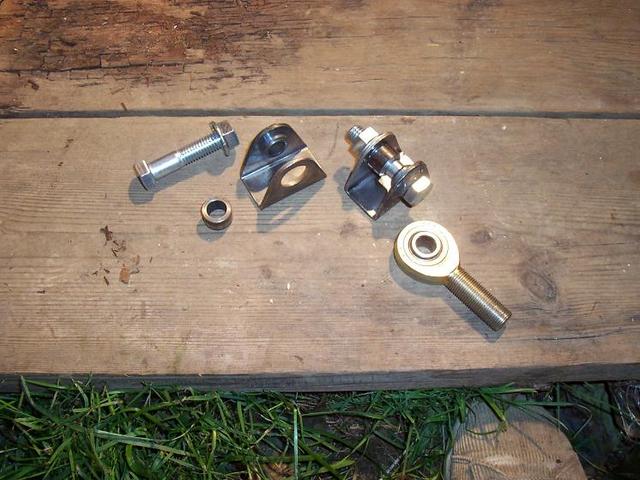
The brackets clamp around the heim joint
|
|
|
|
|
chrisf
|
| posted on 21/10/05 at 10:15 AM |
|
|
Looks good. I'd put a horizontal brace between the two treaded tubes. As-is, there isn't a lot of welded area for you to trust your life
to.
I've always wondered...On these types of set ups, what keeps the ball joint from dropping through the bottom or lifting ou the top? Is the a
snap ring or something?
|
|
|
Avoneer
|
| posted on 21/10/05 at 11:08 AM |
|
|
They look really nice.
Like chris said, I would weld another round bar across the two arms of the lower bone nearer the rose jointed end.
Pat...
No trees were killed in the sending of this message.
However a large number of electrons were terribly inconvenienced.
|
|
|
derf
|
| posted on 21/10/05 at 12:55 PM |
|
|
that was the plan, I also need to cut up some a bracket for the shocks to mount on.
|
|
|
MikeRJ
|
| posted on 21/10/05 at 01:37 PM |
|
|
quote:
Originally posted by chrisf
Looks good. I'd put a horizontal brace between the two treaded tubes.
What would this actually do? Is it simply to ensure that shear loads are equaly shared by the two rod ends?
|
|
|
chrisf
|
| posted on 21/10/05 at 11:09 PM |
|
|
Derf will tell you. As his control arms stand, he can flex them about. Adding the horizontal bar will stiffen it up quite a bit. Of course they will
be stiffer once mounted on the chassis, but why take chances.
--Chris
|
|
|
derf
|
| posted on 22/10/05 at 12:23 AM |
|
|
no they don't move at all, but a horizontal bar will definatly create a much stronger unit.
|
|
|
britishtrident
|
| posted on 22/10/05 at 10:47 AM |
|
|
Look just dandy to me , I was at one stage toying with something similar using Mini/Metro ball joints.
|
|
|


%20(WinCE).JPG)