ed_crouch
|
| posted on 11/3/06 at 01:39 AM |

|
|
Unequal trailing arms for DeDion Anti-roll
Has anyone played with unequal length trailing arms for the rear suspension of a DeDion car??
What'll hapen is that under cornering, one side of the car will drop more than the other, and the unequal length arms will cause one hub to
rotate (about the driveshaft axis) by more than the other, putting the (DeDion) beam into torsion.
I realise the dangers if it is done badly (torsional rupture, crash), but if analysed and designed well, this would give a wicked anti-roll system for
the rear suspension, for naff all extra weight and no more parts.
Anyone played with this??
Ed.
[Edited on 11/3/06 by ed_crouch]
I-iii-iii-iii-ts ME!
Hurrah.
www.wings-and-wheels.net
|
|
|
|
|
MikeRJ
|
| posted on 11/3/06 at 08:40 AM |
|
|
Designing in geometry that deliberately causes binding dosen't sound good to me, the forces imposed on the bushes and brackets will be
horrendous.
|
|
|
blueshift
|
| posted on 11/3/06 at 11:07 AM |
|
|
sounds like a bad idea to me. the bar has to be proper stiff to keep the steering geometry, I think other things like your arms and brackets are going
to give way first.
I had thought a bit about dedion with a hub (or hubs) that were allowed to rotate around the bar, so that geometry could be changed in bump/droop.
tricky though.
|
|
|
Volvorsport
|
| posted on 11/3/06 at 11:37 AM |
|
|
in theory , even with equal length arms , youll get some form of rear steer .
you would need more twist/rotation for it to work as an anti roll bar for the full range of suspension movement .
www.dbsmotorsport.co.uk
getting dirty under a bus
|
|
|
britishtrident
|
| posted on 11/3/06 at 03:33 PM |
|
|
Lotus did it with the live axle on the Seven S4 --- took the form of a watts linkage --- places very high loads on chassis and axle just not
required anyway.
|
|
|
MikeRJ
|
| posted on 11/3/06 at 10:16 PM |
|
|
Which 7 used an A frame to the bottom of the diff and two trailing arms to the top of each end of the axle? That design puts a lot of torque through
the axle itself, and I belive there were several failures...
|
|
|
britishtrident
|
| posted on 12/3/06 at 10:14 AM |
|
|
quote:
Originally posted by MikeRJ
Which 7 used an A frame to the bottom of the diff and two trailing arms to the top of each end of the axle? That design puts a lot of torque through
the axle itself, and I belive there were several failures...
Thats the S2/S3/Caterham suspension the S4 was completely different. It used 2 upper leading links, and a lower trailing plus an A frame but the A
frame didn't attach at the diff instead followed earlier lotus practice and mounted on an axle bracket similar to the book Locost.
The
|
|
|
MikeRJ
|
| posted on 12/3/06 at 11:11 AM |
|
|
That sounds like quite a neat solution, the A frame providing lateral location and doubling up as one of the trailing links. Are there any major
disadvantages? Any reason why it wouldn't work with two trailing arms rather than leadinf/trailing?
If not then it sounds like it could be doable on a locost to remove the panhard rod and give a bit more boot space perhaps.
|
|
|
britishtrident
|
| posted on 12/3/06 at 02:25 PM |
|
|
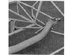
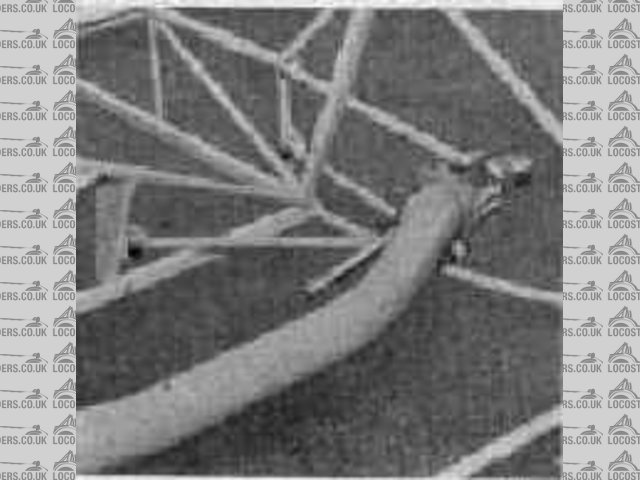
Chapman tried that as well it took a bit of finding
Rear de Dion suspension fitted on some Lotus Elevens
source http://lotuseleven.org/motor_racing_march_1956.htm
[Edited on 12/3/06 by britishtrident]
[Edited on 12/3/06 by britishtrident]
Rescued attachment MotorRacing3.JPG
|
|
|
DIY Si
|
| posted on 12/3/06 at 05:26 PM |
|
|
I know these things were back in the day an all, but damn that looks just a tiny bit flimsy!
|
|
|
MikeRJ
|
| posted on 13/3/06 at 07:06 PM |
|
|
Hmm, I didn't think too hard about it, but clearly the pivots of the A frame should be running at 90 degrees to the long axis of the car to
avoid any lateral movement of the axle in bump. That might make locating the the inner bracket problematic as it would have to be somewhere on the
transmission tunnel level with the standard outer bracket. Certainly an interesting variation on the standard Panhard/Watts linkage though.
|
|
|