Colnago_Man
|
| posted on 27/11/06 at 10:23 PM |

|
|
Wishbone Advice please.
Hello,
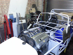
I have recentely acquired a rolling chassis .
How ever there are a few area on the car that concern me. So I would like a few opinions please, firstly (I'll post the others on new thread over
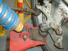
the coming days...) is the wishbone mounting of the lower ball joint, as the attached pic show the joint plate has four hole but only two are fixed to
the wishbone. Is this okay? It appears the whole weight of the front of the car is held on a couple of bolts of no more than 8mm in diameter...
Also could someone confirm the uprights are Cortina/Mk 2 Escort and take the M16 calipers?
Many Thanks.
PS Yes I know the shocks are Zeemerides, more to come about them I'am sure.
[Edited on 15/1/07 by Colnago_Man]
Rescued attachment wishbones.jpg
|
|
|
|
|
scutter
|
| posted on 27/11/06 at 10:36 PM |
|
|
Oh yes that should really have some bolts in it, 12mm 10.9 strength rings a bell and the uprights are Cortina items and will take M16 calipers.
P.s. Welcome to the madhouse. Dan.
[Edited on 27/11/06 by scutter]
The less I worked, the more i liked it.
|
|
|
RichardK
|
| posted on 27/11/06 at 10:36 PM |
|
|
That wouldn't bother me as I am using Maxi ones and they only have 2 anyway, can't you bang on a couple of nuts and bolts if it's
the aesthetics that concerns you.
P.S Welcome to the madhouse.
Rich
Gallery updated 11/01/2011

|
|
|
Colnago_Man
|
| posted on 27/11/06 at 10:52 PM |
|
|
Thanks for the welcomes guys.
Not worried about the look of the thing, more about the fact they we're designed to have 4 bolts rather than 2. So maybe I will try and add a
couple more bolts for piece of mind.
|
|
|
Volvorsport
|
| posted on 27/11/06 at 11:02 PM |
|
|
lets hope those zimmerframe dampers stay in one piece even before you drive it .
www.dbsmotorsport.co.uk
getting dirty under a bus
|
|
|
jambojeef
|
| posted on 27/11/06 at 11:03 PM |
|
|
Blimey!
2 x M12 10.9 bolts in addition to those other 2 bolts is giving a theoretically huge margin of safety which is ultimately irrelevant anyway when you
consider the cars supension mountings holisitcally.
The 2 M8 bolts at the base of the balljoint are effectively what those of us using Maxi bottom balljoints have and if you check the UTS for this
section it should be within acceptable limits depending on your car of course.
The only problem I can see is that owing to that weld bead under the balljoitn plate it appears as though the balljoint plate isnt sitting flat on the
wishbone. I guess this could lead to stressing the bolts in odd ways or increasing the loading - either way I would do something to get it to lay flat
|
|
|
scutter
|
| posted on 27/11/06 at 11:10 PM |
|
|
Didn't mean to scare monger, the 10.9 are what can withthe Cortina balljoints, so guess thats for the weight of a Cortina.
Anyway better safe than sorry.
ATB Dan.
The less I worked, the more i liked it.
|
|
|
locostv8
|
| posted on 28/11/06 at 08:15 AM |
|
|
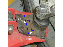
For my own peace of mind I would probably drill 1 additional hole thru both the balljoint and A arm between the two existing bolts then trim the plate
to look like it came that way. This would help if the car ever had to be inspected. It may be that the nut has been loosened and the shank of the
tierod end loosened but if not I would be more concerned with the lack of any thread sticking thru the nut.
http://wrangler.rutgers.edu/gallery2/v/7slotgrille/hssss/
|
|
|
Syd Bridge
|
| posted on 28/11/06 at 09:26 AM |
|
|
Reengineer the wishbone end and put the balljoint UNDER the plate. The bolts just stiop[ it falling out then.
|
|
|
Colnago_Man
|
| posted on 28/11/06 at 10:10 AM |
|
|
locostv8, I like your idea, I will trim the plate back and add an extra central bolt.
The welded seem will make it difficult to utilise the 'spare' holes.
Are there other wishbone designs out there that utilise the four bolts from the cortina ball joint?
Your right about the tie rod end, I think the nut just needs tightening up. When the car arrived every single nut on the car was finger tight only...
|
|
|
02GF74
|
| posted on 28/11/06 at 10:33 AM |
|
|
oooh deja vu time for me .....
there is lack of thread showing on the locknuts but this is ok if as you say the nuts have not been done up.
Also the track rod end and track rod - there looks to be an awful lot of thread visible meaning there is not a lot in the track rod end itself -
hopefully the tracking has not be set, if it has, you will be looking at extensions and shortening the track rods.
|
|
|
Colnago_Man
|
| posted on 28/11/06 at 12:20 PM |
|
|
Bugger...I had a nasty feeling this was going to be the case.
The wheels are near enough in track at the moment.
The racking I believe is Escort and the chassis is book width 42"?, so reading other threads on here I guess they will need extending.
Is it a case of removing some inches of the end of the rack then fitting a female/male sleeve to gain the extra width?
|
|
|
NS Dev
|
| posted on 28/11/06 at 12:37 PM |
|
|
book chassis plus escort rack should be fine, no extensions needed
Retro RWD is the way forward...........automotive fabrication, car restoration, sheetmetal work, engine conversion
retro car restoration and tuning
|
|
|
JB
|
| posted on 28/11/06 at 04:49 PM |
|
|
Ball Joint Position
As Syd says put the balljoint under the wishbone.
I would not run with the ball joint on top with 4 bolts let alone only 2 x M8`s, but I worry a lot!
John
|
|
|
t.j.
|
| posted on 28/11/06 at 07:23 PM |
|
|
Don't worry be happy ! 
My front axle of my motorcylce is only held by to m8x1.0 original!! And i'm driven it up to 170 km/h......
But i didn't say that there was a big axle from left to the right which gets the load.
So... How will this ball-joint will be stressed. As far i can tell are:
- the two bolts not placed in the centre.= stress.
- the ball-joint is not flat mounted= stress.
So get it right. BTW the ball-joint is at the cortina also on top mounted, so that don''t scare me off.
Maybe a maxi-balljoint fits in??
[Edited on 28/11/06 by t.j.]
|
|
|
scotmac
|
| posted on 29/11/06 at 02:09 AM |
|
|
Actually, Syd is correct. The plate should be *below* the bone, thus offloading the majority of the stress from the bolts themselves to more of the
entire bone plate. To make the conversion, do you need to do much more than just cutting a whole in the bone plate for the bj to go thru?
|
|
|
locostv8
|
| posted on 29/11/06 at 06:34 AM |
|
|
What Syd said is mostly correct but I doubt you would have to redesign the arm. Do the trimming and drill the third hole. Then, assuming that the
bottom of the plate is flat, as it seems, use a hole saw to cut a hole for the ball to stick thru (make it a tight fit) then bolt the balljoint up
from the bottom. It probably wouldn't be a bad idea to add a small gusset on both sides to help replace the strength taken away by the big hole
(most stock A arms have a lip around the end for reinforcement).
http://wrangler.rutgers.edu/gallery2/v/7slotgrille/hssss/
|
|
|
MikeRJ
|
| posted on 29/11/06 at 07:52 AM |
|
|
The balljoint is mounted on top of the wishbone in it's original application, and on top of the wishbone on the majority of book locosts, so I
don't think thats anything to worry about. Even the maxi balljoint is used in the same manner, i.e. only retained by bolts rather than being
mounted behind a plate of some kind.
It does seem strange that the mounting holes furthest away from the actual ball joint take larger size bolts, though perhaps these bolts also have
some other function?
|
|
|
Colnago_Man
|
| posted on 29/11/06 at 10:15 AM |
|
|
Very true Mike, does anyone have a Cortina manual that might show if the other two bolts are used for securing the plate or another function?
I also checkout of the TRE's last night, and you guys where right again, there was about 2 threads used on the track rod. So it does indeed look
like I'll need some extension.
Also tried to remove the TRE to check it out and the nut turns the complete bolt, and I guess ball. May need to cut it off.
Ho hum, and so it begins...
|
|
|
Peteff
|
| posted on 29/11/06 at 11:35 AM |
|
|
The 2 M8 bolts at the base of the balljoint are effectively what those of us using Maxi bottom balljoints have
My Maxi balljoints have two M10 bolts through 5mm plate. I can't see any advantage to having the joints under the plate in terms of stress on
the wishbone or joint. I did have one fail and it was the nut that holds the taper that stripped, probably due to my over enthusiasm with the ratchet.
If my MOT man saw the two holes without bolts he would have something to say so I would be tempted to cut the two off and make the plate triangular
with another bolthole as suggested earlier.
yours, Pete
I went into the RSPCA office the other day. It was so small you could hardly swing a cat in there.
|
|
|
MikeRJ
|
| posted on 29/11/06 at 12:21 PM |
|
|
quote:
Originally posted by Colnago_Man
Also tried to remove the TRE to check it out and the nut turns the complete bolt, and I guess ball. May need to cut it off.
Ho hum, and so it begins...
Stick a jack underneath the the TRE and push it up into the steering arm to lock the taper. Don't go mad, don't want to bend the steering
arm.
|
|
|
Colnago_Man
|
| posted on 1/12/06 at 05:04 PM |
|
|
Mike what a great idea, that worked a treat! Thanks.
The TRE's have seven threads holding them on. Is this enough?
When the TRE's come from underneath the upright this leaves the steering arms pointing down at almost 45 degrees. Can I taper the hole on the
top of the upright and put the TRE upside down so to speak?
I think that would help the steering arm geometry and give me another 4 threads on the arms as the rack to upright distance is shorter.
|
|
|
907
|
| posted on 1/12/06 at 07:16 PM |
|
|
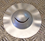
I cut my B/J's down and drilled two more holes, then mounted underneath.
Paul G
Rescued attachment cortina-b-j-s.jpg
|
|
|
MikeRJ
|
| posted on 1/12/06 at 10:06 PM |
|
|
quote:
Originally posted by Colnago_Man
The TRE's have seven threads holding them on. Is this enough?
The rule of thumb is to have 1.5 times the diameter of the thread engaged. The track rods have M14x2 threads so idealy you want about 21mm engaged.
7 turns x 2mm = 14mm thread engagement, not ideal. It would "probably" be ok, but of course this is a safety critical area, you absoutely
do not want the track rod end separating from the rack!
quote:
When the TRE's come from underneath the upright this leaves the steering arms pointing down at almost 45 degrees. Can I taper the hole on the
top of the upright and put the TRE upside down so to speak?
I think that would help the steering arm geometry and give me another 4 threads on the arms as the rack to upright distance is shorter.
This sounds a bit suspicious, the track rod isn't usualy at such an extreme angle in a book locost. Would it be possible to take a picture to
show us the location of the rack and angle of the track rod?
|
|
|
scotmac
|
| posted on 2/12/06 at 09:23 AM |
|
|
quote:
Originally posted by MikeRJ
quote:
When the TRE's come from underneath the upright this leaves the steering arms pointing down at almost 45 degrees. Can I taper the hole on the
top of the upright and put the TRE upside down so to speak?
I think that would help the steering arm geometry and give me another 4 threads on the arms as the rack to upright distance is shorter.
This sounds a bit suspicious, the track rod isn't usualy at such an extreme angle in a book locost. Would it be possible to take a picture to
show us the location of the rack and angle of the track rod?
Yes, in fact, with that big of an angle i would be worried about bump steer!!!
|
|
|