
Civic Based Midi
itsu-san - 8/4/10 at 05:35 AM
Hey Guys,
I've been lurking for the last month or so. I'm working through my design process and need some advice so i thought id post up my progress.
Basically my goal is max performance per dollar. Im a student so my budget is low. Im treating this as a learning exercise trying to do it cheap but
cleaver. I'm currently studying mechanical engineering at canterbury university, hence the solidworks and fea modeling.
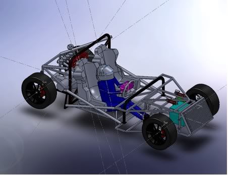
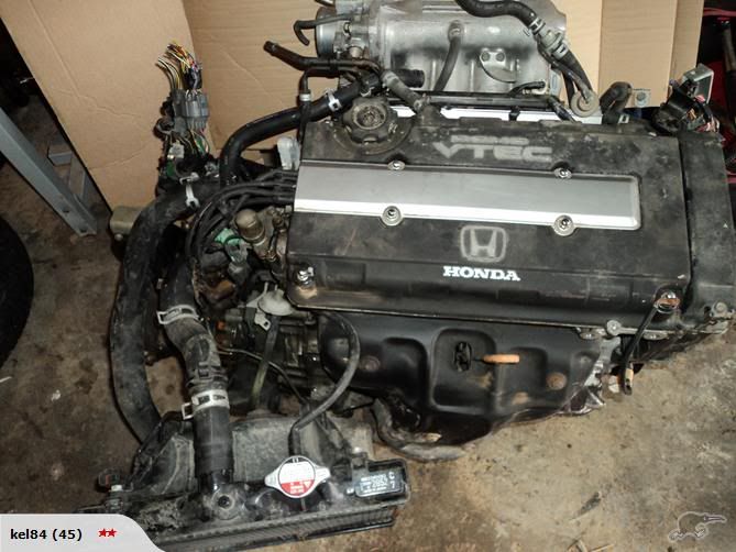
Bit about the car
honda d15b twin carb 105hp
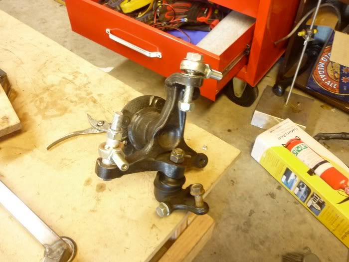
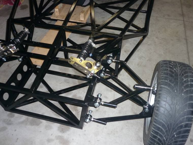
Mx5 front uprights
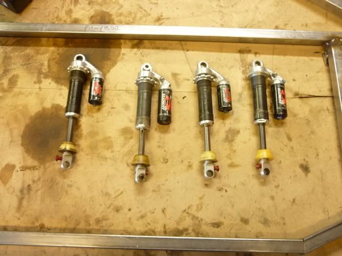
5th element mountain bike shocks actuated by push-rods
these allow a 1.33 motion ratio and full compression and rebound adjustments.
more to come
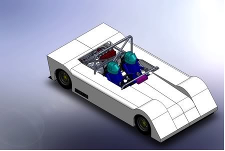
Spacial mock up
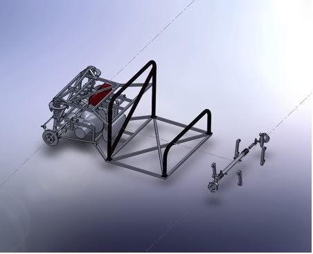
Rear suspension and wheelbase
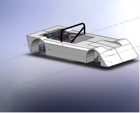
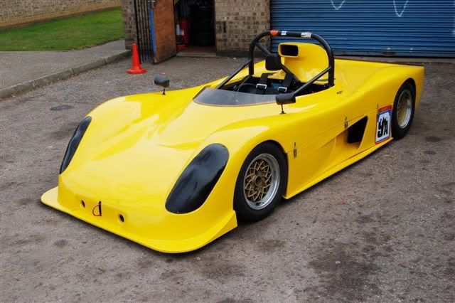
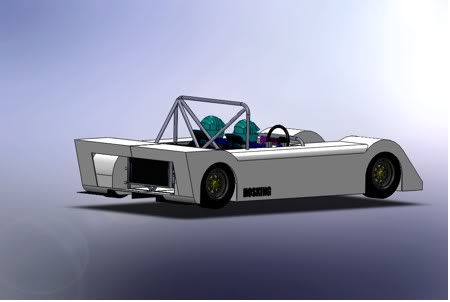
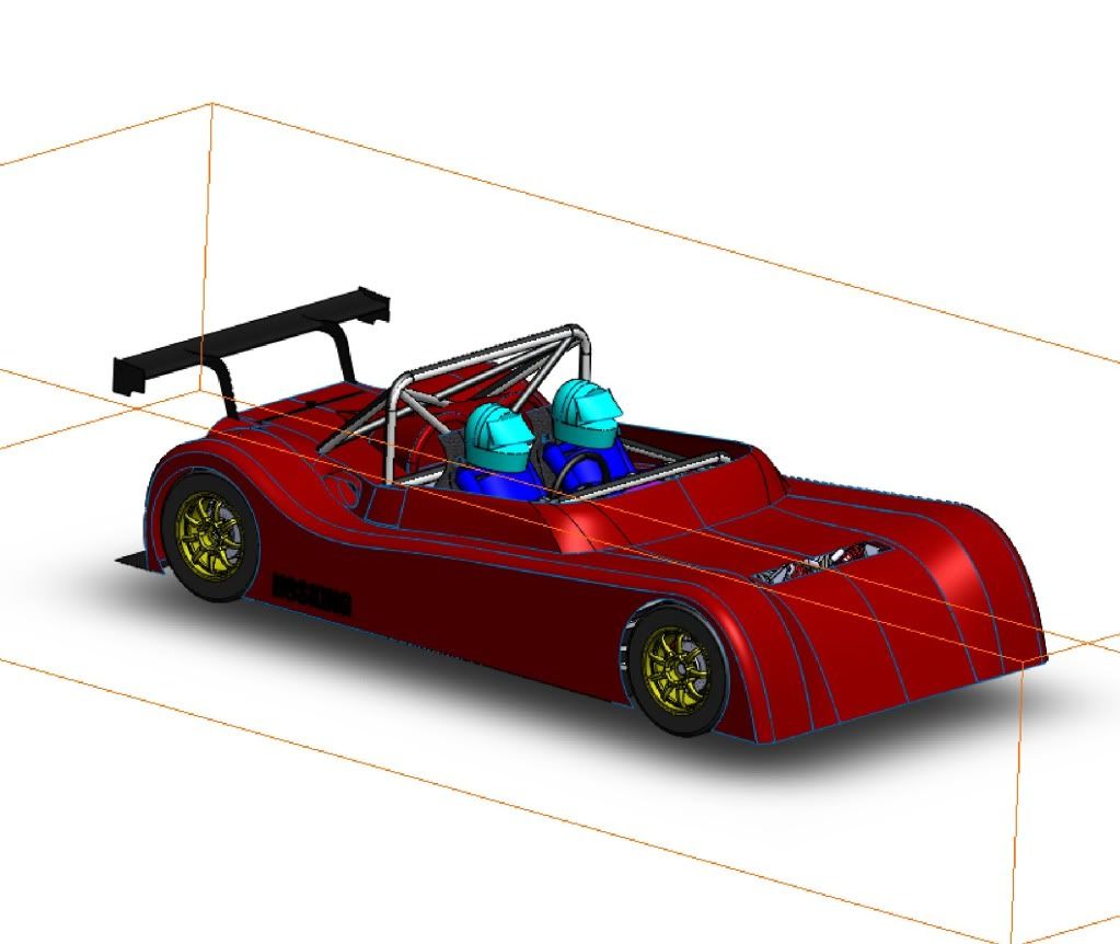
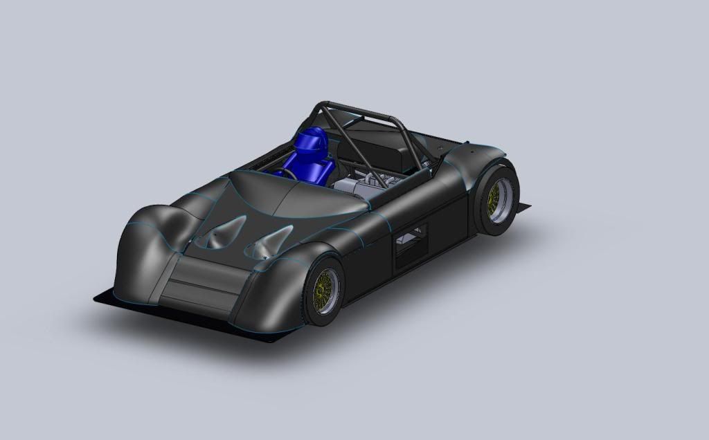
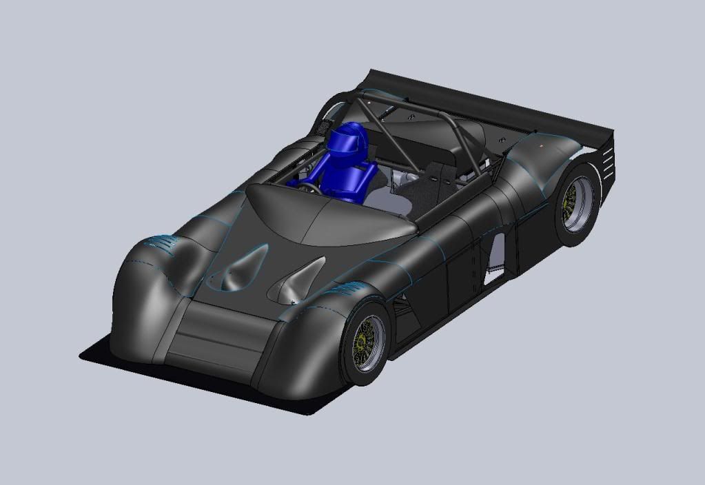
Fiberglass body
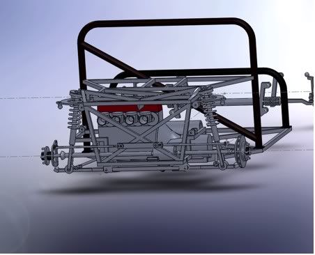
Rear suspension
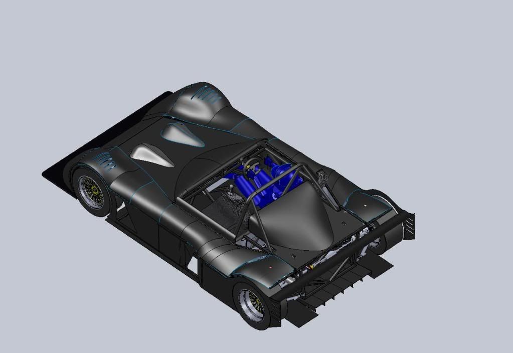
Style inspiration Radical
[Edited on 8/4/10 by itsu-san]
[Edited on 8/4/10 by itsu-san]
speedyxjs - 8/4/10 at 06:12 AM
Me likee that very much.
Oh and welcome to the madhouse 
Ivan - 8/4/10 at 06:45 AM
Love the body design - great for a one-off with no obvious compound curves yet still looks good.
Will watch this with interest.
MakeEverything - 8/4/10 at 07:48 AM
"posted on 8-4-10 at 05:35 "
You cant be a student........
Good luck with that. looks good, but why the smaller Civic engine when the Type R is so readily available?
cd.thomson - 8/4/10 at 08:17 AM
quote:
Originally posted by MakeEverything
"posted on 8-4-10 at 05:35 "
You cant be a student........
Good luck with that. looks good, but why the smaller Civic engine when the Type R is so readily available?
He's not been to sleep yet! Thats a sign on a true student 
Looks good. Running mountain bike shocks sounds a bit scary but what would I know 
gingerprince - 8/4/10 at 11:47 AM
quote:
Originally posted by MakeEverything
"posted on 8-4-10 at 05:35 "
You cant be a student........
My guess from his username (itsu-san) is that it's a Mr Itsu, from Japan, where the time is several hours ahead when Bargain Hunt has already
been on
MakeEverything - 8/4/10 at 11:50 AM
"I'm currently studying mechanical engineering at canterbury university"
My guess is you didnt read this bit!!
Richard Quinn - 8/4/10 at 12:03 PM
quote:
Originally posted by MakeEverything
"I'm currently studying mechanical engineering at canterbury university"
My guess is you didnt read this bit!!
Or...
University of Canterbury
www.uco.canterbury.ac.nz
20 Kirkwood Avenue
Ilam 8041, New Zealand
(03) 366 7001
gingerprince - 8/4/10 at 12:12 PM
quote:
Originally posted by MakeEverything
"I'm currently studying mechanical engineering at canterbury university"
My guess is you didnt read this bit!!
You'd probably guess right
eddie99 - 8/4/10 at 12:31 PM
Hahaha i love how off topic us locostbuilders manage to get!
EDIT: Love the car! look forward to hearing more about it!
[Edited on 8/4/10 by eddie99]
MakeEverything - 8/4/10 at 01:02 PM
quote:
Originally posted by Richard Quinn
quote:
Originally posted by MakeEverything
"I'm currently studying mechanical engineering at canterbury university"
My guess is you didnt read this bit!!
Or...
University of Canterbury
www.uco.canterbury.ac.nz
20 Kirkwood Avenue
Ilam 8041, New Zealand
(03) 366 7001
Fair point, but what was said was;
quote:
Originally posted by gingerprince
My guess from his username (itsu-san) is that it's a Mr Itsu, from Japan, where the time is several hours ahead when Bargain Hunt has already
been on
cheapracer - 8/4/10 at 03:27 PM
quote:
Originally posted by itsu-san
I'm currently studying mechanical engineering at canterbury university, hence the solidworks and fea modeling.
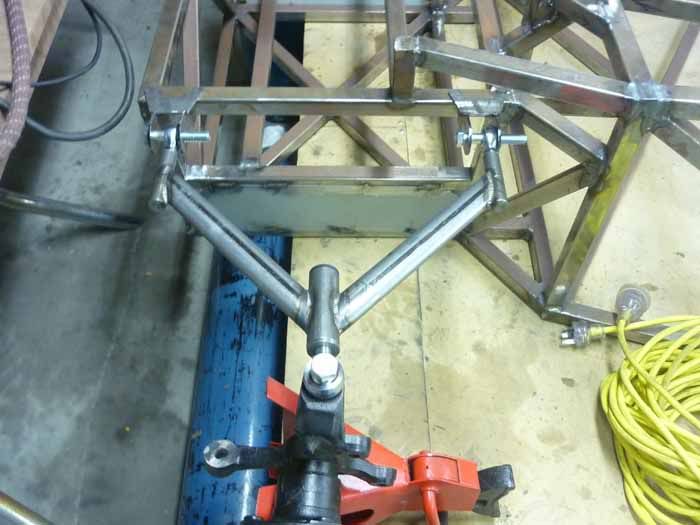
Rear suspension
[Edited on 8/4/10 by itsu-san]
Put your Mech Eng learnings aside for a moment and have a good look with your eyes at what the effects of the length of your toe links are going to
have on your uprights once in motion.
itsu-san - 8/4/10 at 10:17 PM
quote:
Originally posted by cheapracer
quote:
Originally posted by itsu-san
I'm currently studying mechanical engineering at canterbury university, hence the solidworks and fea modeling.
Rear suspension
[Edited on 8/4/10 by itsu-san]
Put your Mech Eng learnings aside for a moment and have a good look with your eyes at what the effects of the length of your toe links are going to
have on your uprights once in motion.
Mate those toe links are not dimensioned yet. But thanks, The reason i went with the smaller civic is i purchased the whole car running for $200nzd
compared with $3-4k that a type r would cost. Cheer to everyone for the comments. Im currently building my table so ill update soon
Ratman - 9/4/10 at 09:10 AM
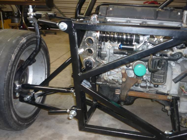
That's a good choice of componentry. Why not just use the Honda upright for the rear suspension. Looks a bit naf, but saves a lot of work and
$$.
Here's a link in NZ for MX5 parts: MX5 Mart: http://www.mx5mart.co.nz . Ross, who is near Hamilton.
Here's another handy contact http://www.constructorscarclub.org.nz
How do you plan to organize a handbrake? Good luck with the build.
[Edited on 9/4/10 by Ratman]
itsu-san - 10/4/10 at 07:38 AM
I am using the honda upright for the rear! Its just not fully modeled yet because of the irregular cast shape is a pain. Thanks for the links.
Im not sure about the handbrake, any idea on how its been done before? separate caliper for the handbrake would work but it's a pretty
inefficient solution.
Does anyone have pictures of h22 gearbox's cable actuated shifter?
Grant
Ratman - 11/4/10 at 07:28 AM
You can get certified for road use in some situations with a hydraulic handbrake. You could discuss this with whoever you plan to use for certifying.
Other idea is to use a rear caliper from some other bigger car (troll pic-a-part). A friend is using MR2 rear suspension to simplify this issue. Early
model Subaru had front wheel handbrake.. but non ventilated. You can probably use a non ventilated disc OK as your car will be very light. These are
much lighter unsprung weight. Cheers, Brian
itsu-san - 12/4/10 at 06:45 AM
Ah this isn't going to be road legal in the short term so ill go down that route if/when i want to road register it. Thanks
for the suggestions.
Thanks
Grant
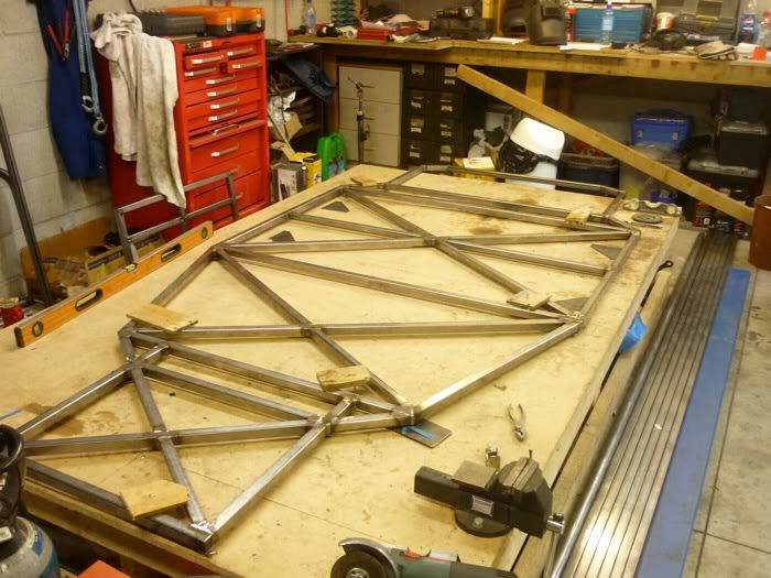
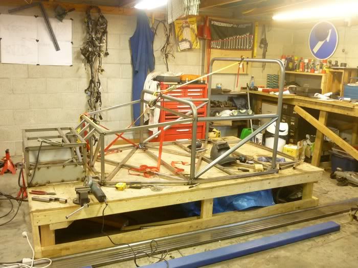
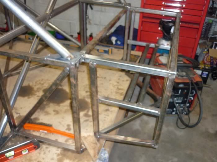
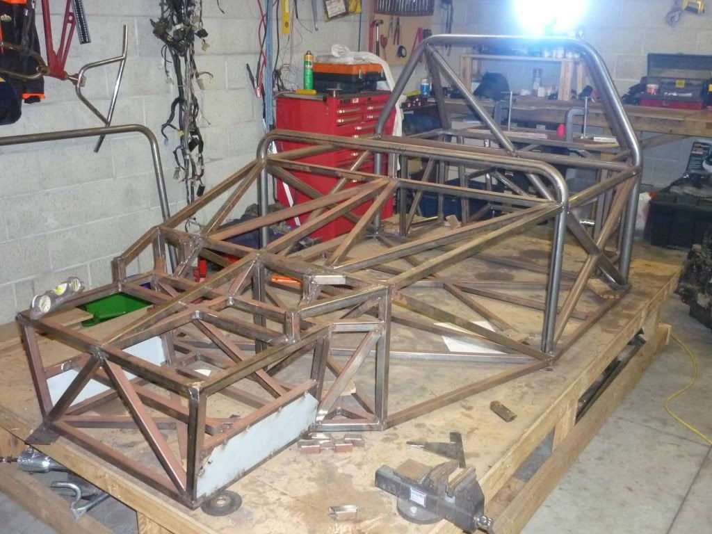
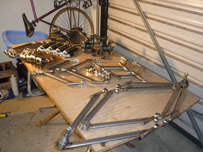
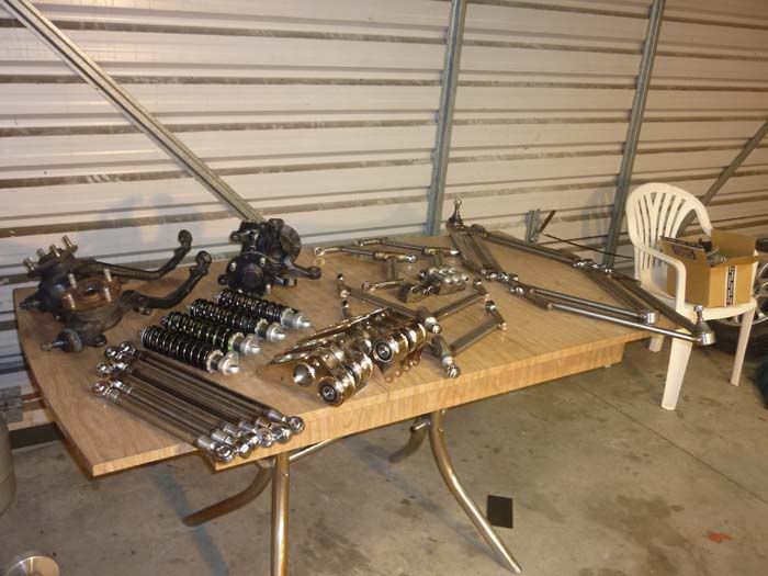
itsu-san - 16/4/10 at 05:00 AM
Finished build table. Geometric tolerance for the table is unacceptable for clamping the box section to it and welding on the table. So were going to
have to figure out the fabrication technique. Sat some junk on the table for fun.
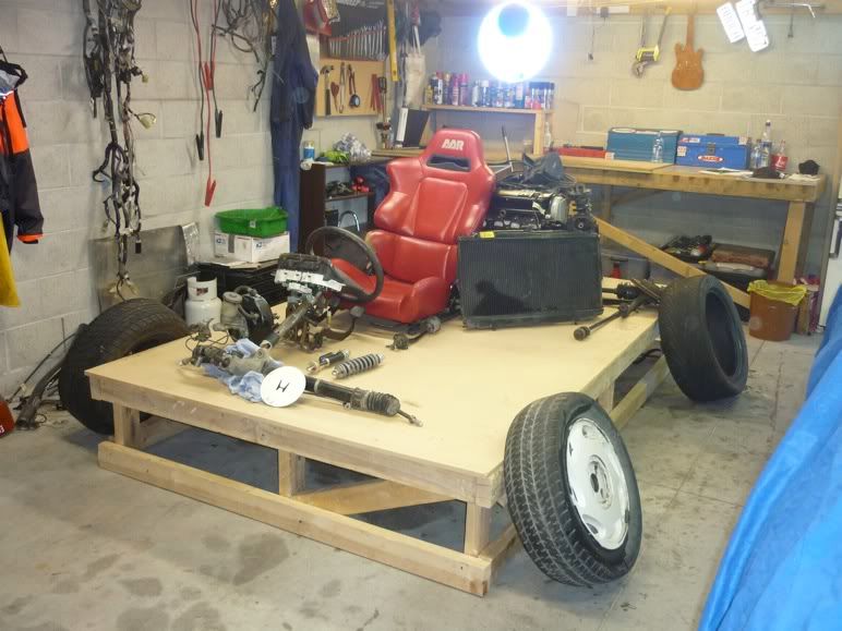
My mx5 parts should be here tonight so i can start a scale mock up and then continue with my cad model.
Thanks
G
Ivan - 16/4/10 at 05:58 AM
If you didn't sit in the seat, hold the steering wheel and go "Vroom Vroom" then you will never finish the project - so do it now 
Ps - build table looks very solid but a little low - would suggest a height of half way between your knee and hip.
Ratman - 16/4/10 at 08:29 AM
You'll be OK on that table. Make sure you put temporary triangulation members on to everything in EVERY direction as you go, and just tack the
joints until pretty much all the main tubes, engine mounts etc are in place. Don't let anything get off-square. Then take it off the table and
make a spit for it so you can hang it from the roof and spin it round for final welds. Then take the temporary triangulation members off.
If the table is a bit uneven, just shim it when you clamp (bolt or screw) the bottom rails down and get them true with a builder's level. Two or
three mm is good enough, just don't let the errors build up so you get more than this at the corners.
There's more than one way to skin a cat. But this procedure has served me well.
When you are working out your ride height, remember that the tyres squash down about 25mm at the bottom.
Fully locate all your pick-up points before you build the frame to them. Don't build a frame then fit pick-up points to it.
Check out the commonest racing rubber when deciding what overall tyre diameter you're designing for.
http://palmside.co.nz/tyres.asp?supplier=ALL&size=ALL&surface=ALL&type=ALL
I like these FTZ-RR tyres. And they're in your neighbourhood.
Cheers, Brian
[Edited on 16/4/10 by Ratman]
itsu-san - 16/4/10 at 09:16 AM
Thanks for your reply brian. Im thinking about using EX-NZV8
racing slicks, but those FTZ-RR's look nice! Once i get the front uprights ill model all the pick up points.
Cheers
G
itsu-san - 17/6/10 at 04:45 AM
almost finished exams. Much progress to come!
vtecmike - 13/7/10 at 06:58 PM
you should use the b16 lump!
itsu-san - 18/7/10 at 09:10 AM
[Edited on 18/7/10 by itsu-san]
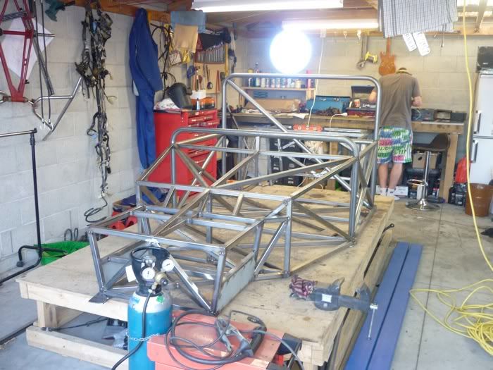
itsu-san - 15/9/10 at 10:10 AM
Hi all,
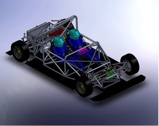
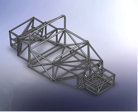
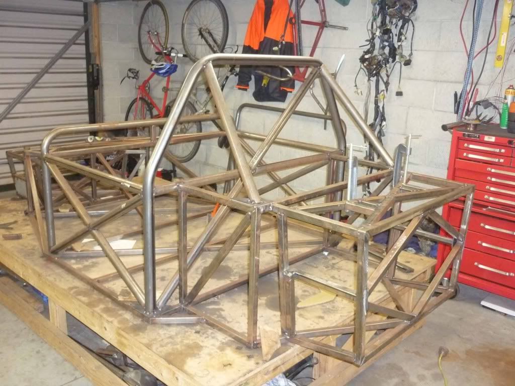
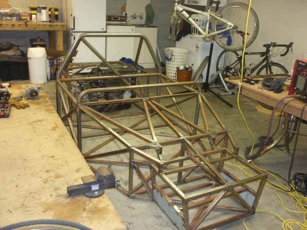
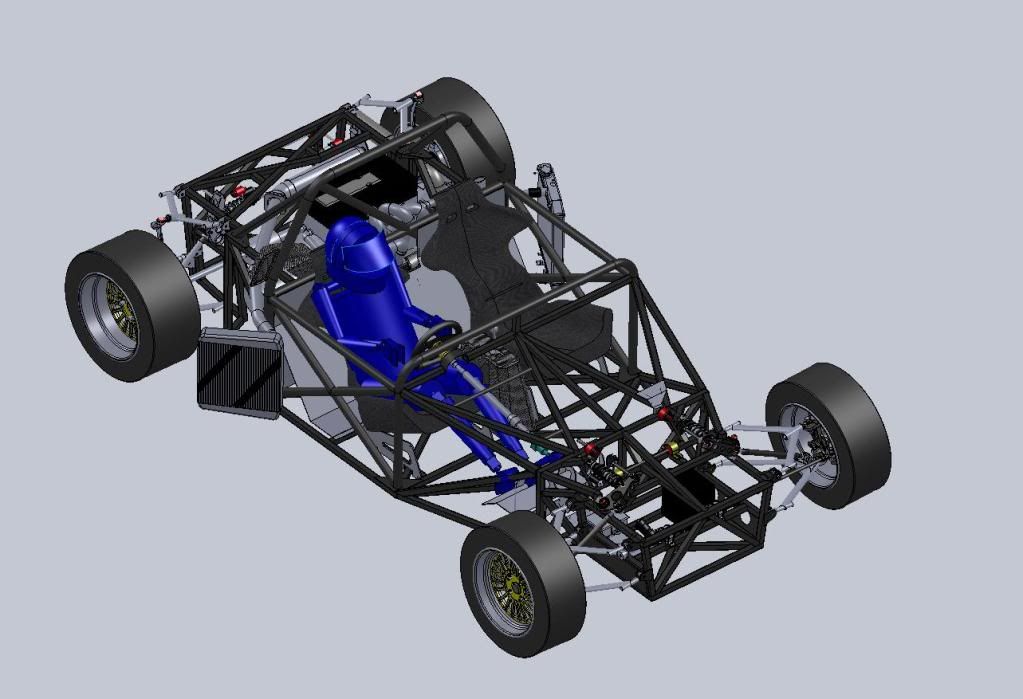
I've been working steady on this project and finally things are starting to take shape. Construction has started on the chassis and its going
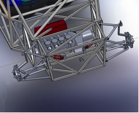
surprisingly well. Here's a rendering of the chassis and front suspension in their finial form. The rear sub frame and suspension still needs a
bit of work. Update tomorrow with pictures to prove this is actually getting built.
Thanks
Grant
Chassis
Front Suspension
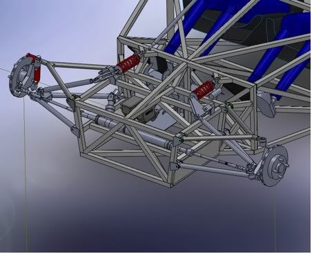
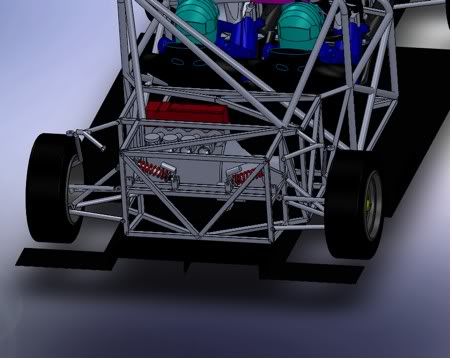
Rear Suspension
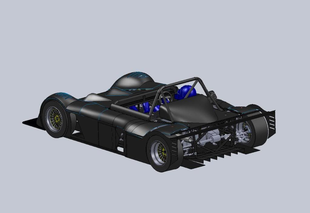
Mock up : Please don't judge me on the body model it was only a QUICK model for motivational purposes
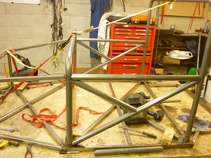
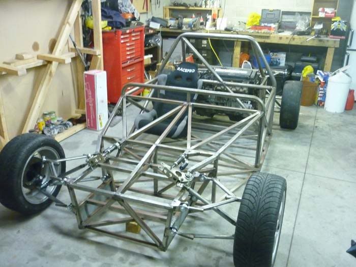
itsu-san - 16/9/10 at 07:37 AM
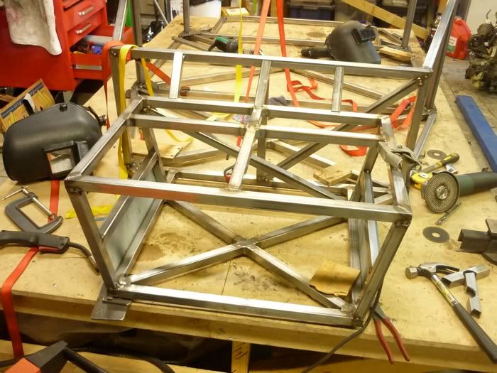
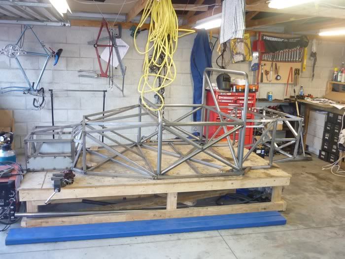
Hi guys heres the evidence that this thing is actually getting built.
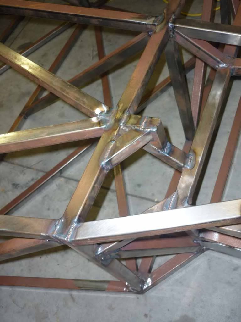
Chassis base welded and clamped to the build table. Square and level to within cuoee
Flat
Coming together
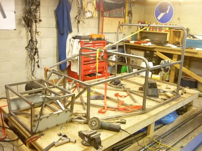
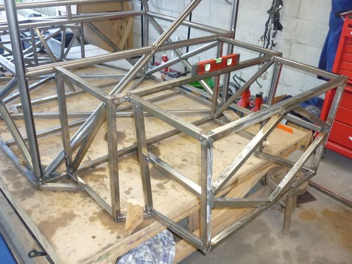
Front Subframe
3d
Shocks
Front Upright
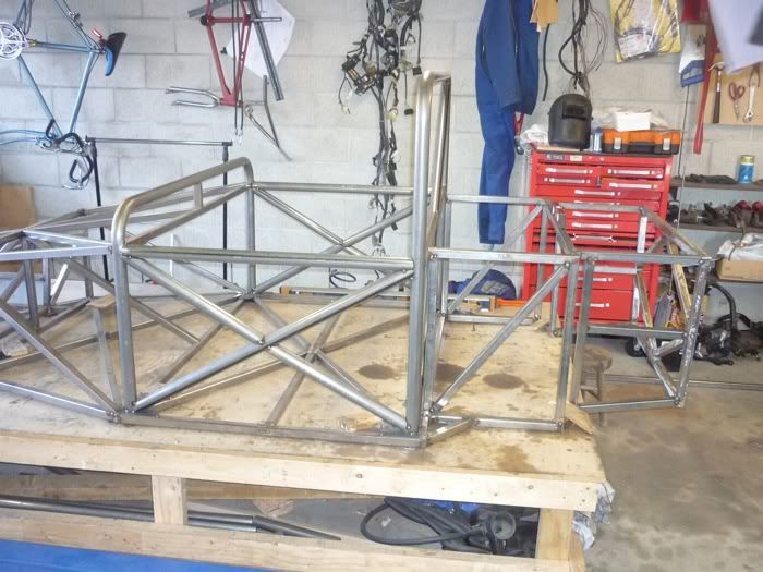
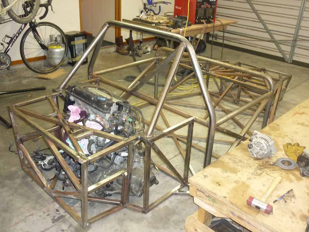
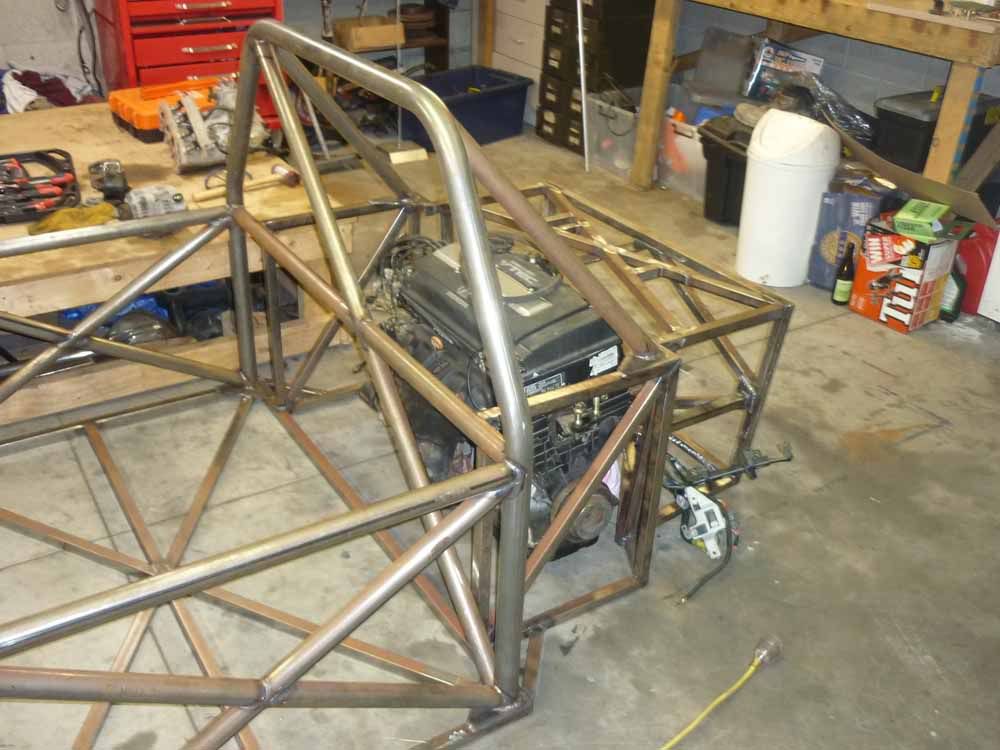
Roll cage
Rollcage side bars
Ivan - 16/9/10 at 02:33 PM
Will watch the build with interest.
MakeEverything - 19/9/10 at 05:26 PM
Looks fantastic.
Should the side cross members go all the way through? Frontal impact might see the car fold in half otherwise?
MakeEverything - 19/9/10 at 05:27 PM
D'oh, just seen the other bits lying on the table! Sorted.
itsu-san - 20/9/10 at 11:11 AM
Thanks! All the side bars are in now ill put pics up soon.
One of the opportunities you just can't pass up. 160hp Engine and gear box + drive shafts + etc for $350
What ya gunna do? 8-)
[Edited on 20/9/10 by itsu-san]
MakeEverything - 20/9/10 at 03:01 PM
quote:
Originally posted by itsu-san
What ya gunna do? 8-)
[Edited on 20/9/10 by itsu-san]
....Turbo it!!
itsu-san - 30/10/10 at 05:39 AM
Hi All,
The chassis is just about ready for final welding. A handful of tubes to go in the rear sub-frame and its done.
Exams are over on the 11th so expect to see a lot more progress in the near future
Cheers
Grant
[Edited on 30/10/10 by itsu-san]
MakeEverything - 30/10/10 at 11:27 AM
Looks awesome, well done.
Cant wait to see it on wheels.
Gakes - 2/11/10 at 09:19 AM
looking good dude. looking forward to the updates
renrut - 11/11/10 at 01:37 PM
Think you might have missed a trick with designing the rear suspension.
I've done a similar build with a small fiat. I copied the front suspension pick up points from the front chassis and used them as the basis for
building the rear. I even used a steering rack for the rear toe and kept the track width the same. Only thing that was a pain was making some adaptors
up to mount some handbrake'd calipers on the front hub carriers but thats 2 laser cut plates compared to a lot of possible suspension woes.
Looks good, I'm immensely jealous of the working space!
kb58 - 12/11/10 at 02:45 AM
quote:
Originally posted by renrut
Think you might have missed a trick with designing the rear suspension.
I've done a similar build with a small fiat. I copied the front suspension pick up points from the front chassis and used them as the basis for
building the rear. I even used a steering rack for the rear toe and kept the track width the same...
Assuming that the same uprights are used at all four corners, it means the front and rear RC is in the same place, unless the suspension arms
werevery carefully designed to somehow put both front and rear RCS where they're wanted.
itsu-san - 17/11/10 at 07:10 AM
Ratman - 12/2/11 at 04:27 AM
Looking very good Itsu. One thing to bear in mind is that the triangulation makes for a stiff chassis, but you only get the full benefit of it if the
suspension attachment points (including bell cranks and shock mounts) are at the triangulation nodes. But this is generally rather hard to get
perfect and some compromise generally results. I'm guessing that the rear-most box on your chassis is there to take the rear suspension. So, is
it possible to make the corners of the box, the same points as the inboard ends of the A arms? Or would the chassis members then interfere with
internal organs? These aren't questions.. I'm just wondering aloud. How's progress been over the summer?
itsu-san - 13/2/11 at 09:33 AM
Hi Ratman,
I have been working 6 days a week all summer, inspite of this there has been lots of progress although mostly in theoretical understanding and design
work. Tumbling further down the rabbit hole so to speak.
The front suspension is almost ready for fabrication. Just awaiting final design of inboard mounts and then they will be laser cut.
Part of the reason for the slow physical progress has been due to time spent writing our own program to model the suspension geometry.
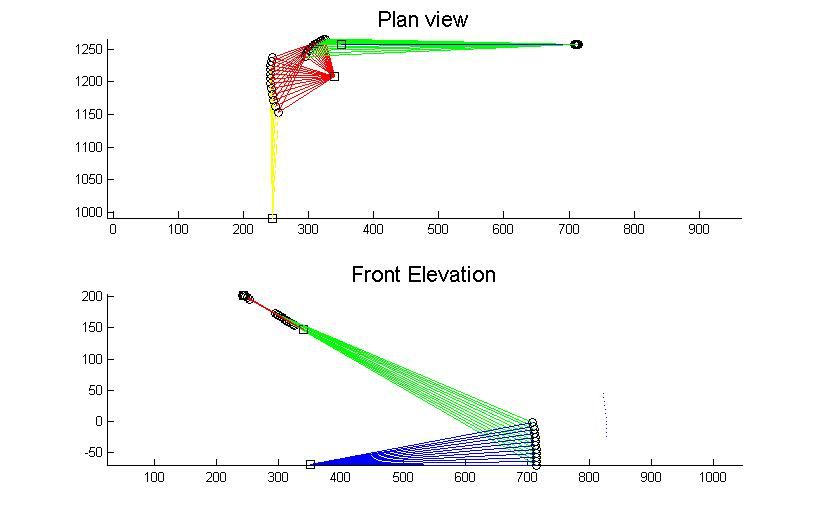
Rear suspension
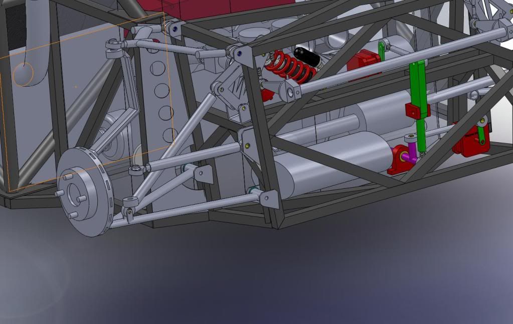
Still work to do here.
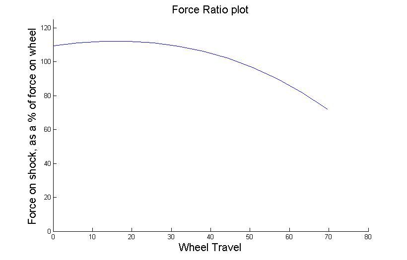
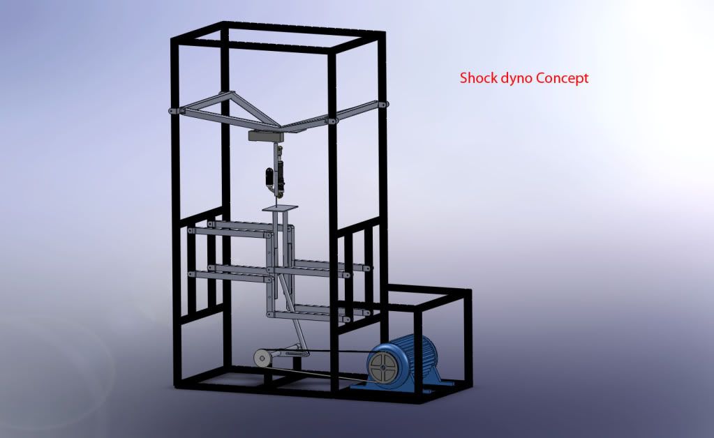
Building a shock dyno too
Thanks for the interest!
G
[Edited on 13/2/11 by itsu-san]
Ratman - 25/2/11 at 09:49 PM
I hope you (and your project) are OK after the Earthquake. I have in my mind your garage full of liquification silt and everything in the workshop
strewn across the floor. Tell us it isn't so.
http://www.youtube.com/results?uploaded=w&search_query=christchurch+earthquake+footage&search_type=videos&suggested_categories=25&page
=2
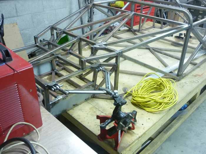
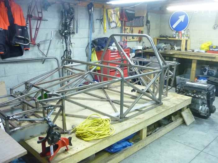
itsu-san - 27/4/11 at 10:53 AM
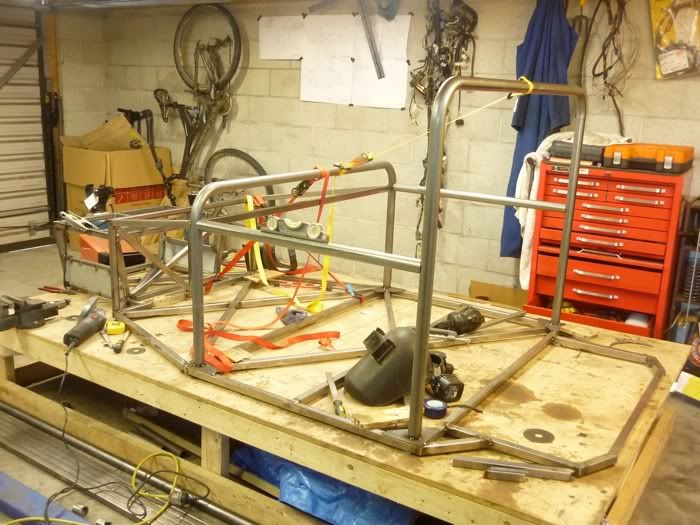
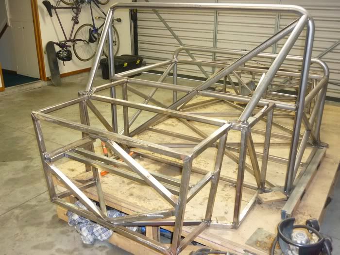
It's been awhile since the last update but im really happy with how the project is going. The suspension has been modelled, analysed, optimised
and designed in details down to the last nut and bolt! I decided to cut out the old 38mm OD roll bar and get a new roll bar bent up in 44mm OD. It
brings the car in line with the new NZ motorsport regulations and i think the new design looks a bit better aswell. Managed to get it in there without
disturbing the frame too much. Chassis has now got all the major tube members tack welded in place and is ready to be fully welded. I've got
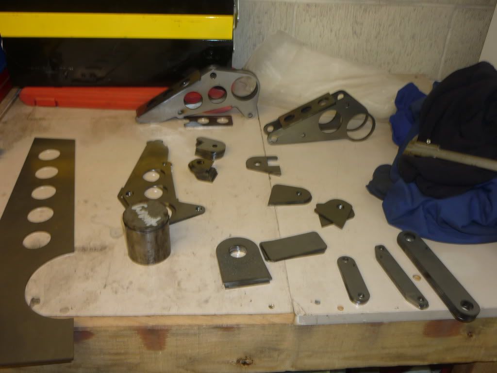
about 70 parts getting laser cut at autobend in the next week or so which will take the project a massive step foreward when they arrive. I've
been on the lathe for the last two days turning up spacers for the rod ends and various bit and pieces to help jig up the suspension plates onto the
chassis.
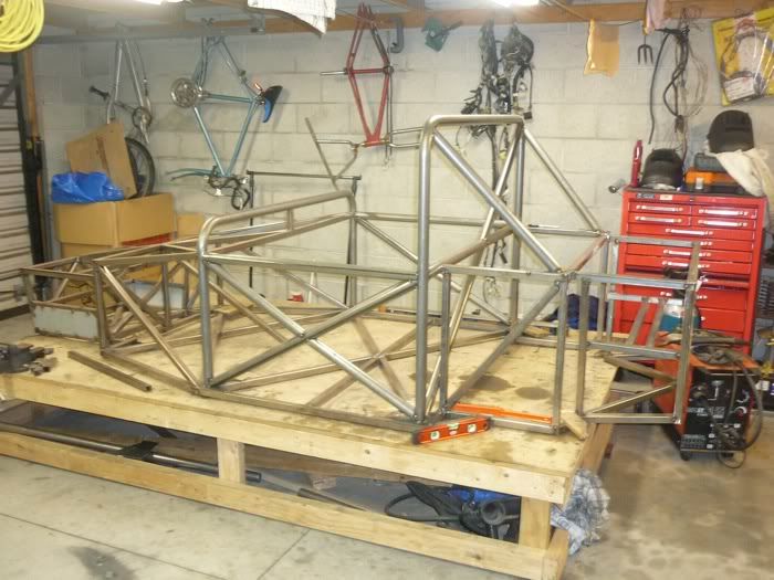
Front of the chassis
Rear of the chassis
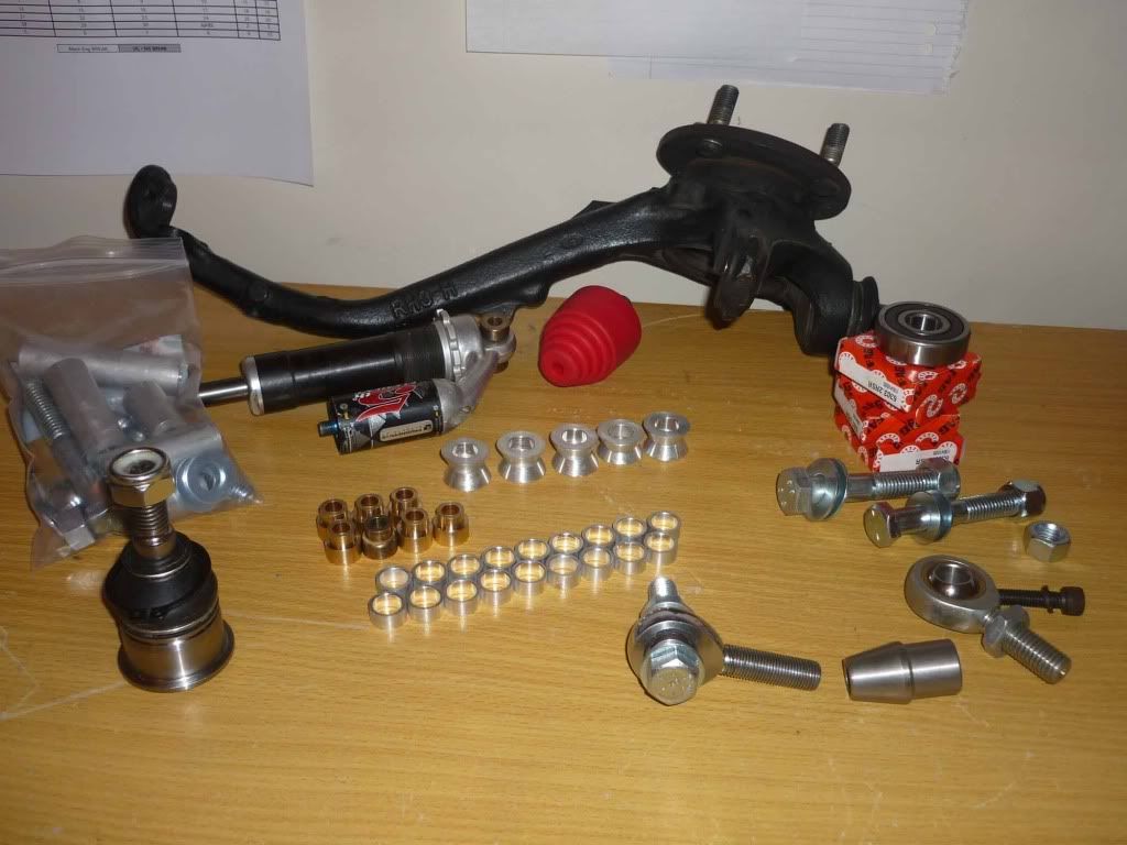
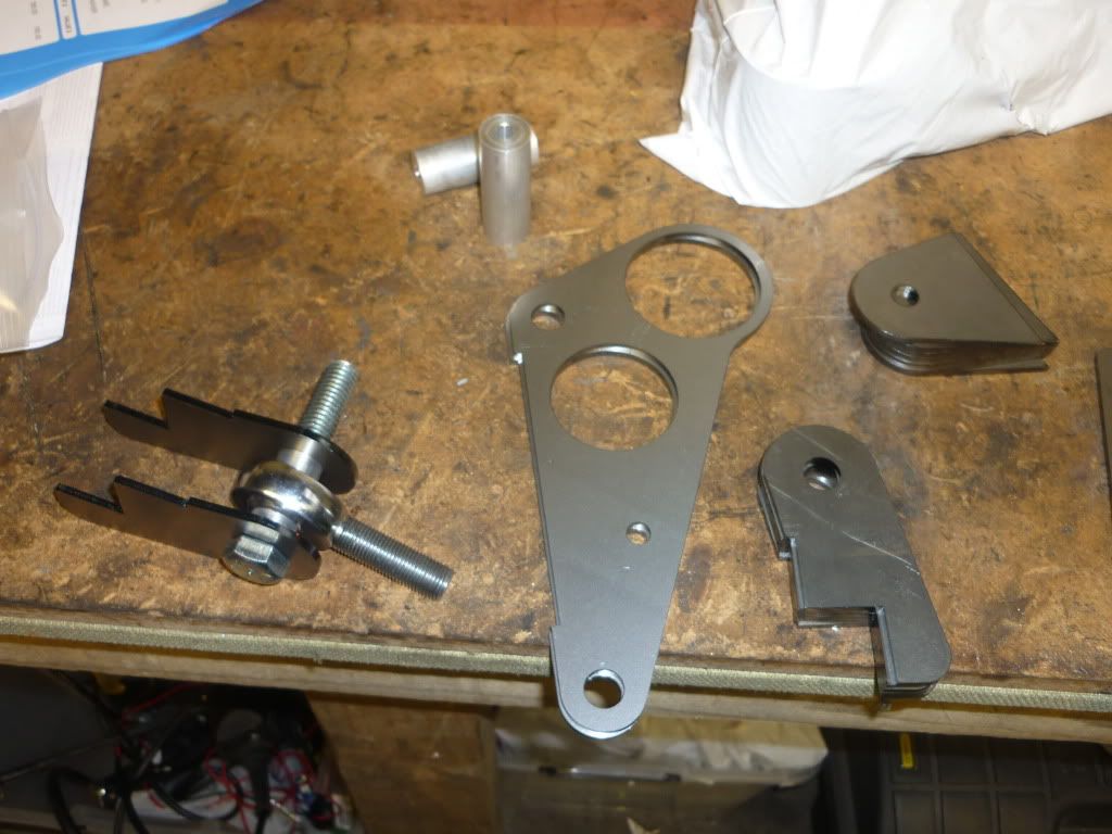
starting to aquire a few of the suspension parts
Cheers
Grant
Miks15 - 27/4/11 at 11:58 AM
Its looking good, completly missed this thread first time around but glad i spotted it now.
itsu-san - 28/4/11 at 04:24 AM
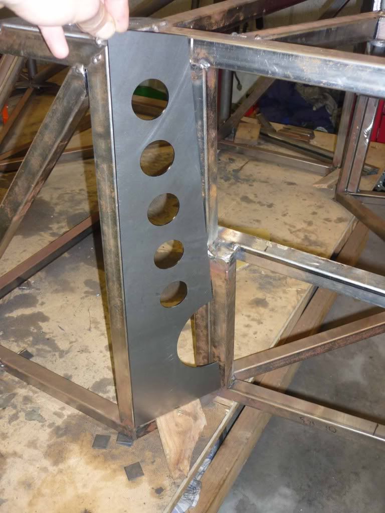
First laser cut parts arrived today the rear chassis plate! Fits nicely!
HowardB - 28/4/11 at 06:48 AM
looks great, I am really impressed....
keep up the pictures,.....
Livio - 1/5/11 at 02:25 PM
Those red boxes at the rear of the car are actators for the gear linkage?
Do you have any specific information about them? How are you going to control them?
How strong and robust are they?
v8kid - 1/5/11 at 02:56 PM
And why are they mounted remotely?
Doug68 - 2/5/11 at 10:31 AM
Hi Istu san,
Check out this blog post it might give you an idea for a simpler gear shifting mechanism.
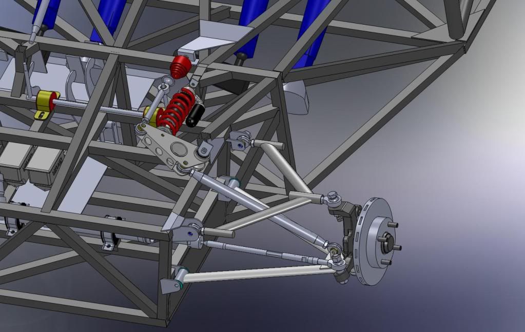
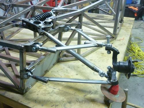
I realize it may well be a CAD work in progress, but the brackets on the wishbones that the push rods attach to, look to weedy to me. Also the top
rear A looks like it might run out of motion on the bearing before bottoming out. Beware of that sort of thing as if it happens the results could be
catastrophic. If its close you my find yourself running out of camber adjustment.
This top outer bearing doesn't need to be a threaded unit as the two inners should give you the adjustment you need if you can change to a press
in type and cant the end fixture to be square at 1/2 travel that might be a better solution.
Keep up the good work!
Edit:
looking at the pictures it struck me the tube for the chassis is bright.
Seeing as NZ doesn't make any steel tube, that means its imported, so do you know what it is and where its from?
I'm afraid it might be Australian as the bright tube from Australia is generally GR250, used for furniture as its nice and easy to bend and not
what I'd use for a chassis.
The blue painted material is what's normally in Locost construction in Aus as its GR350 (and printed on the side of tube as such).
Hope I've not just ruined you day. 
[Edited on 2/5/11 by Doug68]
[Edited on 2/5/11 by Doug68]
[Edited on 2/5/11 by Doug68]
britishtrident - 2/5/11 at 11:05 AM
Sweet --- "looks right is right".
In the words of Wayne and Garth "We are not worthy ! "
itsu-san - 3/5/11 at 03:27 AM

itsu-san - 3/5/11 at 03:39 AM
Hi Doug,
I really appreciate you taking the time to eye over my design. You are correct old cad model! Both the rod end motion range and push rod mount have
been changed. Ill post latest design when i get home.
Ive changed the adjustment set up for the A-arm so that camber can be adjusted without having to remove the arm, ill post a pic of this too.
The steel for the chassis is 25.4x25.4x16 As1163 - C350/450 ie 350 mpa yield same as what you're using.
Cheers
Grant
itsu-san - 22/5/11 at 10:59 AM
ENGINE IN DAY!
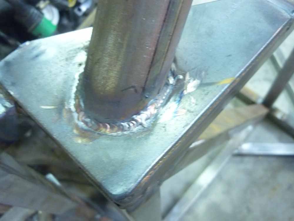
All the tig welding done by a mate. He's super talented with that torch! Slight problem with the engine fitment but other wise stoaked to bits!
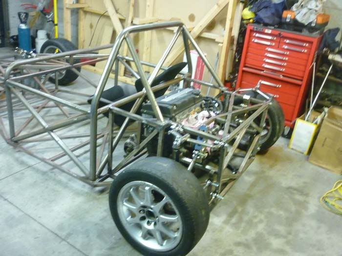
itsu-san - 7/6/11 at 01:21 AM
Quick update,
There's been alot of progress lately. The engine has been in the fame and the engine mount have been fabricated and painted. The engine sits in
the frame really nice.

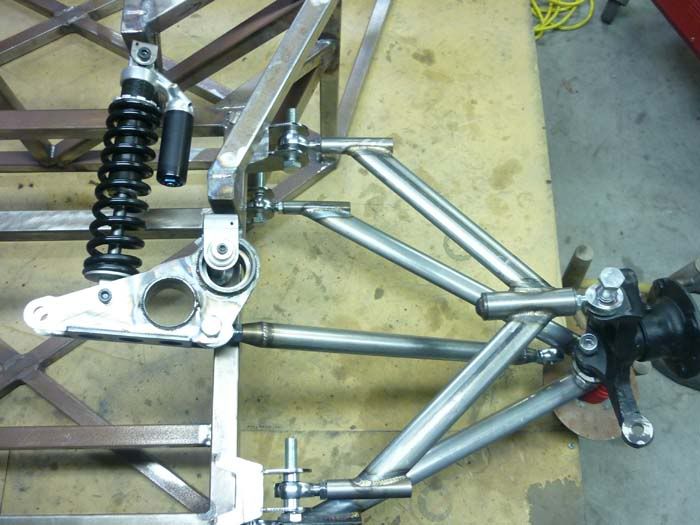
Started the wishbones.
Thanks
Grant
itsu-san - 4/7/11 at 01:02 PM
Hope to be rolling in 7 days!
ceebmoj - 4/7/11 at 03:27 PM
interesting update. What beings are you planning on using in the rockers?
coyoteboy - 5/7/11 at 12:37 AM
Rod ends in bending?
itsu-san - 5/7/11 at 07:40 AM
Thats all just sitting there at the moment. Waiting untill i get the rockers back from being coated to press in the bearings. The rod ends are not
loaded in bending. Thanks
coyoteboy - 5/7/11 at 10:20 PM
Looks to me like they are in any sort of braking or acceleration?
itsu-san - 6/7/11 at 08:04 AM
The very nature of a rod end means it can't react a bending load. I can see what you're saying though. The rod ends will be in shear but
thats fine. Thanks
v8kid - 6/7/11 at 09:01 AM
To be pedantic rod end shanks are in bending and will fail (eventually - if they are loaded enough) where the locknut mates with the wishbone.
Can be a bit more than pedantic in the case of high loads for example in the bottom outer bearing but I see you have that sorted. Aurora have an
excellent article on bending loads in rod end shanks including worked examples. Looking at the sizes used I'd be very surprised if it was a
problem though
Cheers!
coyoteboy - 6/7/11 at 09:25 AM
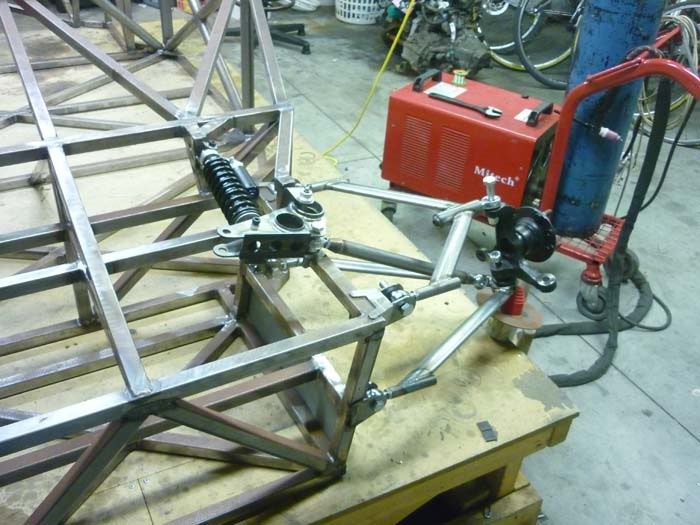
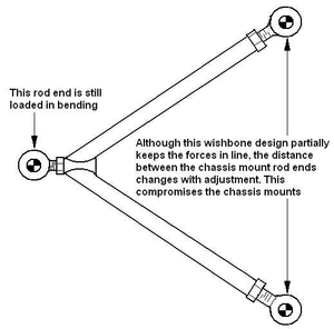
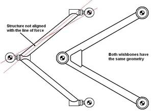
I think you're missing what I mean. In your upper A arm the two inner joints hold the arm rigid front to rear, the top rod end (when loaded by
braking torque) will be trying to move forward, resisted by the triangle. At which point your outer rod end is loaded in bending. Diagram time.

Your inner two are in shear primarily in he same situation (again, not ideal for a threaded part but possibly more acceptable), but there is a bending
component to that loading due to the misaligned load paths. I'll try to do a better diagram later.
Rod ends are designed to be loaded purely axially.
EDIT > I don't have to, an expert already did it for me:
http://www.formulastudent.de/academy/pats-corner/advice-details/article/pats-column-rod-ends-in-bending/
[Edited on 6/7/11 by coyoteboy]
itsu-san - 6/7/11 at 10:30 AM
Ah yep im following you now. Thanks for the diagrams. You are right the outer rod end will be in bending. I think it will be ok but ill do some worst
case calculations tomorrow and post them up. Sometimes you have to compromise pure loading for other important atributes such as easy camber
adjustment and more economical construction. I better be able to justify myself on this point!
HA thats an excellent article and one i wish i had read before spending two weeks building these arms! Not exactly helpful when the only advice is to
'Build some non adjustable arms"
[Edited on 6/7/11 by itsu-san]
coyoteboy - 6/7/11 at 11:08 AM
Oooh an I just threw together an FE example to show you the inners in bending too (forgive the rather crude box section steel lol):
Inners free to rotate but not translate, load applied at the outer rod end vertically:
http://www.dropbox.com/gallery/10257533/1/FEA?h=43392e
[Edited on 6/7/11 by coyoteboy]
v8kid - 6/7/11 at 11:47 AM
For those who prefer to use the old ways
BTW watch out it's big!!!


Cheers!
itsu-san - 6/7/11 at 11:53 AM
Hey thanks for that. FEA can be a good visualisation tool. Do you mind explaining you BC's and solver method? What was your load/magnification
factor? Cool seeing the compression buckling! Do you not think the inboard bending is in the arm rather than the rod end though? Have you seen any
top a-arm designs that utilizes pure tension and compression loading while still having independent camber adjustment?
Cheers
Grant
[Edited on 6/7/11 by itsu-san]
itsu-san - 6/7/11 at 12:06 PM
Thanks v8kid! Interesting article. I have some thinking to do.
kb58 - 6/7/11 at 01:31 PM
That's why it's so important to use check-nuts and that the seating surface is square to the shank. Tightened down, it moves the points of
highest stress away from the threads and onto the check-nut mating surface. And of course, also keeps the part from backing out!
[Edited on 7/6/11 by kb58]
coyoteboy - 6/7/11 at 01:32 PM
quote:
Originally posted by itsu-san
Hey thanks for that. FEA can be a good visualisation tool. Do you mind explaining you BC's and solver method? What was your load/magnification
factor? Cool seeing the compression buckling! Do you not think the inboard bending is in the arm rather than the rod end though? Have you seen any
top a-arm designs that utilizes pure tension and compression loading while still having independent camber adjustment?
Cheers
Grant
[Edited on 6/7/11 by itsu-san]
Ignore the values, they were only put in to help aid visualisation of the problem as you say, and show bending in the rod end shank holding sections.
It was done in Solidworks using the static solver (FFEPlus) It used an unrealistic 5000N force at the outboard end with the force in the forward
direction as if under hard braking (not following the arm deflection, though that may be more accurate thinking about it, but the difference is
minimal). The inner joints were allowed to rotate freely in horizontal plane but constrained in location. Another in there now with narrowings for the
shanks of the rods, just highlights the bending in those spots.
The main bending moment is carried by your welded joint and the arm outboard of it, but there is still a bending moment in the rod shaft/arm joint
location (though fairly small). I don't have time to go through a full model (if you have the dims I can do it in about 2 weeks time but
I've a few things on my plate at the mo)
I've not seen any adjustable arms using pure tension/compression no, but I've no been looking tbh, I just spotted yours and thought you
should be aware of the possible issue in case it causes a safety issue. Most of the time we use adjustments at the upright instead, or just re-make
the arms with new geometry. It'll probably be fine for testing as you've covered the main lower arm outer joint problem, but I'd not be
using it on the road, personally.
v8kid - 6/7/11 at 01:49 PM
quote:
Originally posted by kb58
That's why it's so important to use check-nuts and that the seating surface is square to the shank. Tightened down, it moves the points of
highest stress away from the threads and onto the check-nut mating surface. And of course, also keeps the part from backing out!
[Edited on 7/6/11 by kb58]
Interesting I never considered that. To maintain the stress distribution wouldn't the lock nut have to be tightened up to the UTS? If not as
deflection commences one side of the lock nut will loose contact with the shoulder on the wishbone I would think.
Tightening the lock nut up that tight would really worsen the bending stress though - possibly -I need to do a force diagram of it but can't be
bothered just now. I'll try googling it
Cheers!
PS I may be wrong here it depends on how the lock nut deforms it could be a bit of both scenarios leading to an overall gain - just as KB says. Phew -
it takes a while for my brain to get into gear but at least I can put it down to incipient alzheimer's at my age.
coyoteboy - 6/7/11 at 02:18 PM
Anim of the bending...
http://www.flickr.com/photos/bucklevision/5908375291/in/photostream
Regardless of check nuts, you still have the shank in bending (unless you're making no use of the check nut and have it right out at the bearing
end, minimising shank extension.
Doug68 - 6/7/11 at 11:59 PM
This is not that an uncommon thing to do, the picture below is from the RCR cars website and their vehicles
seem pretty well respected.

I think that the only answer is to know the specs on the parts involved and do the math to see if you're going to get anywhere near causing a
part failure.
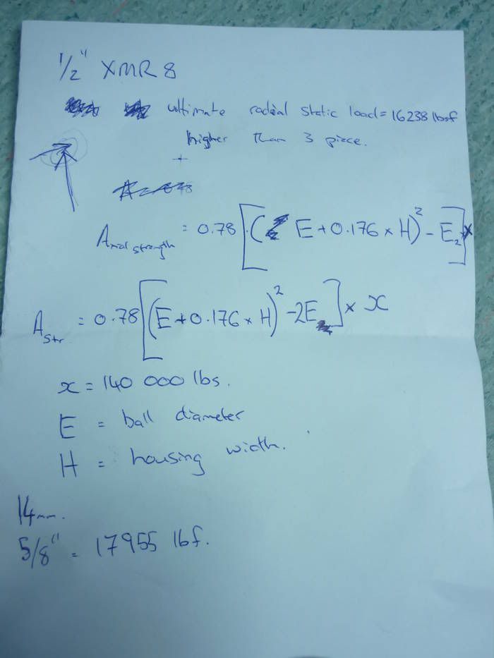
itsu-san - 7/7/11 at 04:57 AM
Interesting doug.
I managed to get some specifications for the rod ends today. The rod ends i have are for motorsport use and are of two piece design with a special
ball retantion chamfer which apparently makes them able to take a significant axial load! They are made from cro-moly and the shank strength is
similar to grade 8.8 bolts.
Just trying to find time to run the numbers now.
Got the rockers back from the platers and pressed the bearings in.
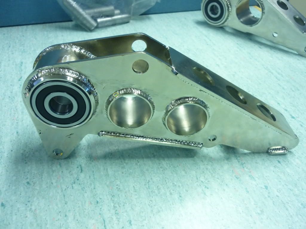
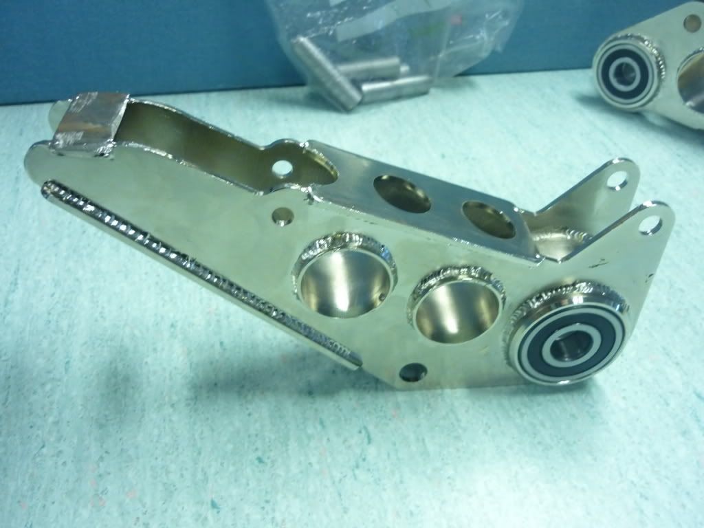
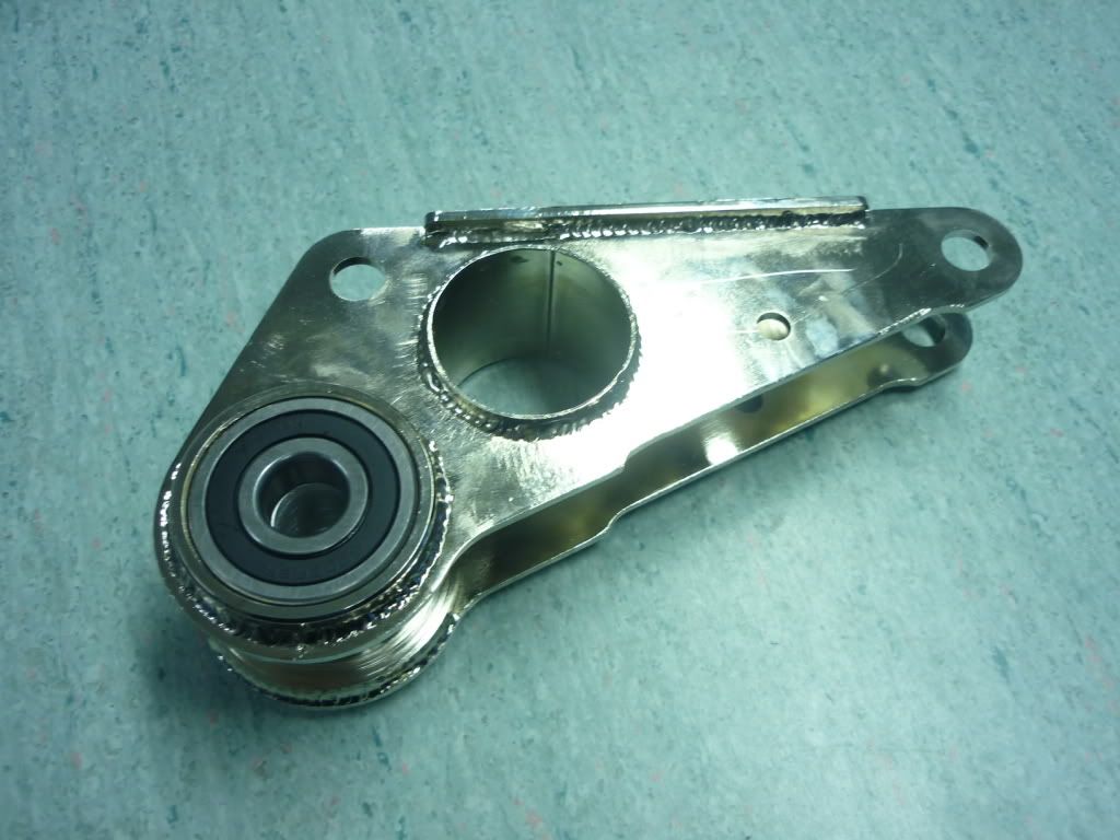
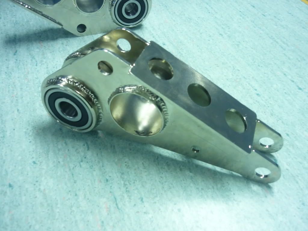
Thanks
G
[Edited on 7/7/11 by itsu-san]
[Edited on 7/7/11 by itsu-san]
[Edited on 7/7/11 by itsu-san]
coyoteboy - 7/7/11 at 01:42 PM
Doug - those bones are tiny, making the leverage a lot lower, but I still don't think it excuses it - it's poor (sorry!) design for the sake
of easy manufacture. It's the number one, first and primary no-no in most modern suspension design instruction. If you can justify it by
calculating max loadings, proving cyclic stress on a threaded, notched part is within limits then fine, but it's so much better to do it the
right way.
Those rockers look beautiful!
[Edited on 7/7/11 by coyoteboy]
itsu-san - 7/7/11 at 02:08 PM
Yes you are right and im very glad and thankful you have taken the time to explain this rod end in bending business. This is the problem with trying
to build a race car with no formal motorsport experience! I have done some preliminary calculations today and believe i can get away with this design
safely if i increase the outer top ball joint from a 14mm to a 5/8" rod end. It's not a nice design and if it was feasible to change it
without starting the whole car again i would but i need to continue with this design (as long as i can prove its not going to fail) and use it's
inherent adjustment to learn what geometry works for future projects.
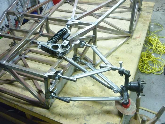
Here's all the components laid out ready to go. I need to spend about a day making a few more spacers then we should be able to get it rolling in
a day!
Ill get a peer to critique my load calculations and then i will post them up.
Thanks
Grant
[Edited on 7/7/11 by itsu-san]
coyoteboy - 7/7/11 at 02:47 PM
TBH I'm pretty damn impressed with the lot, while the arm issue could be a problem (we'll see with your maths) it isn't terminal - you
could re-create the bones later with smaller offsets and a more suitable bearing/bushing style if it did pose a problem.
Keep up the good work.
v8kid - 7/7/11 at 04:10 PM
Guys I really don't think there is a problem - race cars use 3/8" rod ends in the bottom lower outer wishbone and get away with it for a
while - but they do fail in that location.
Remember that by the time you get to the inner rod ends most of the forces have been divided by 2 or siphoned away by the springs.
Cheers!
coyoteboy - 8/7/11 at 09:29 AM
quote:
Guys I really don't think there is a problem - race cars use 3/8" rod ends in the bottom lower outer wishbone and get away with it for a
while - but they do fail in that location.
What race cars?
F1 cars often use mono-shock suspension, doesn't make it right for road use. And check out any decent rece vehicle and you will not find rod ends
on the lower outer joint at all. Hell, our student race team have a budget of 5K a year and don't use rod ends there on a car that weighs in sub
200kg!
[Edited on 8/7/11 by coyoteboy]
[Edited on 8/7/11 by coyoteboy]
v8kid - 8/7/11 at 11:33 AM
Err! Not sure how I've offended you but I thought that my previous post acknowledged that the bottom outer ball joint had already been recognised
as a high load item - that's why he has used a spherical joint to avoid the rod end shank bending entirely!
The race cars I see around me in the paddock have 3/8" spherical joints in other positions just go and look if you think I'm talking rot
Perhaps I read the post wrong but I thought that this was principally a track car and hence does not need to be over-engineered.
Cheers!
coyoteboy - 9/7/11 at 12:24 AM
You've not offended me, not sure why you think you have?
You said "race cars use 3/8" rod ends in the bottom lower outer wishbone and get away with it for a while"
I just wondered which ones (ie what series etc), I'd be surprised if any serious race team used rod ends in the bottom outer wishbone location,
hence the question. All the ones I've been around have either non-RE arrangements in all locations or load their rod ends solely in the axial
direction.
Don't think it's a matter of over-engineering, it's a matter of engineering.
[Edited on 9/7/11 by coyoteboy]
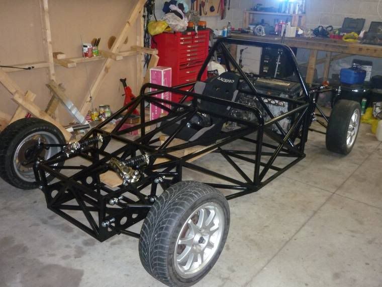
itsu-san - 20/7/11 at 04:24 AM
After two hard days finally got her off the table and sitting pretty!
[Edited on 20/7/11 by itsu-san]
iti_uk - 4/8/11 at 08:37 PM
Out of interest, did you do any FE analysis on the spaceframe? I'm concerned about the connection you have made between the front/rear boxes and
the central chassis. The bending stiffness of a chassis is dictated by transverse sections, of which the front/rear box connections
uneven/unprogressive geometry, and the torsional stiffness is dictated largely by joints, again the front/rear box joints look weak. Also, I'd be
concerned about anchoring your shocks on an un-triangulated cross-member. I'd expect to see deformation and therefore fatigue occurring around
that area. I'd second the comments made already about the wishbones. For an idea on how to have camber/castor adjustment on properly made
wishbones, have a look at how Mazda did it with the MX5 - bolts through slotted mounts located by eccentric washers. Very tidy.
All that said, good to see you're getting on well with the build. Should be one hell of a toy when it's finished.
Chris
itsu-san - 6/8/11 at 03:59 AM
Hi Chris,
Thanks for voicing your concerns but i can't say i share them.
I did not conduct a FEA study on the chassis as for my build i don't believe it was warrented. This chassis is compromised by cost and
construction techniques. The chassis has it's members aligned on flat planes and single angle cuts that have allowed me to construct it in my
garage without a complex jig or notching equipment. It is far from simple to "do FEA on a frame" and get useful answers. The chassis has
been designed to be safe and to be built in my garage with torsional stiffness a secondary concern and im willing to accept whatever weight i end up
with for this car.
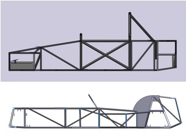
I have taken longitudinal profile of my chassis and compared it to that of your average 7 chassis. Just from visual inspection you can see my chassis
has a much higher second moment area and thus bending stiffness. Also keep in mind the chassis will be panneled with light gauge aluminium, further
resisting trapezing of those open profiles.
Chassis bending comparison
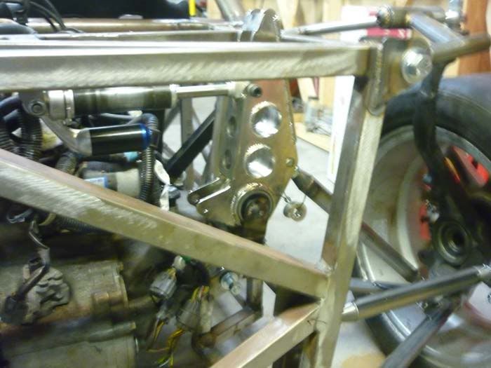
As for the shock mounts, im not sure what chassis you're looking at but the front shocks mount at point A in the picture below you can see the
load path here is well distributed. As for the rear shock mounts at B, again i cannot see you're problem with the load path. The mounts are well
triangulated and the loads are in tension and compression (generally).
Front and rear sections
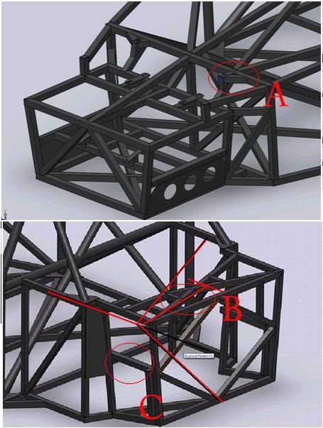
In case you were refering to the rocker mounting at C, thats a square cross section in bending and torsion. You can calculate the stress and it's
under the endurance limit for the chassis material (mild steel)
I personally don't like using eccentric sleeves for any kind of adjustment as i dont beleve these type of adjusters isolate the variables you are
trying to change well enough. Ie, you might be changing the static camber but you are also changing the roll centre height.
I've done the calculations for the rod ends in my suspension and im happy its going to be safe even though its not an optimal design.
Thanks
Grant
itsu-san - 17/8/11 at 11:36 PM
Got the chassis in etch primer and the suspension arms back from being powder coated.
Next up is extending the steering rack!
Doug68 - 20/8/11 at 09:07 AM
Hi Itsu san,
Looking at you frame again, at the rear of the car where I think iti_uk is refering to is below...
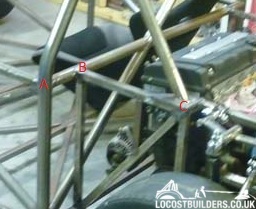
I think when loaded the member B-C will either be in tension or compression depending upon whats going on, this'll put member A thru B and on to
the other side in a bending condition. Which we all know is not good.
Another member from A to C would fix this, or if there's going to be a roll bar brace going forward this could probably achieve the same result.
itsu-san - 29/1/12 at 12:09 AM
itsu-san - 29/1/12 at 01:30 AM
Ivan - 29/1/12 at 09:10 AM
I know it looks better but why have you gone to the much more difficult to build compound curves on the wings from your initial design which I thought
was cool.
redbeard - 29/1/12 at 09:48 AM
Hi Great build
Curious what are the rear uprights from ?
Also like to oval rubes for wishbones - Wahat are sizes/ thickness