
Electric Reverse Trike - Build
ro - 26/12/15 at 05:52 PM
OK, so thanks to the help of the kind folk on this forum, I have a design for my electric reverse trike.
The design took place in a previous thread.
As a quick recap, this is what I'm building:
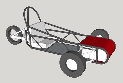
with a 30hp electric and 6x55ah SLA batteries.
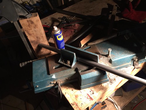
With a bit of time off for christmas, I started by setting up a very precise stop block on the bandsaw and cut all the tube to length
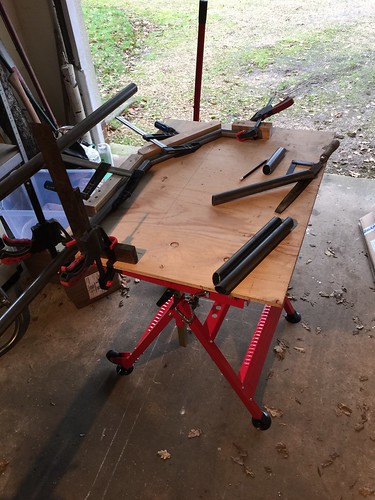
Next, I made up a quick jig for the rear end
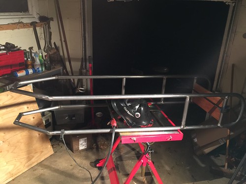
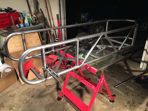
The initial welding went well and the chassis quickly started to take shape
At this point, I couldn't resist seeing if everything would fit
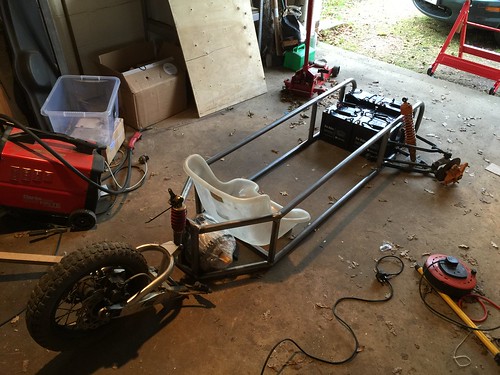
It all fits perfectly! And I can just fit into the go-kart seat (actually, I ended up sitting on the floor in it and making "vroom vroom"
noises)
Next I started tacking and welding the cross bracing in
Hopefully I'll finish off the chassis tomorrow and then it's on to fabricating the suspension mounts.
Thanks for looking!
v8kid - 26/12/15 at 08:40 PM
Looking good that's good progress!
Cheers
Benzine - 26/12/15 at 08:47 PM
this is relevant to my interests 
What front suspension and wheels are you going to be using?
ro - 27/12/15 at 09:25 AM
quote:
Originally posted by Benzine What front suspension and wheels are you going to be using?
The three main goals for this project are: simple, efficient, and simple!
So, in line with that I bought some old double wishbone quad bike suspension off eBay and am mating that to some 145r10 trailer wheels.
The joy is that everything is so simple that, once it is up and running it should be easy to modify or swap any component out if I want to change the
design.
[Edited on 27/12/15 by ro]
v8kid - 28/12/15 at 04:59 PM
Brand new electric motor? Were is it from and what controller are you thinking of using? I guess the starting current is somewhere around 1000A at
36V?
Cheers!
ro - 28/12/15 at 06:39 PM
quote:
Originally posted by v8kid Brand new electric motor? Were is it from and what controller are you thinking of using? I guess the starting
current is somewhere around 1000A at 36V?
I ordered a new Motenergy ME1003 and Alltrax SPM72400 from an American eBay seller. I could not find anywhere in the UK/Europe that sold them for a
decent price - even with shipping and import tax it was cheaper to buy from the States!
The starting current should be around 400A @ 72V which the controller should cope with fine, but I've specced the wiring for 1000A so I can
upgrade the controller if I feel the need.
ro - 28/12/15 at 07:00 PM
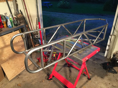
OK, so I got a couple of hours this afternoon to mess around in the workshop.
Finished off the chassis bracing. It's really starting to feel like it might work now!
Next, I decided to make a start on the front lower suspension mounts as I had no idea how to make them - the bottom of them needs to mate exactly to
the 32mm tube that makes up the chassis.
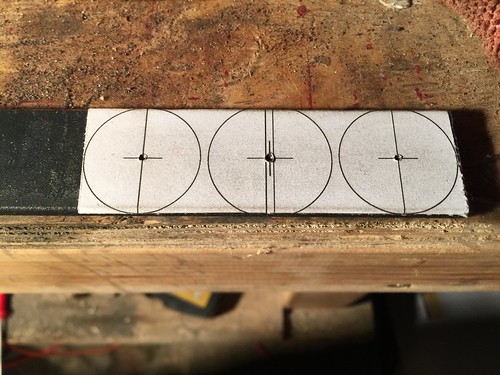
After a couple of false starts and utter cock ups, this it what I came up with:
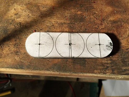
I made up a quick template on the computer and printed it off, stuck it onto a length of 30mm flat stock and centerpunched the holes
I then roughly cut it out on the bandsaw and shaped it on the belt grinder
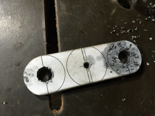
Drilled the holes for the suspension mounts @ 10.5mm and a pilot hole in the middle @ 3.5mm
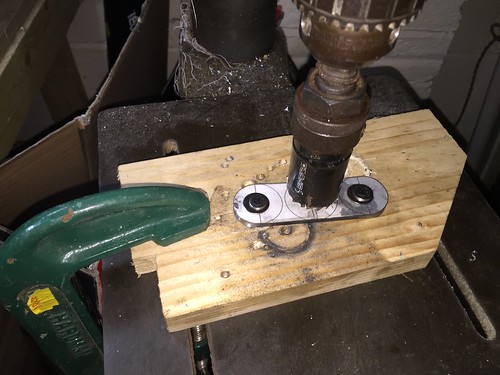
The holes for the suspension mounts were then used to fix it to a piece of wood which I then clamped to the table of the pillar drill
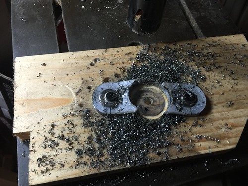
I then used a 32mm hole saw to cut out the middle section.
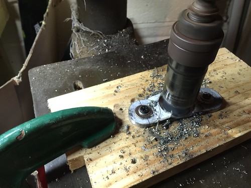
The hole saw cut the steel much better than I thought it would. Lowest speed on the drill and copious amounts of WD40. I was left with 2 almost
finished suspension mounts!
A little tidying up with a file and the belt grinder left me with 2 perfect little suspension mounts 

Now I just have to make 6 more and weld them in place...
[Edited on 28/12/15 by ro]
ro - 29/12/15 at 06:33 PM
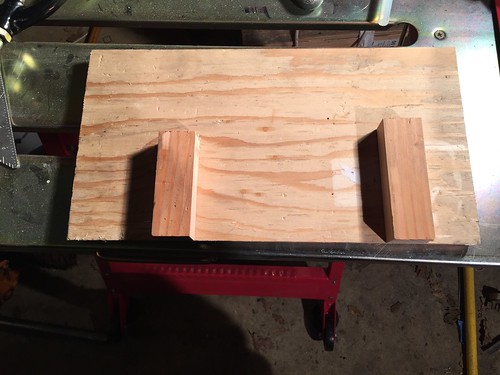
OK, so I had to weld on the suspension mounts. Obviously they need to be aligned quite accurately, so I started by making up a quick alignment jig out
of offcuts and hot glue
Clamped it onto the frame, using the bottom of the blocks to align it against the bottom tube and a 25mm spacer between the front block and the front
upright tube
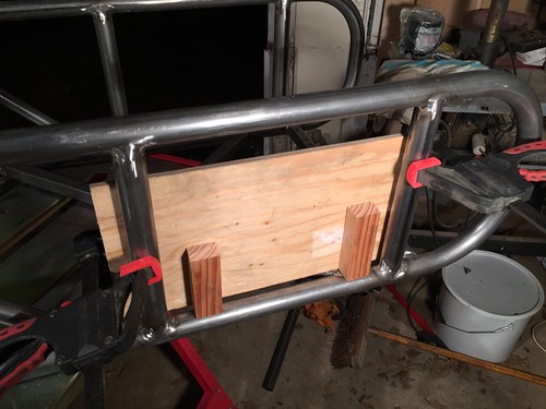
then clamped the mounts either side of the blocks and pushed them back against the board and tacked them in place

A quick check with one of the wishbones shows it worked just fine!
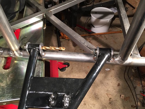
Thanks for looking! Hopefully I'll get onto the top mounts tomorrow.
v8kid - 9/2/16 at 10:07 AM
Hi how's progress?
Cheers!
ro - 10/2/16 at 01:40 PM
quote:
Originally posted by v8kid
Hi how's progress?
Thanks for the interest!
Progress has stalled slightly as, once I got the suspension on, I realised that the uprights and hubs I was planning to use were not going to be man
enough.
So, I am now going to use MX5 uprights which means that I am having to modify the wishbones to take different balljoints/steering geometries.
I've finished the planning of this and work starts again this weekend - expect more updates soon