JoelP
|
| posted on 12/7/07 at 08:17 PM |

|
|
ah there is that, thats down to the material of the main body though. Recently it was pointed out that overtightening the locknut can cause it to
sheer at the threads. 1/2" is a pretty meaty shaft to snap though!
I have a bag full of m10s! 
|
|
|
|
|
ChrisGamlin
|
| posted on 12/7/07 at 08:34 PM |
|
|
Given the fact that a Chinese minister has just been executed for allowing lethal medicines to find their way into the supply chains, do you trust
them to ensure that £4 rod ends are consistently made from the correct grade of metal? 
|
|
|
Alan B
|
| posted on 12/7/07 at 08:43 PM |
|
|
quote:
Originally posted by ChrisGamlin
Given the fact that a Chinese minister has just been executed for allowing lethal medicines to find their way into the supply chains, do you trust
them to ensure that £4 rod ends are consistently made from the correct grade of metal?
I do now.....LOL..
|
|
|
ChrisGamlin
|
| posted on 12/7/07 at 09:01 PM |
|
|
Wont make that "mistake" again I guess
|
|
|
nitram38
|
| posted on 12/7/07 at 09:13 PM |
|
|
quote:
Originally posted by RazMan
Have you got any detail pics of the Atom? I would be interested to see what they do with the front uprights. (Google doesn't come up with much)
Goto www.atomclub.com
I think that using anything under 1/2" unf is madness, but I have not have a ball come out of the rod end on an 800kg car.
If it does then the washer will stop it parting company. I always check the rod ends before setting off. There has not been any sign of them
loosening up or bending. I also have kept them wound in so the thread showing is as short as possible. Again less chance of bending.
One other thing to consider is the length of my wishbones. On a 7 there is probably more force generated on a rod end because the bones are short
whereas some of the bump is absorbed by longer bones and hence less suspension travel.
The other factor is my suspension does not travel as far as a 7 over the same bump. Longer bones mean a longer arc, so they tend not to move as much
(hope that makes sense?).
Atom Front Suspension:
 
Description
Raceleda setup:
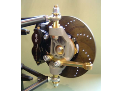 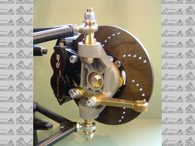
Description
[Edited on 12/7/2007 by nitram38]

|
|
|
RazMan
|
| posted on 12/7/07 at 09:36 PM |
|
|
I stand corrected regarding application then - if Aerial consider a rod end to be safe on an Atom then an ultra lightweight car like yours should be
also, although I still wouldn't be happy with that setup on my own car (800kg) Without wishing to labour a point though, do you know the spec of
their rod end? Betcha it costs more than £4 
[Edited on 12-7-07 by RazMan]
Cheers,
Raz
When thinking outside the box doesn't work any more, it's time to build a new box
|
|
|
Fred W B
|
| posted on 13/7/07 at 01:17 AM |
|
|
Im planning to just use M16 rod ends at the front upright end and be done with it
So far I've just bought branded SKF "industry std" parts, and will replace with better if needed.
Photo is of a very rough mock up while experimenting with front upright geometry
Cheers
Fred W B
 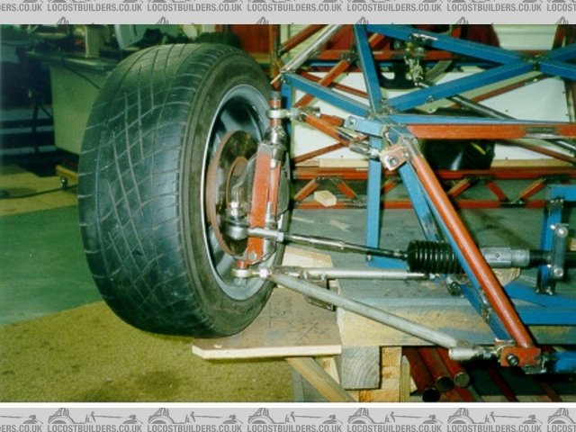
Front suspension mock up
[Edited on 13/7/07 by Fred W B]
|
|
|
ERP
|
| posted on 13/7/07 at 01:49 AM |
|
|
Apparently it's not all that uncommon for rod ends to fail on the Atom.
http://forum.atomclub.com/index.php/topic,1707.0.html
|
|
|
nitram38
|
| posted on 13/7/07 at 03:13 AM |
|
|
quote:
Originally posted by RazMan
I stand corrected regarding application then - if Aerial consider a rod end to be safe on an Atom then an ultra lightweight car like yours should be
also, although I still wouldn't be happy with that setup on my own car (800kg) Without wishing to labour a point though, do you know the spec of
their rod end? Betcha it costs more than £4
[Edited on 12-7-07 by RazMan]
Self tappers cost £4 each on an atom!!!
As for rod end failure on atoms, you will also find that a lot of atom drivers have more money than sense and drive their cars to destruction without
checking anything.
As for the article you suggest, it was a rod end that was working in the so called correct way but if you read it again, you will find
that this item was undersized for the use it was designed for and has since been resized to a larger one from 10mm to 1/2".
Like earlier posts, rod ends are ok if they are big enough.
[Edited on 13/7/2007 by nitram38]
|
|
|
RazMan
|
| posted on 13/7/07 at 07:35 AM |
|
|
Actually, reading through that thread, it appears that many owners are replacing all of the rod ends on their car after only a few thousand miles
(presumably on smooth racing circuits) and Aerial themselves recommend 'competition grade' rod ends for safety.
Quote from the thread "I'll be opting for those kevlar lined Heims, at least for those 2, and the 2 on the front. They are however
expensive...."
At least I have only got four to replace
[Edited on 13-7-07 by RazMan]
Cheers,
Raz
When thinking outside the box doesn't work any more, it's time to build a new box
|
|
|
Doug68
|
| posted on 14/7/07 at 01:41 PM |
|
|
I've also been shown these (see picture).
Which apparently are used in dragsters for something.
Anyhow they look darn near perfect for the application I need them for if a bit over sized being 3/4" UNC thread with a 5/8" hole.
They came from here but I'm sure there must be other suppliers of the things.
 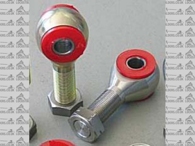
Rescued attachment rodends1.jpg
|
|
|
Peteff
|
| posted on 14/7/07 at 03:20 PM |
|
|
Top ball joints on our cars are not really designed for what we use them for either, they are drag link couplings from an antique steering system used
on goods delivery vehicles. Some people say the range of motion on them is inadequate but we keep using them mostly without any problems (because they
are 18mm thick probably explains that though)
yours, Pete
I went into the RSPCA office the other day. It was so small you could hardly swing a cat in there.
|
|
|
MikeRJ
|
| posted on 14/7/07 at 08:09 PM |
|
|
quote:
Originally posted by Peteff
Top ball joints on our cars are not really designed for what we use them for either, they are drag link couplings from an antique steering system used
on goods delivery vehicles.
They are also used on the much more lightly loaded top arm. Some kit cars have used them with rocker arm designs though, which is particularly poor
engineering IMO. Ignoring the stresses on the threaded section which will probably have little safetly margin, putting forces axialy down the taper
into the ball joint will cause the spring inside to compress and suddenly your nice tight ball joint becomes very sloppy.
|
|
|
RazMan
|
| posted on 14/7/07 at 09:58 PM |
|
|
quote:
Originally posted by Doug68
I've also been shown these (see picture).
Which apparently are used in dragsters for something.
Anyhow they look darn near perfect for the application I need them for if a bit over sized being 3/4" UNC thread with a 5/8" hole.
They came from here but I'm sure there must be other suppliers of the things.
Don't they look good! - a sort of cross breed between a poly bush and a rod end. I think they would be ideal for a wishbone setup, quieter and
more resilient than rod ends. Shame they don't do smaller sizes though.
Cheers,
Raz
When thinking outside the box doesn't work any more, it's time to build a new box
|
|
|
Uphill Racer
|
| posted on 14/7/07 at 11:03 PM |
|
|
Have used 1/2" rose joints on front uprights like that for over 10yr, but on a car that is under 800lbs. The design and chassis pick up points
(inboard whishbone) need to be well positioned. So as the rose joint can be fitted with the maximum (under 1/4" of thread outside of locknut.
Single shear is a killer. IMHO
http://s72.photobucket.com/albums/i187/uphill-racer/?action=view¤t=Fupright.jpg
|
|
|
rally design
|
| posted on 16/7/07 at 11:55 AM |
|
|
Use of Rod Ends at top of front upright
I don't normally get involved in discussions on this website,because I think the strengths of the locost principle is that members should be
allowed to freely evolve design's which are of their own creation and thus a succesfull outcome rewards satisfaction of doing 'their own
thing'.
However I feel it is important to make some input where I consider 'life or death' parts are being compromised.
I can understand why a rod end would be utilised in the orientation shown in 'nitram 38' photos-it is easy to engineer ,the mount bolt or
pin is directly into the top of the upright and the threaded stem presents itself nicely to a female threaded tube in the wishbone.
This system is often used in race car construction but it is important to understand the type of loads involved and a good race car designer will have
appreciation of the compromises.
Rod Ends(not allowed to call them rose joints any more for fear of breach of trading style)are strongest where the load is perfectly radial,ie where
the load is parallel to the line of the stem such as in a 4-link system.
If the rod end is turned such that the major loading is now axial then the failure load is reduced by a factor of 10.The rod ends shown in Nicam 38
photos are of the inexpensive pressed construction type which have a U.S.R.L (Ultimate static radial load)of about 8,500 lbs - if this rod end is
loaded fully axially(sideways)then the load figure is only 850lbs.
Mention of safety washers is somewhat academic,these rod ends rarely fail due to ball pull out or bolt failure,unless the rod end selected is of too
small size.They normally fail at the root of the stub thread.
The risk of failure is almost inevitable when the rod end has insufficient angle of misalignment to cope with the range of suspension movement...this
is more critical on a road car than a race car because of the greater range of movement required.Designers utilise tapered side spacers so that the
head of the rod end has the greatest range before lock out occurs.Ironically the cheap pressed construction joints have a greater angle of
misalingment(average 20%)than the 3-piece race quality joints(average 12%)though expensive high angle joints are available.
With use of hard shocks and stiff springs the risk of rod end failure is increased because the acceleration of the upright on bump can exceed the
acceleration of the wishbone.this is particularly true when the shocker is mounted well inboard from the upright.
We have been involved with 2 major racecar manufacturers (who both should know better)who experienced lock out of the top rod end ,both experienced
bearing failures of this joint on primary laps of prototype testing.Both used the best quality rod ends from respected suppliers so it wasn't
poor quality product.
In both cases the designers had incorrectly calculated angles of misaligment causing lock out on maximum bump and also the shock loading figures on
hitting race track bumps.
Both resorted to rod ends with 1" stubs and taper spacers to increase angle of misalignment,this cured the problem.
For road use I personally would use the Transit drag link at the top of the upright and Maxi type ball joint at the bottom of the upright.The Transit
drag link has a strong M18 stub,is stress relieved to avoid stress concentration at the thread root,has 20 degree misaligment angle.is fully dust
shielded and is cheap.
Similarly the Maxi ball joint is specifically designed to accept high axial loads and again 20 degree misalignment angle.
Also I would question use of rod ends on the inboard ends of the wishbones,PTFE bushes with stainless tubes will have a much greater life.
Hope this helps.
David Elderfield
Senior designer
Rally Design Ltd
|
|
|
RazMan
|
| posted on 16/7/07 at 12:58 PM |
|
|
David, thankyou for input. I am sure that your advice will save some builders from premature suspension failure with potentially disastrous results.

Cheers,
Raz
When thinking outside the box doesn't work any more, it's time to build a new box
|
|
|
nitram38
|
| posted on 16/7/07 at 01:03 PM |
|
|
I should have added to all my posts, that on my car, the engine is at the rear, so less load on my rod ends.
If you are saying that my cheaper "pressed" rod ends do not fail with the ball coming out, then is is just a small rod diameter that is
the problem.
If you look closer to my photos you will see angled spacer washers so the rod ends don't bottom out.
|
|
|
Doug68
|
| posted on 16/7/07 at 02:56 PM |
|
|
Nitram 38 what do you estimate the loads are in this joint on your car?
My guesses would be 20kg for the unsprung mass and 40g for the bump (anyone have better data?) giving a force of 800kg.
I'd guess that there's ~40mm of distance between the thread emerging from the tube and the center of the ball, therefore thats 32kgf-m
(230ft-lb) of bending torque on the rod end.
Would you agree or not?
Do you think this sort of loading is acceptable for the component you are using?
Notice the mass of the vehicle doesn't come into the calc as its the wheel (unsprung mass )that goes over the bump and its the wheel that needs
to be controlled by the spring - damper.
|
|
|
nitram38
|
| posted on 16/7/07 at 03:08 PM |
|
|
I am basing my design on the Aerial atom, not by calculations. They use this set up and same size rod ends, except my car is lighter than theirs.
Do your calcs take into account length of wishbone?
The load you talk of, changes depending on the length of the bones too, as the bending moment is not 40mm as you suggest.
The load is spread the entire length and not focused at this point.
I have seen more broken wishbones than rod ends.
Perhaps you had better talk to Ariel and Raceleda too ?
[img][/img]
Description
[Edited on 16/7/2007 by nitram38]
|
|
|
JoelP
|
| posted on 16/7/07 at 03:46 PM |
|
|
Lets do some sums for the fun of it, i'll start, feel free to refine if you like.
What loads would we expect the car to withstand? If i drove into a kerb at say 40mph id expect something to break or the tyre to blow out, so lets
assume worst instant loading will be a 3" kerb at 40mph. These figures wont be precise because i intend to guestimate them.
a wheel with a diametre of 20" would hit a 3" kerb approximately 6" infront of the axle centre. Hence the wheel would lift 3"
over a distance of 6". We'll assume a linear rise, even though it wont be exactly.
6" at 40mph is travelled in (17m/s over 150mm) is roughly 0.01 seconds.
Speed the wheel rises is thus 75mm in 0.01 seconds
(im thinking at this point the tyre would probably pop, but i'll go on anyway...)
this is 0.075m in 0.01 secs, or 7.5m/s. To reach a speed of 7.5m/s in 0.01 secs is 750m/s/s, or roughly 75g.
Doug, i assume you discount the weight of the car because the spring allows it not to move? Im thinking it must be more complex than just that,
because that wouldnt take account of spring stiffness - if it was very stiff the car would have to move too, increasing loading etc. I suppose any
spring would compress under that load so however stiff it was the car couldnt raise that fast without breaking something.
Anyway, at best unsprung mass will be 15kgs per corner, so by your method loading would be 1200kgs. I must say im not convinced you can just multiply
the g force by the weight, wouldnt that be the force that the kerb feels?
|
|
|
Mave
|
| posted on 16/7/07 at 08:33 PM |
|
|
Brammo, the US manufacturer of the Ariel, seem to have changed their bottom balljoints, as seen in this picture. I don't know if that has
anything to do with the rod ends.

|
|
|
nitram38
|
| posted on 16/7/07 at 09:51 PM |
|
|
For anyone who doubts the quality of McGill Motorsports rod ends, here is the spec and they are only £2.23 each plus £0.75 delivery:
CML 8 (1/2 X 1/2 UNF ) Rose Joint Materials Specification ;-
Ball
52100 Bearing Steel
Heat Treated.
Hard Chrome Plated
Precision Ground
Body
Carbon Steel
Protective Coated for Corrosion Resistance
Exclusive Features
Maintenance Free.
No problems of PTFE Liners popping out under high loads.
Radial Static Load Specification
12,224 Pounds
I think that these are over the 8500lbs calculation already stated and the LACK of a ptfe liner is better than buying ones with.
Mcgills ebay shop NTDWM
[Edited on 16/7/2007 by nitram38]
|
|
|
Doug68
|
| posted on 17/7/07 at 01:07 AM |
|
|
The 40g loading used comes from conversations with I've had with a professional vehicle testing engineer, and is based upon real recorded
vehicle test data. It is severe loading but it is not crash level loading.
Nitram 38, think about the path the load has to take from the tyre contact patch to the suspension mounting point on the bottom wishbone as far as I
call tell the length of the wishbone has nothing to do with it.
Other people have based designs on the Atom on the mid-engine forum there's a guy who did just that and suffered rod end failure from supposedly
good quality items. Thankfully he was at the track and no one got hurt.
Anyway I think the point has been made. Please think really carefully about what you're doing I want to see pictures of you driving your
finished car around and not of a mangled mess after one of the wheels came off.
[Edited on 17/7/07 by Doug68]
|
|
|
Hammerhead
|
| posted on 17/7/07 at 12:54 PM |
|
|
Martin, I think that Marcel (Mave) made a very useful point by showing the brammo version of the Atom wishbones.
I don't know if the changes were made for cost, weight or safety reasons, but surely it's worth investigating further.
How about contacting brammo in the US and asking the reason for the difference.
I think people are trying to help you design a safe car, not trying to undermine your concept in any way. Do Is it really that bad to make new or
adapted wishbones?
Still very much looking forward to the results.
|
|
|