
I'm using the 01X transaxle from a front wheel drive Audi in my mid-engined rear wheel drive car.
Everything's going fine, but I'm getting to the stage where I have to start considering my linkage.
I have the linkage / shift-stick assembly for the box, but obviously everything will need to be reversed for my application.
Has anyone done this that can offer some tips?
Here's a couple of pics of the linkage in its normal configuration... is it simply a case of employing new rod lengths and shaping them to travel
round either side of the engine?
Normal Configuration
Close Up
this may help
Cheers
Fred W B
I've been thinking about this subject a lot, especially as if a solution can be found it will be of use in my next buggy project. This is where
I've got to so far-
The key to the solution lies in the gear change lever and housing. I am thinking along the lines of constructing a new unit which would be applicable
to virtually any remote gear changing situation, and which would operate by means of cables.
A conventional gear change mechanism produces two motions, side to side and backwards/forwards. This information could be converyed to the gearbox by
two bowden cables, and converted there into whatever motion was required.
The gearchange lever and housing could have a gate CNC cut into the top of the box, through which the gear lever would protrude. The two control
motions could be transferred to the cables by bell cranks, the lengths of which could be varied to suit the motion required at the gearbox.
The visible gate would be useful, and it would be easy to incorporate a reverse detent
I can see it in my mind's eye, but the attempts I have made so far at sketches have not been so good.
John
What, like this unit from http://www.renegadehybrids.com/?

quote:
Originally posted by TheGecko
What, like this unit from http://www.renegadehybrids.com/?
I like the look of that, but agree on the price!
Anyhoo... getting back to the original question (ahem!) - what doth the masses think about reversing the assembly in the picture (obviously with
re-shaped / lengthened rods)?
I only ask as the gear-shifter unit cost £30 and it's OEM 
Right, I've been thinking about this some more, and have come up with the definitive locost solution
So, for the application in question-
Find a reasonably modern front wheel drive car with the same shift pattern as the Audi box, but with cable change (lots of cars have these, Mondeos,
Audi transverse FWD)
Then, get the shifter from such a car and see if it can be set up so the cables exit the back of the shifter rather than the front. If not, which is
likely, then you will need to make a reversing unit which can be done with a couple of 180 bellcranks.
The specially made cables can then be run back to the gearbox (right hand gear change feasible this way) and the cables can terminate at brackets
mounted on the gearbox, and the correct motion can then be appied to the selectors by fitting new bellcranks or terminations as required (I don't
know what's required for that box, but once the control movement is present at the cable end it can be converted to whatever is needed)
John
Morse Cables, the people who make the push pull cables, used to sell a gearchange setup just like the one in the pic. Originally used in roadgoing
GT40's, way back when, and adapted by a couple of big names makers over recent times.
Don't know if they still do though.
Cheers,
Syd.
Scootz, morse cable work ok but dont give you the feel of a direct linkage. you can use the system i have on my subby box , it has been used on Audi
boxes before and is very simple to make

cheers Kaspa
quote:
Originally posted by Kaspa
Scootz, morse cable work ok but dont give you the feel of a direct linkage. you can use the system i have on my subby box , it has been used on Audi boxes before and is very simple to make
cheers Kaspa
My dear sir all you have to do is ask, although if you look at the pic its all prety self explanetry.
its just a rod mounted on a spherical bearing at the front with a tube slidig over it controled by the lever to give fore and aft movement , and it
swivels on its own axis on the forward rod. the conection to the trans would be a simple lever with the control rod mounted firmly in a bearing to
allow forward ,aft movement and rotation.
have a look here to how i have done it with the subby box
http://s236.photobucket.com/albums/ff257/stryka_01/Stanton%20WRC-95/
cheers kaspa
quote:
Originally posted by Kaspa
My dear sir all you have to do is ask, although if you look at the pic its all prety self explanetry.
Right... I'm heading out to the garage to conduct an experiment... I may be some time!
Phew... back again (and I only lost the one eye!).
I should be able to use a single rod linkage similar to Kaspa's in the cockpit, together with the (modified) ball-joint set up at the
gearbox-end.
Will hopefully have done a mock-up by the end of the week and will post some pics!
Scootz if yo have a look at some of the threads on GT40s.com forum youll see how the same system is used on there cars, with the lever in both center
and side position, on Audi boxes.its real easy to do.
cheers Kaspa
Cheers... I basically aim to turn the ball joint assembly upside down and back to front!
Your onto it, if you want some pics of the lever arrangement, ill pull it apart on the weekend and take some pics for you, its only 3 peices.
cheers Kaspa
quote:
Originally posted by scootz
Phew... back again (and I only lost the one eye!).
I should be able to use a single rod linkage similar to Kaspa's in the cockpit, together with the (modified) ball-joint set up at the gearbox-end.
Will hopefully have done a mock-up by the end of the week and will post some pics!
Will be running it centrally Mr H.
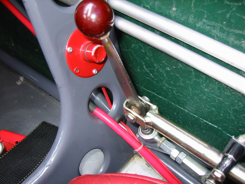
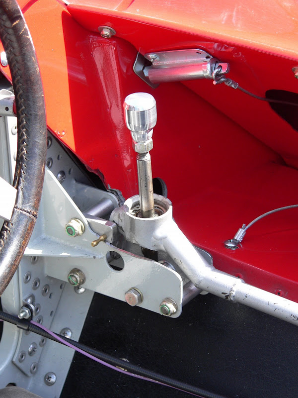
To add some variety to the discussion, here's a pair of Lotus shifters - a Lotus 18 and a 30 respectively.


Hope this is helpful,
Dominic
It's not the shifter that's the problem, it's transferring the motion the shifter generates to the selector on the gearbox.
Now it would be good if Scootz would confirm this, but it seems to me that the selector on the gearbox is on the left hand side and enters the gearbox
at right angles to the centreline of the car.
What I am trying to 'get my head round' is how that gearchange motion can be transferred to the gearbox selector using rods, and especially
from a position in the middle of the car. Now I am sure that doing such a thing is possible, for instance bicycles from many years ago had rod brake
linkages to the front wheel, but I look forward to seeing how it can be done in this case more simply than by using cables.
John
quote:
Originally posted by mr hendersonNow it would be good if Scootz would confirm this, but it seems to me that the selector on the gearbox is on the left hand side and enters the gearbox at right angles to the centreline of the car.
This PIC HERE may help out... it's the 'ball-joint' that
attached to the gear actuator (box end).
The D-shaped section is attached to the bottom of the ball joint and slides onto the actuator.
The rod is attached to the top side of the ball joint.
Basically, whenever you push /pull the rod, it turns the actuator in that direction. If you twist the rod, the actuator will move side to side.
It's just a case of joining rods that lead to the gearstick with steering-type joints, so that there can be some changes in direction /
elevation.
Essentially, whatever movement you make on the gearstick 'rod', it is replicated at the ball-joint end.
Hope this makes sense (not sure that it does...  ).
).
quote:
Originally posted by scootz
Hope this makes sense (not sure that it does...).
Hi Henderson - The pics in the thread I linked to in the second post on this thred may help.
basically moving the gearlever left right moves the selector in and out of the box, while forward / aft is obvious.
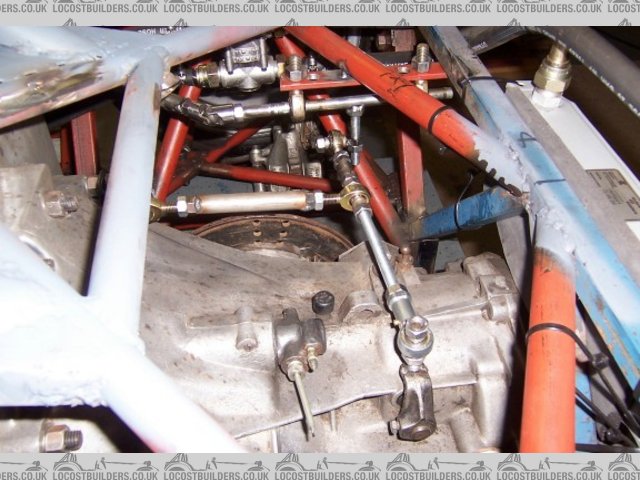
This is development rough work, the real thing will be much neater
Cheers
Fred W B


links rear
[Edited on 13/8/08 by Fred W B]
[Edited on 13/8/08 by Fred W B]
Well, I'll be interested to see pics of both finished versions eventually, but I must say, that, in my own personal opinion only, that they seem
like a lot of work and materials compared to the cable option.
John
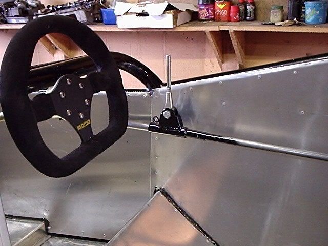
The 'cockpit rod' will simply be a straight rod held at both ends by a rose joint, so that it can slide back and forth, and side to side.
Towards the front of this 'cockpit rod' (about 20cm back) there will be a shorter rod welded at a right angle and pointing up. This will
be the gearstick.
The 'intermediate rod' is connected to the 'cockpit rod' and 'gearbox rod' with steering couplings and is also held at
both ends by rose joints attached to lower chassis rails.
Finally, the 'gearbox rod' (with ball joint at mid point) is held at both ends by rose joints attached to upper chassis rails.
Because all fronts / ends of rod sections are hard fastened in place, the movement at the gear stick will be replicated throughout.
If you look at this picture of a Spyker gearstick, it
will give you some idea (but delete the lower rod as I won't be using one).
I too had thought about cables, but I have most of the component parts at hand for the rod assembly, so I'm going that route. I couldn't
figure how to control the cables at the gearstick end.
So presumably the gearbox/engine assembly will be rigidly, or at least extremely stiffly mounted to the chassis? (in order to prevent unwanted
selector movement during acceleration and braking)
Jon
Yep... my mounts will be somewhat agricultural in design! 