
ZX10R turbo engine rebuild and baffled sump fabrication
SausageArm - 24/4/12 at 08:08 PM
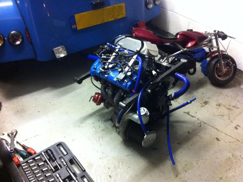
Here we have one poorly sounding ZX10R turbo engine 
Oil drained and engine was turned upside down and the sump removed, some metallic particles were found in the sump
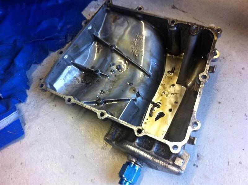
More metallic particles evident on the sump gasket

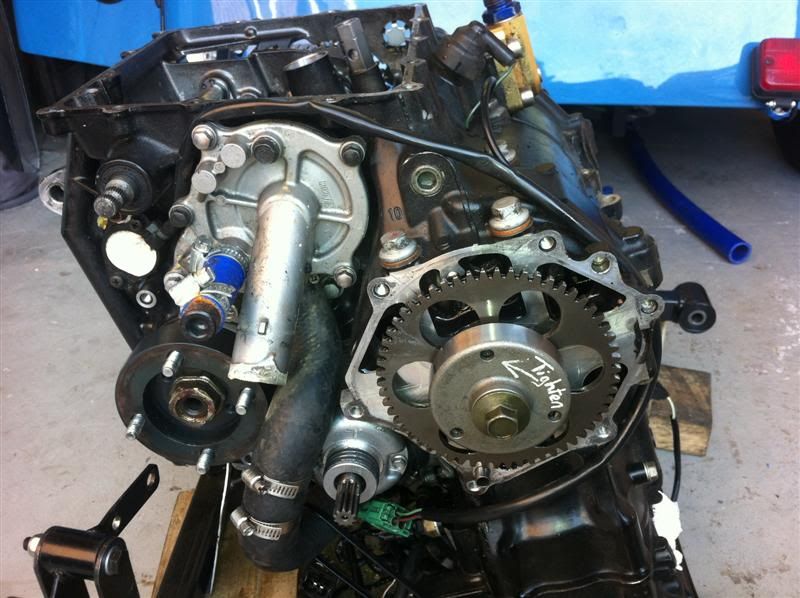
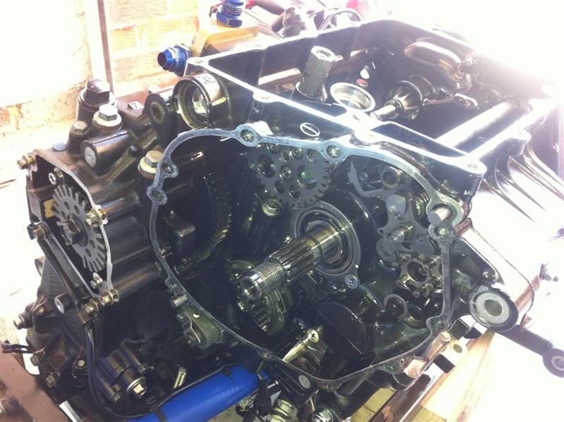
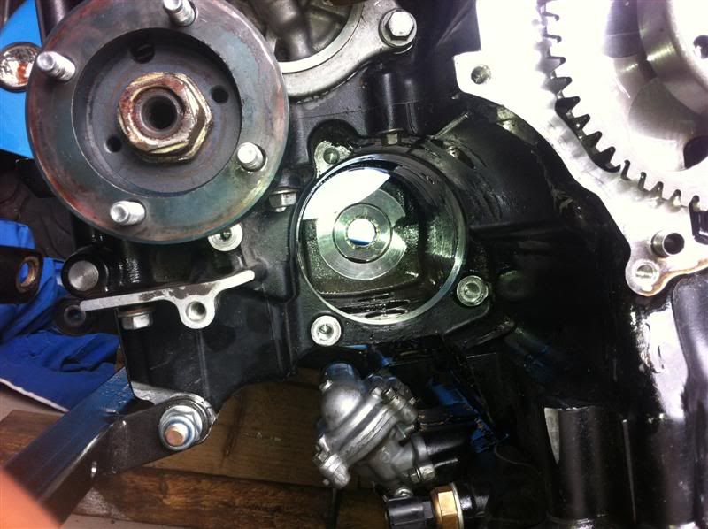
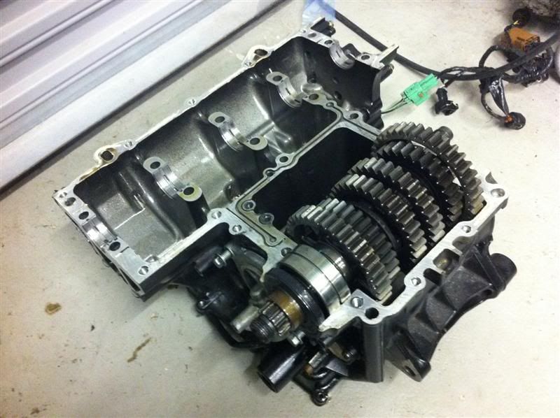
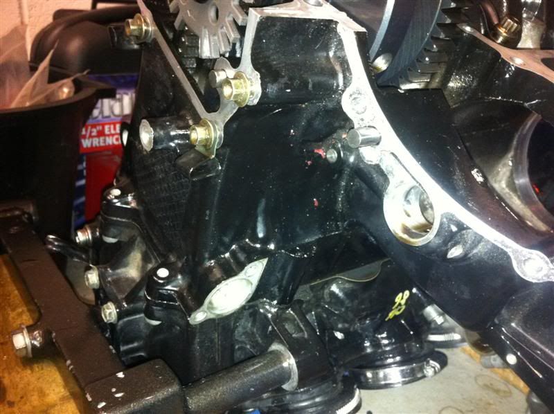
With the oil pickup and clutch cover removed the engine looks like this

Removed the covers and idler gear from the starter motor assembly
Crank position sensor cover and clutch plates removed
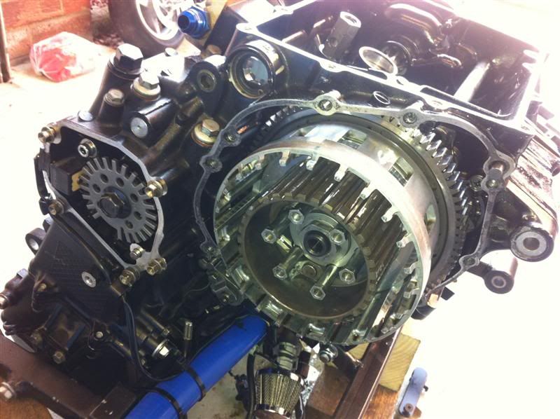
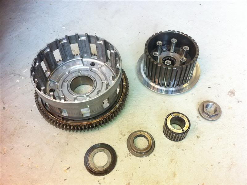
Clutch basket taken off
Clutch basket assembly
Remove this circlip from the gear selector shaft, then it can be slid out of the transmission casing

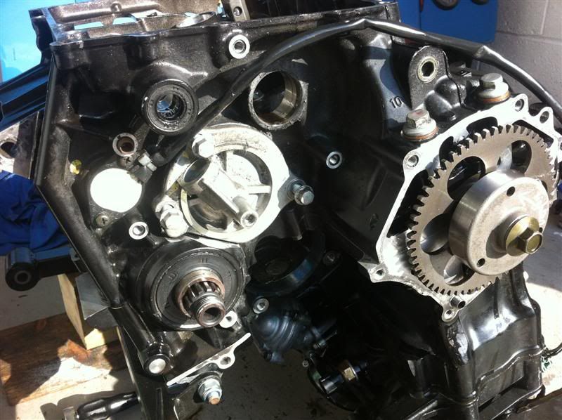
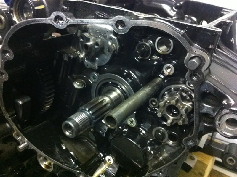
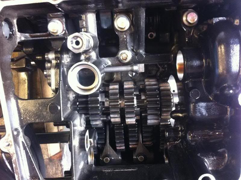
With the selector shaft removed, things look like this inside


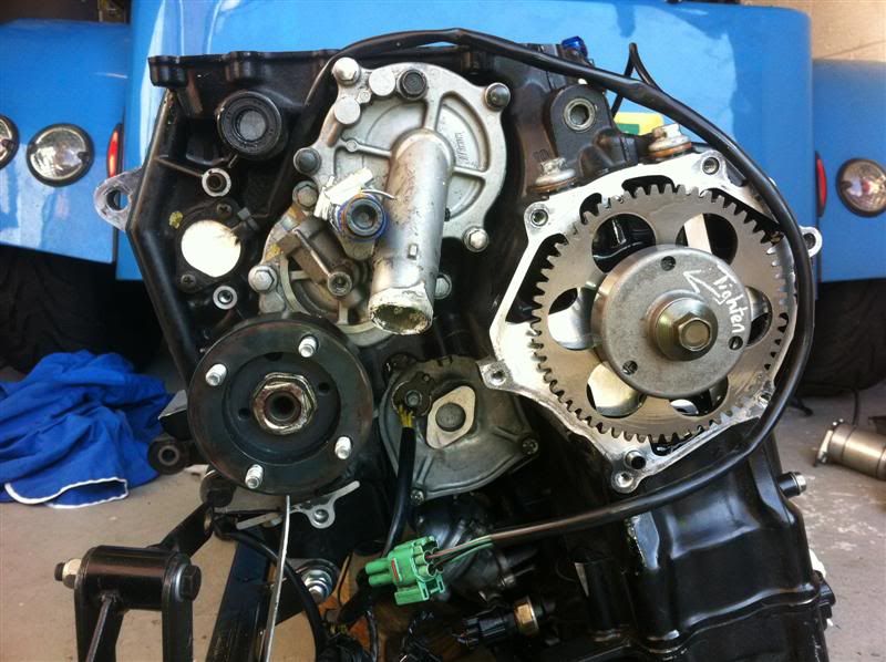
Starter motor removed which gives access to the generator cover
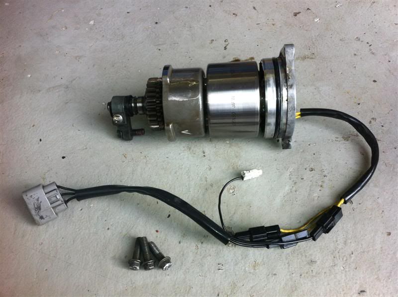
Generator assembly removed
Big hole where the generator lives
Sprocket adaptor and water pump removed
Oil pump drive gear removed
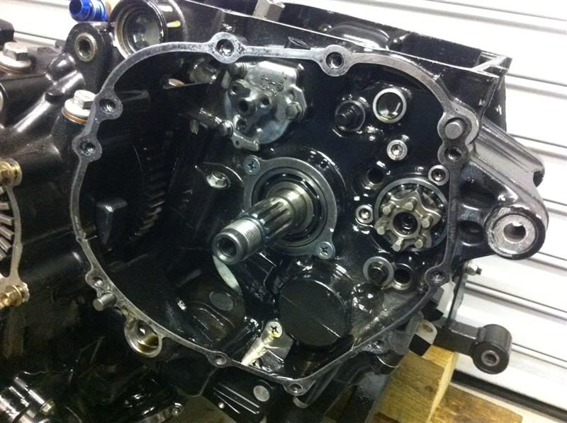
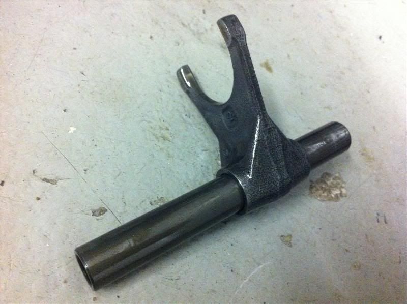
Lower gear selector fork shaft being withdrawn

Lower selector and shaft
[Edited on 24/4/12 by SausageArm]
SausageArm - 24/4/12 at 08:10 PM
Upper selector fork shaft being withdrawn
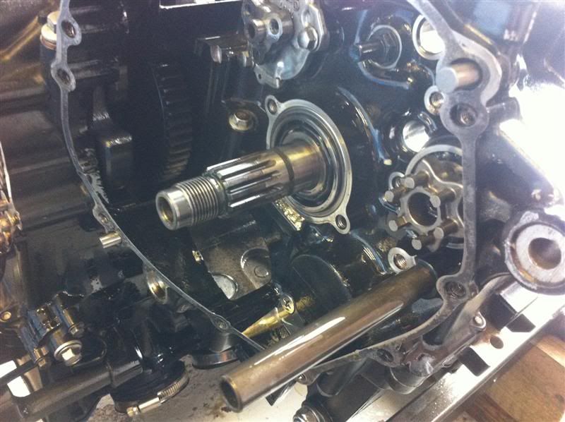
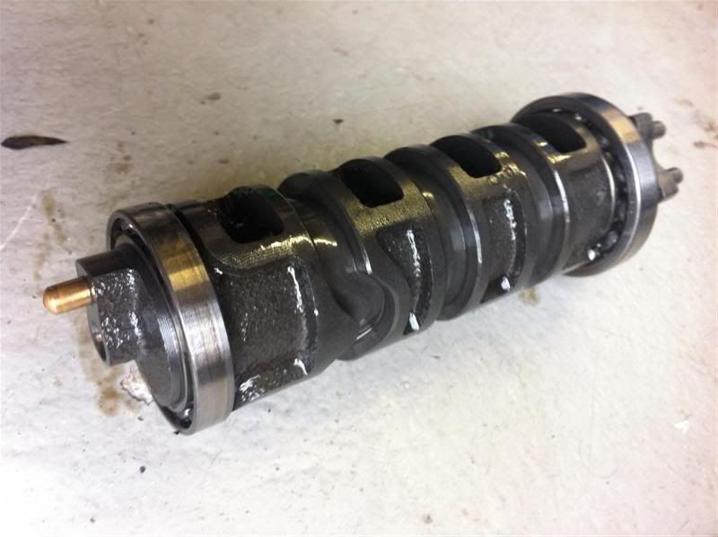
Gear selector drum being withdrawn

Gear selector drum assembly
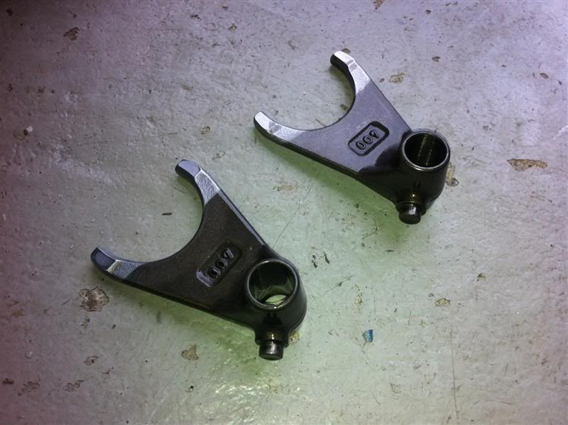
Selector fork shafts and drum removed but upper selector forks still in position
Upper selector forks
Oil pump
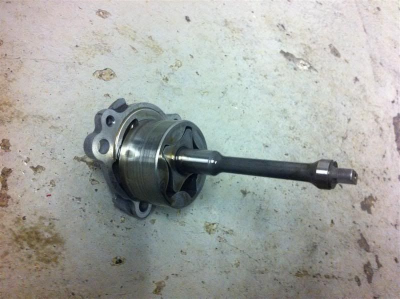
Oil pump housing

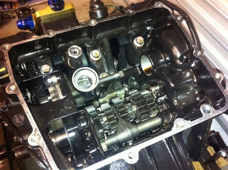
Engine casing split and the transmission removed
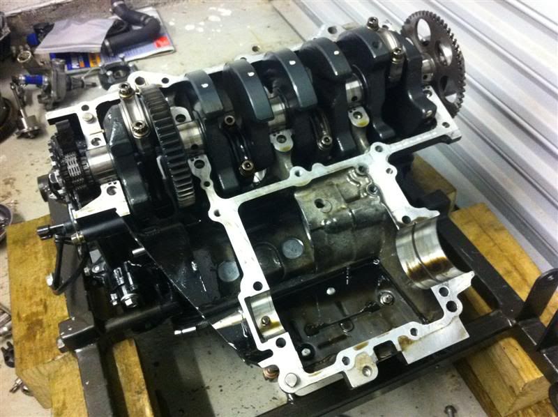
Transmission
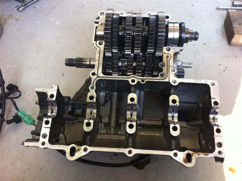
Transmission output shaft removed

Transmission shafts

Having got to this stage of the stripdown and not found anything obvious wrong I was getting a bit concerned, due the large pieces of debris in the
sump it had to be something fairly sizeable and obvious which had gone wrong, the issue turned out to be a damaged big end shell.
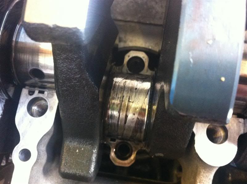
As you can see here, the big end shell isn't in great shape and the rod cap appears to be scored

Hopefully the rod will be able to be salvaged, but that can't be ascertained until it it cleaned up and measured.
I'm very suprised that with the big end fault I have found that there was no excess noise/vibration while the engine was idling.
SausageArm - 24/4/12 at 08:11 PM
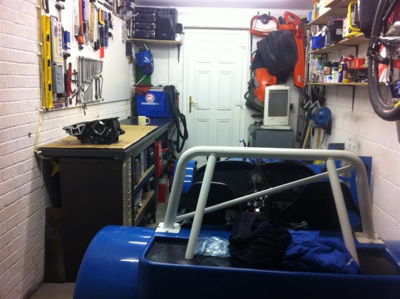
I gave the garage a tidy up to make some decent workspace to progress the engine overhaul
Removed the cam chain tensioner
Cam chain tensioner

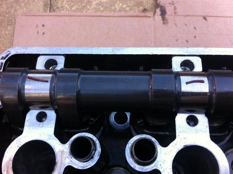
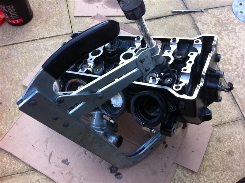
Cam cover removed, exposing the cams
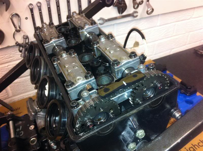

Camshaft retainer caps, camshafts and followers.

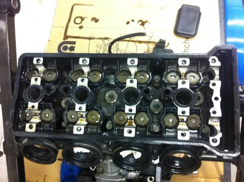
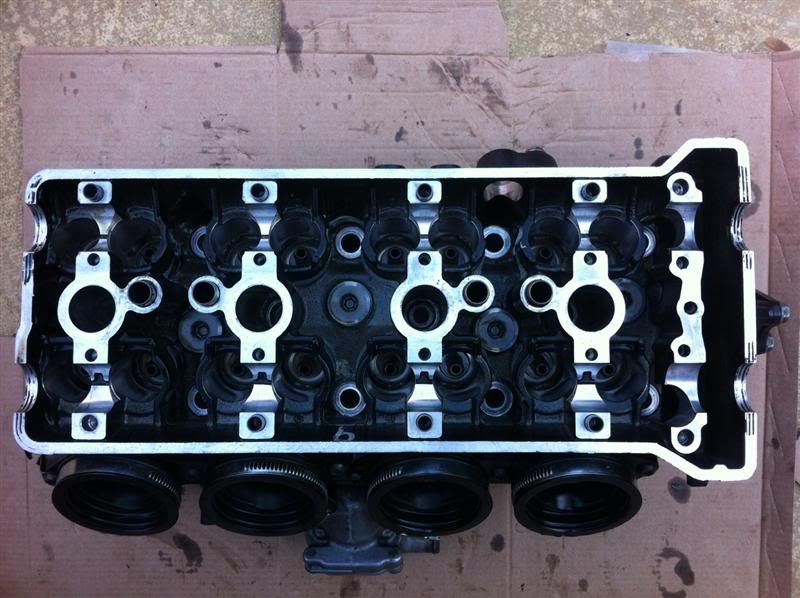
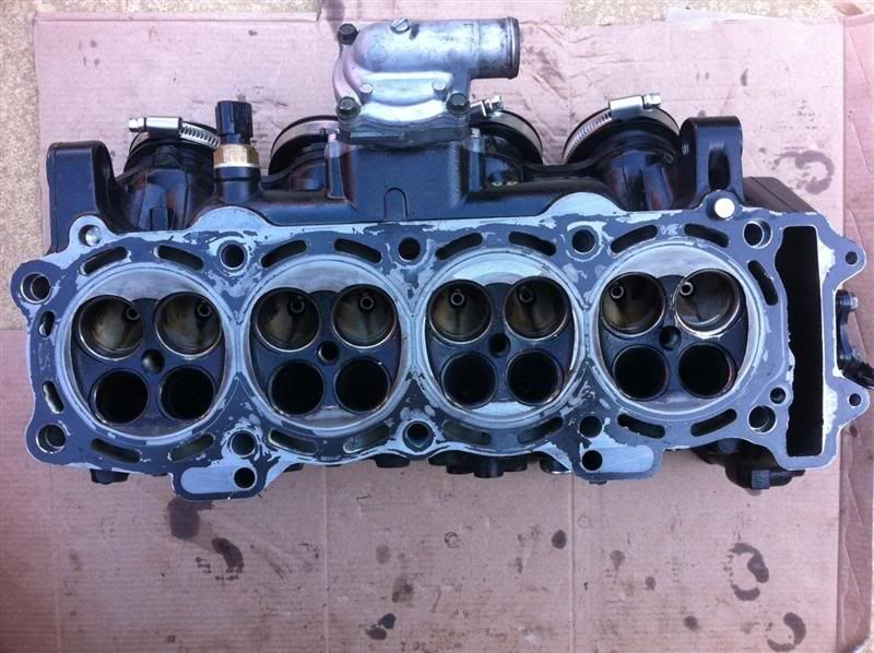
Cylinder head without camshafts and followers.
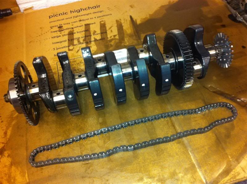
With the camshafts removed the crank was then pulled out the bottom of the engine.
Crankshaft and cam chain.
SausageArm - 24/4/12 at 08:13 PM
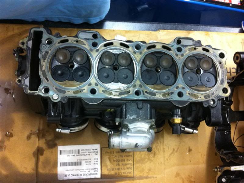
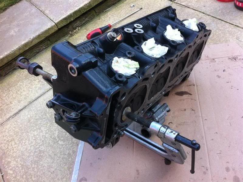
Pulled the head off, here it is sitting on the bench
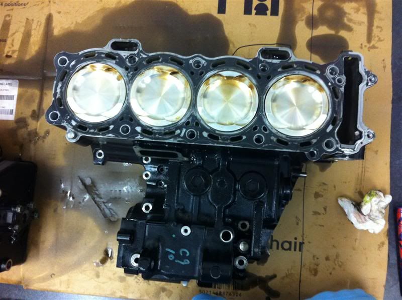
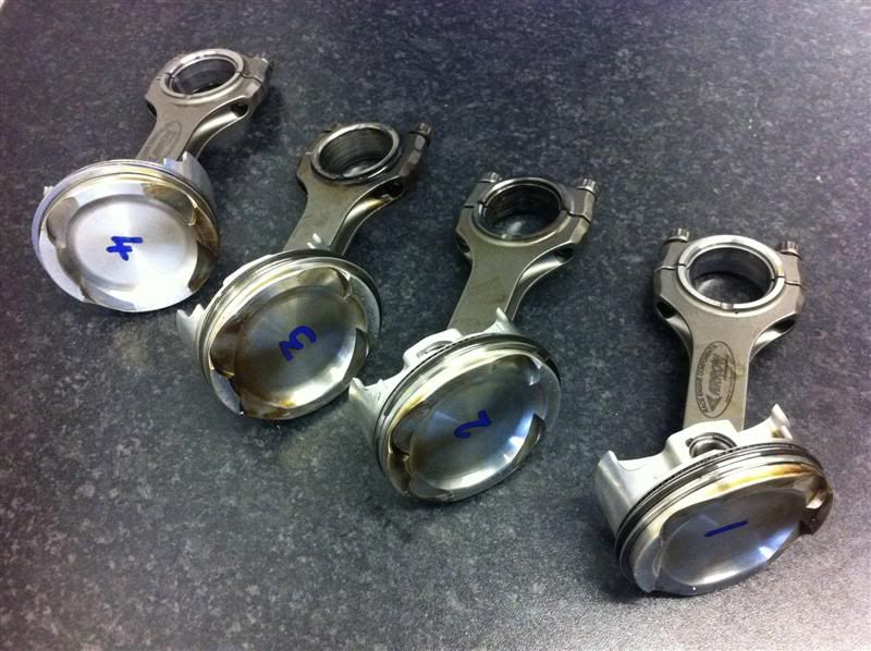
Bottom end and the shiney JE pistons
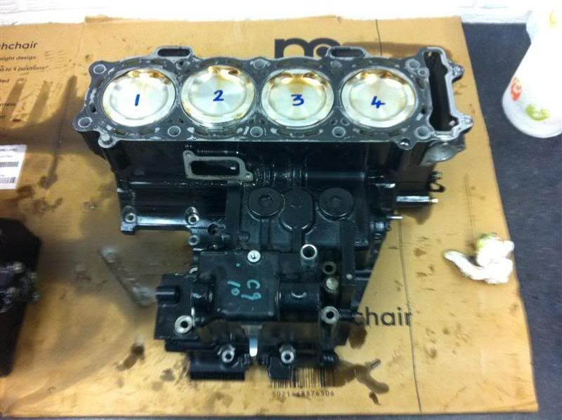
Numbered up so they go back in the correct positions
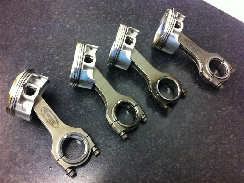
Arrow con rods and JE pistons laid out on the bench
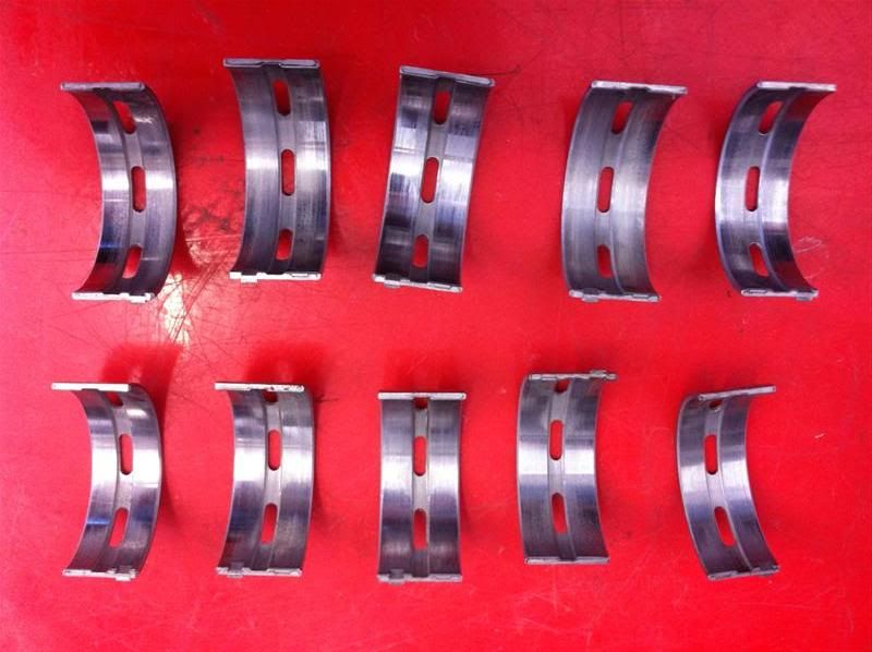
The crankshaft main bearings showing slight signs of wear
SausageArm - 24/4/12 at 08:18 PM
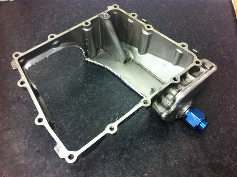
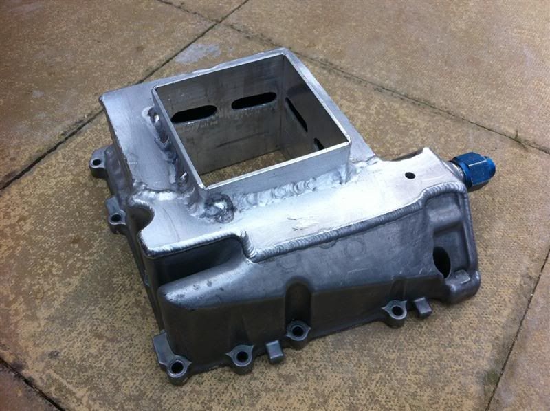
I butchered the standard sump, with the aim of giving it more capacity and also some baffles to stop the oil from moving around during
braking/acceleration/cornering. Will also be a good chance to practice and improve my TIG welding.
Here it is, in the early stages of modification
With aluminium plates welded to the sump to make it square shaped it should hold substantially more oil. 
I began making cardboard templates to transfer onto the 3mm aluminium plate I bought yesterday.
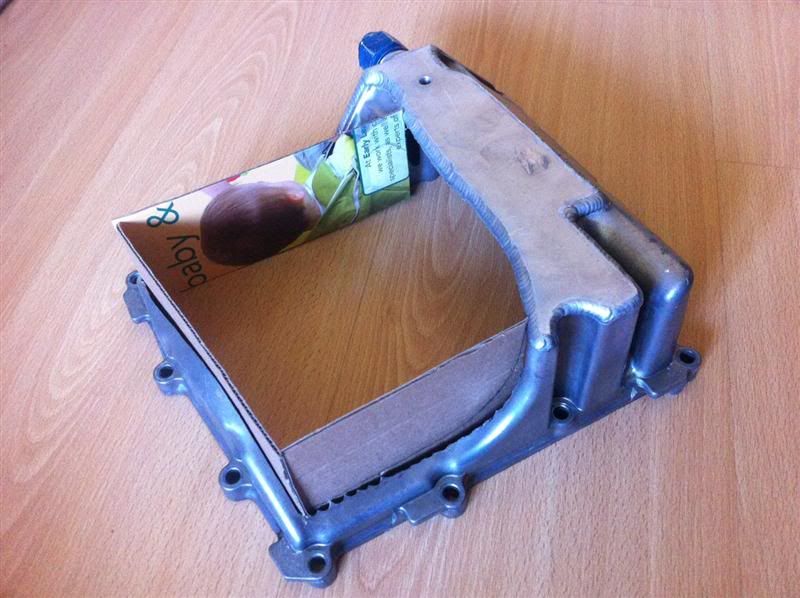
The templates for the sump sides look like this

When rested in position the sump looks like it holds a lot more oil than the standard one
one aluminium plate tacked in place
http://img.photobucket.com/albums/0903/Red16/Mac%20Worx%20RR%20Build/SumpModification13Medium.jpg
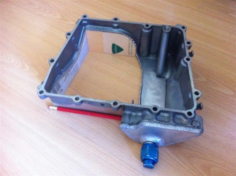
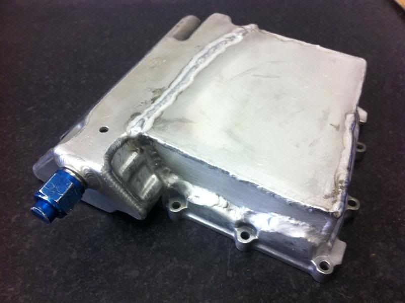
a bit of progress on the sump, it's now looking like this
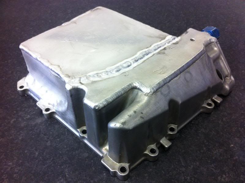
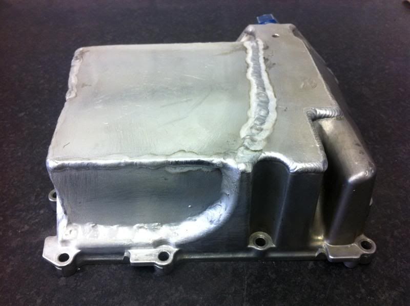
It's all water tight, as i found when i filled it to see what volume of water it held, it now holds 2.8 litres, which is definitely more than the
standard sump, unfortunately i didnt fill the standard sump before cutting it up, would've been nice to know the difference! Doh!
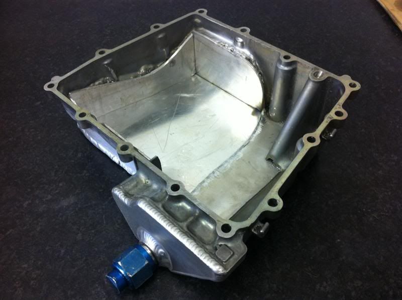
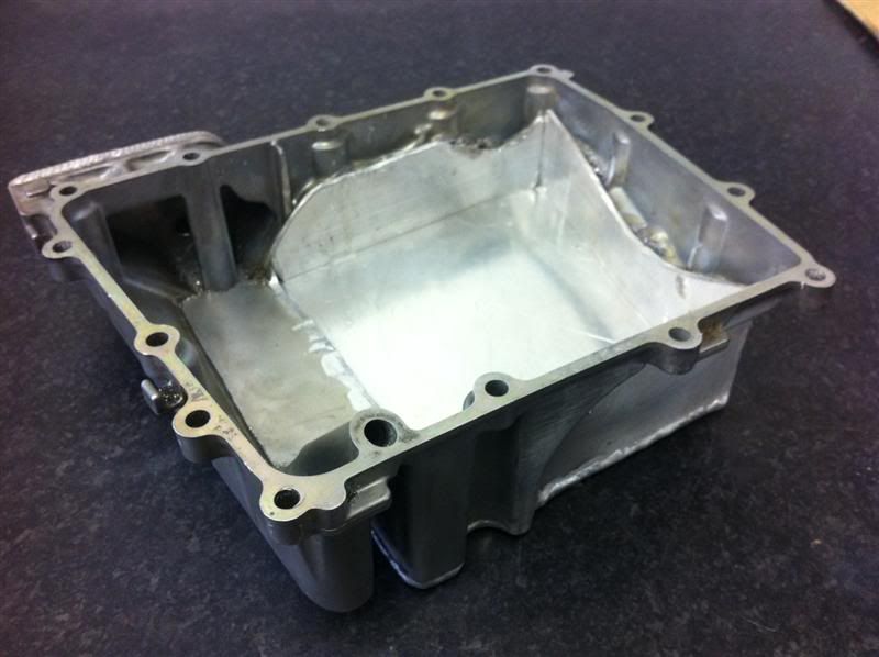
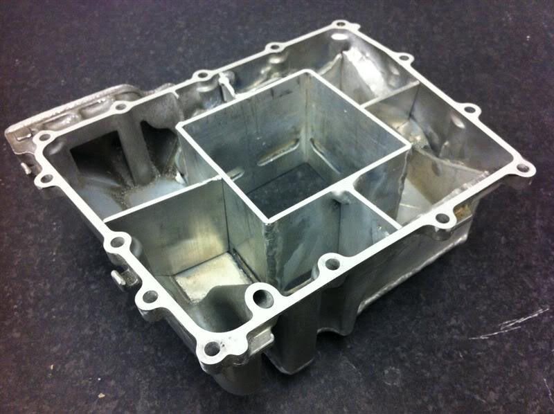
Here's the internal view, it's not baffled yet, as I'm still waiting on an oil pickup being delivered, once I have that in my
possession I can make the baffles accordingly.
SausageArm - 24/4/12 at 08:21 PM
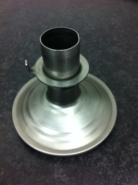
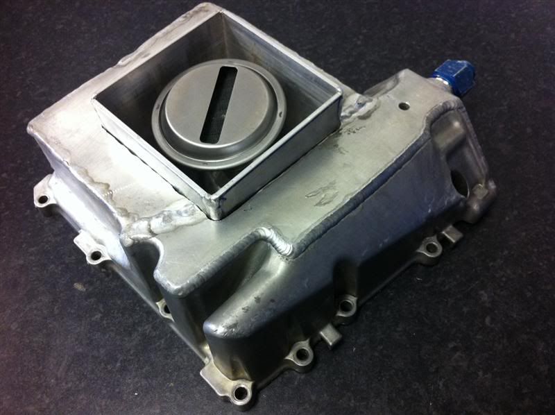
Here's the new oil pickup, it's meant for a CBR900RR Fireblade, but it's the perfect size and shape to be modified and used in my
sump.
Here it is
SausageArm - 24/4/12 at 08:23 PM
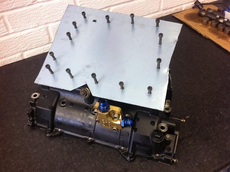
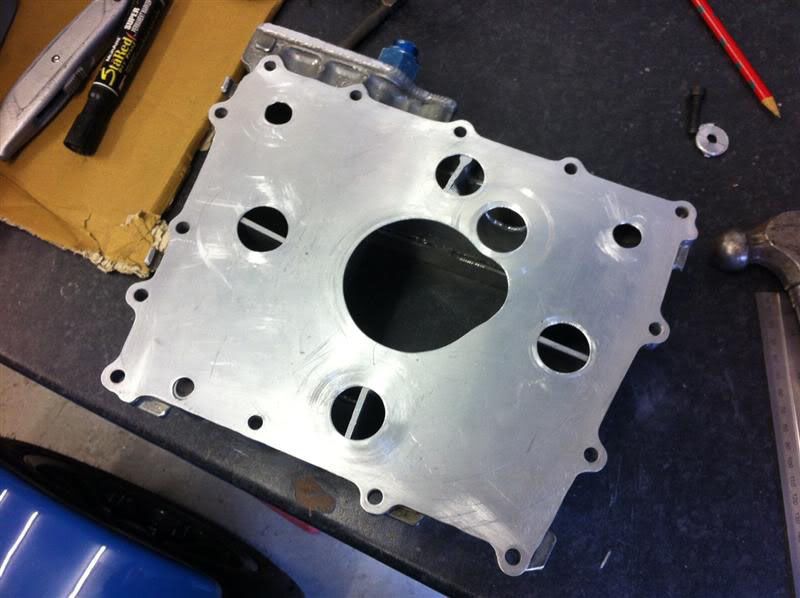
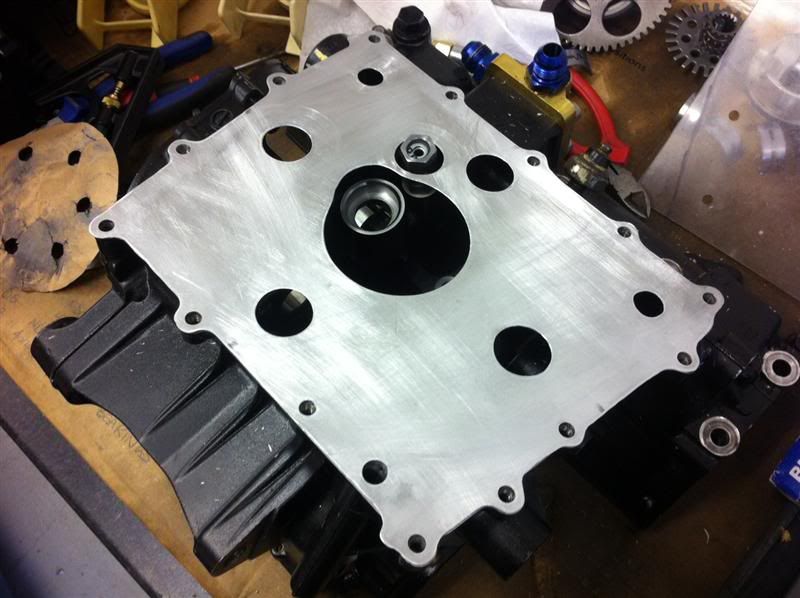
Next task was to sort out a baffle plate to go between the engine and sump, I marked out and drilled the holes for the oil return and sump mounting
bolts.
Here it is trial fitted to the engine to check hole spacings
It was then trimmed down to the shape of the engine/sump
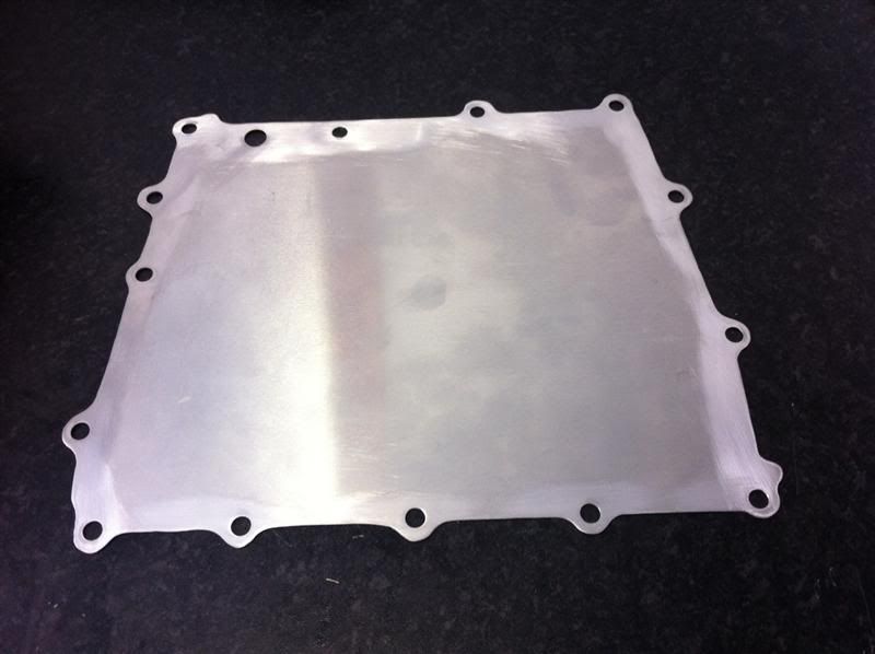
With it resting on the engine it looks like this
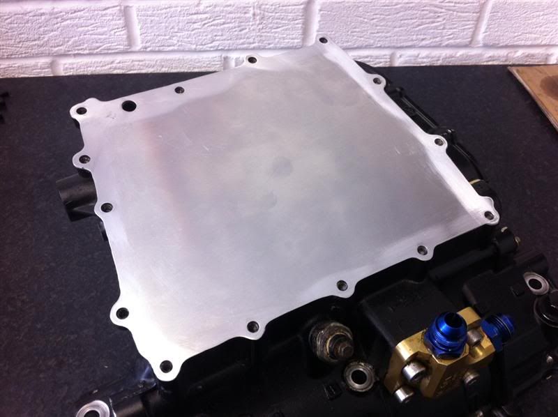
Once the sump baffles and oil pickup are finished I will add the necessary holes in the baffle plate to suit.
SausageArm - 24/4/12 at 08:45 PM
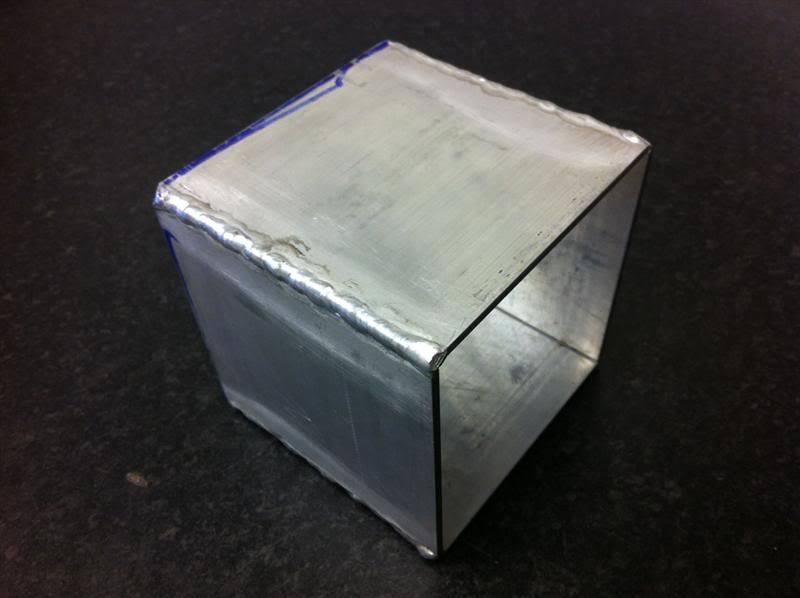
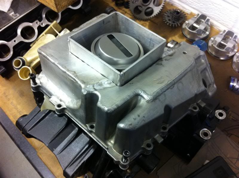
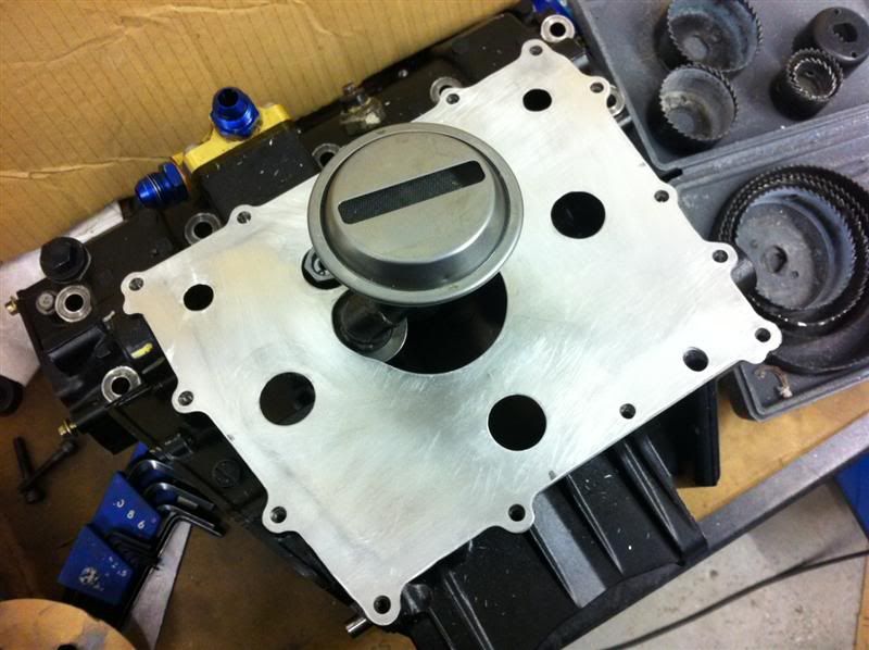
One baffle box for the centre of the sump.
The sump was then cut to allow the baffe box to be fitted.
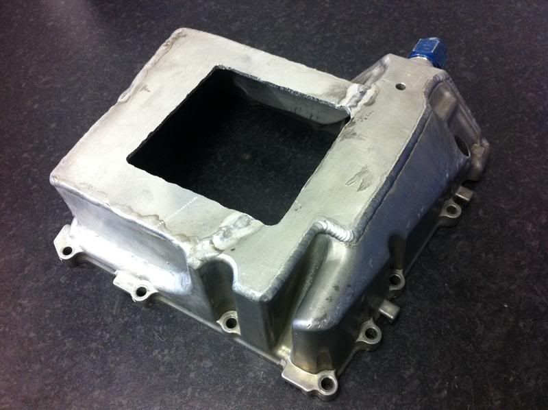
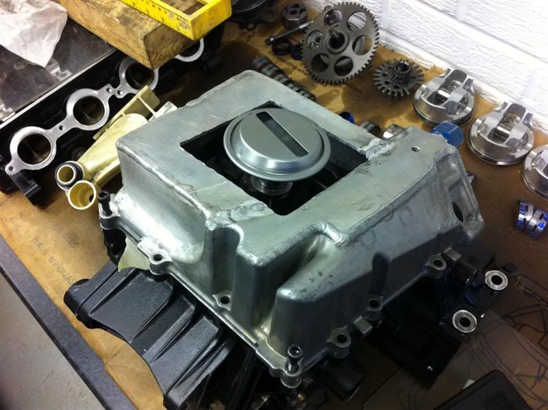
Here is roughly how it will look when assembled, although there will be extra baffle plates between the sump walls and the baffle box.
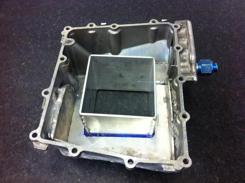
Once the pipework ha been fabricated, the Fireblade oil pickup will sit in the base of the sump something like this.
SausageArm - 24/4/12 at 08:48 PM
I'm waiting on some tube being delivered to allow the sump to be progressed, so I decided to leave that and move onto the cylinder head.
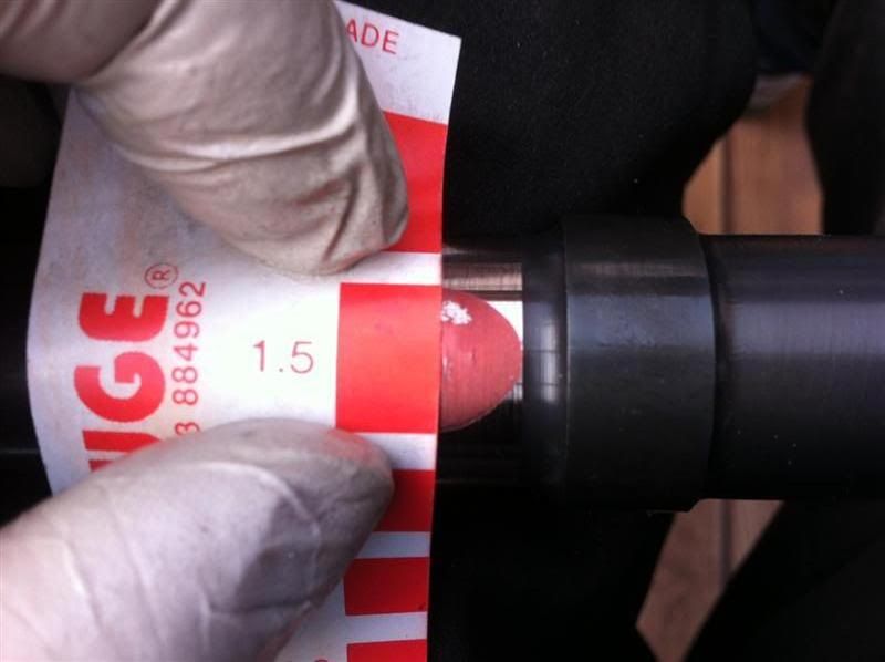
Before stripping the head I wanted to double check the cam journal to cap clearances, so strips of plastigauge were laid across the journals
All the cam caps were fitted, bolts torqued up and then removed, this crushed the plastigauge material, the clearances measured between 0.0015"
and 0.002", whcih were within manufacturers recommendation of 0.0015" and 0.0032"
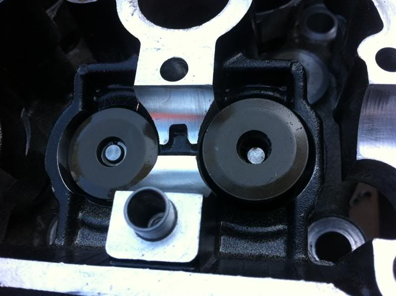
Next up was the task of removing the valves, a spring compressor was used to compress and hold the valve springs
Here you can see the valve spring has been compressed and the securing collets are accessable
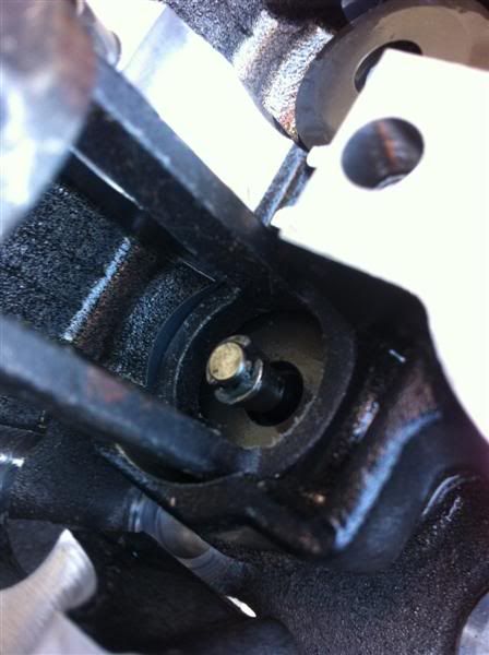
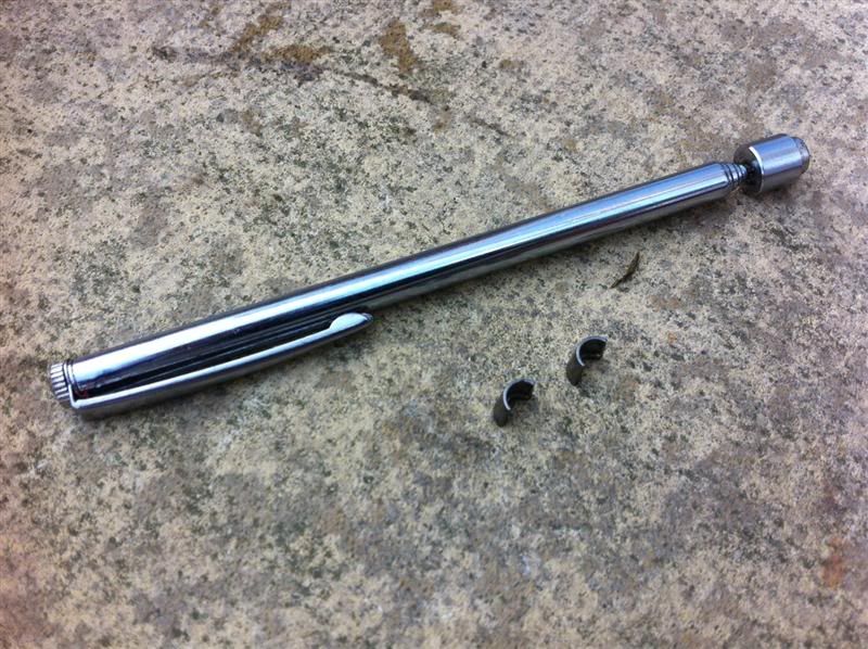
Using a telescopic magnet the collets were removed
With the valve spring compressor removed things look like this
The valve spring retainer was then removed
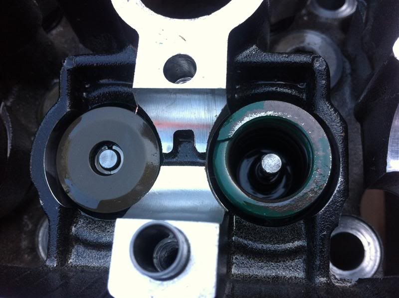
With the valve spring removed, you can see thevalve stem and valve stem oil seal
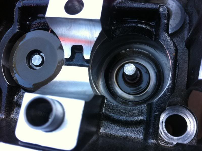
The valve them simply pushes out of the head.
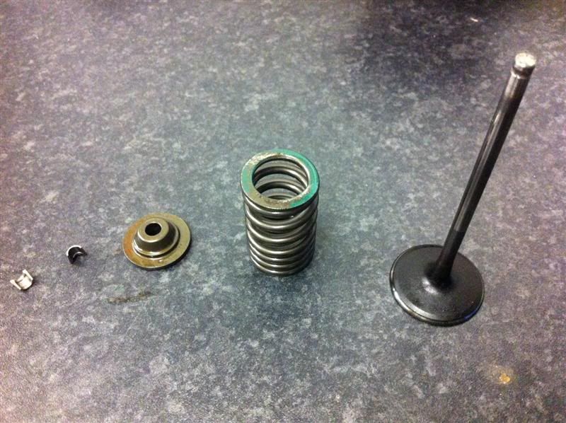
The bare cylinder head
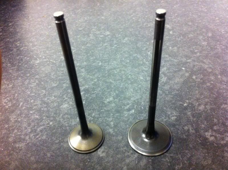
I cleaned all the deposits from the valves, here are a couple of before and after comparison photos
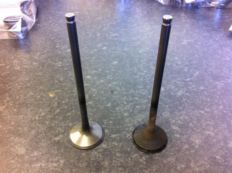
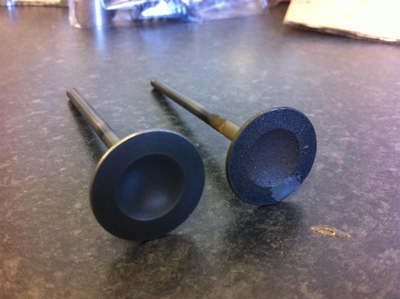
The valves stems were then measured, checked for damage/bending and llapped in with fine valve grinding paste
SausageArm - 24/4/12 at 08:50 PM
I've had an update from APE Raceparts, my Carrillo rods and gaskets are in stock and have been sent out to me today.
AJ Suttons sent out my new oil pump, filter, and other parts, they arrived today.
I spoke to Chris Applebee the other day regarding my crankshaft being reground, unfortunately when he checked it over, the big end journal number 3
was worn but still within the limits of a regrind and new shells, however the crankshaft was bent around this area, so it is officially scrap!
I have a spot of good news though, I took delivery of this 2005 engine yesterday
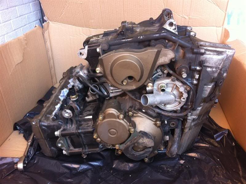
I spent this afternoon stripping it down to remove the crankshaft, the crankshaft has been measured up and bearing clearances checked with the old
bearings fitted in my turbo engine, everything looks good.
That means tomorrows jobs list consists of assembling the cylinder head, checking valve clearances and ordering up some new main and big end shells
and possibly some cam follower shims.
SausageArm - 24/4/12 at 08:57 PM
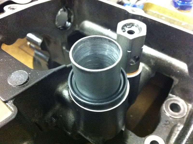
The tubing I bought from ebay earlier in the week, arrived today so I was able to make some progress on the oil pickup.
The inside diameter of the standard oil pickup seal is larger than the required pipework for the oil pickup. A larger piece of tube was used as a
sleeve and the tube for the oil pickup now slots inside this.
Here's the modified Fireblade oil pickup tacked together
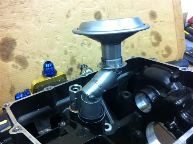
Here it is with the sump rested in position
Baffle rested roughly in position
The depth of the sump in the centre is still to be finalised, as is the oil pickup height, this is achievable because the sleeve is not welded to the
pipework so the height is still able to be altered easily.
beaver34 - 24/4/12 at 09:05 PM
Great work as normal!
Follow it on passion ford
T66 - 24/4/12 at 09:14 PM
Does Chris Applebee do stripped spark plug inserts ? and is he local to you ?
By the way top notch job, the alloy work is spot on.
SausageArm - 24/4/12 at 09:15 PM
quote:
Originally posted by beaver34
Great work as normal!
Follow it on passion ford
Thanks 
I'm stuck in a hotel room so thought I'd transfer the stuff from pf to here, someone else might be interesting in having a look at the
photos etc.
SausageArm - 24/4/12 at 09:19 PM
quote:
Originally posted by T66
Does Chris Applebee do stripped spark plug inserts ? and is he local to you ?
Nah Chris is down in Essex, I'm in South Shields, but I just posted the parts down and he sent them back up via courier.
There must be someone local who'd rework the plug insert for you.
Are you from the Morpeth area?
quote:
Originally posted by T66
By the way top notch job, the alloy work is spot on.
Thanks a lot it's not perfect but i think it's slowly improving.
mark chandler - 24/4/12 at 10:31 PM
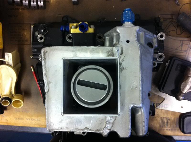
What's the point in dropping the pickup within that extend square box, you have just reduced the big sump to a tiny one.
If the box was flush inside the sump it creates a well, boxing around the sides like that you are just creating a little oil chamber, or are you then
going to drill holes around the base to let it fill up?
On the plus side, it�s easy to see how far behind car engines are when you crack open a bike, the engineering is superb!
SausageArm - 24/4/12 at 10:39 PM
Here's your answer Mark, I was just holding back the photos so as not to dump them all on here in one night.
And yes, bike engines are superbly engineered, I love the way everything is so small, light and compact.
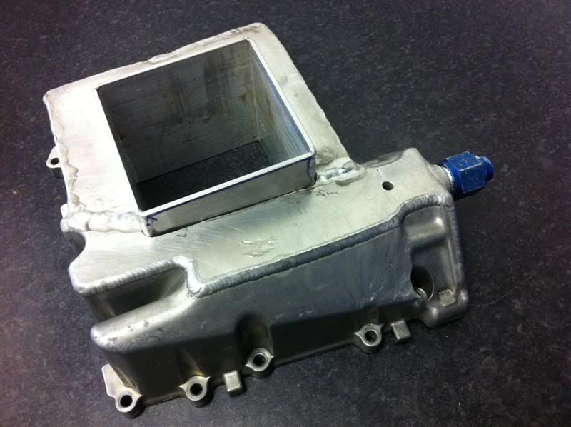
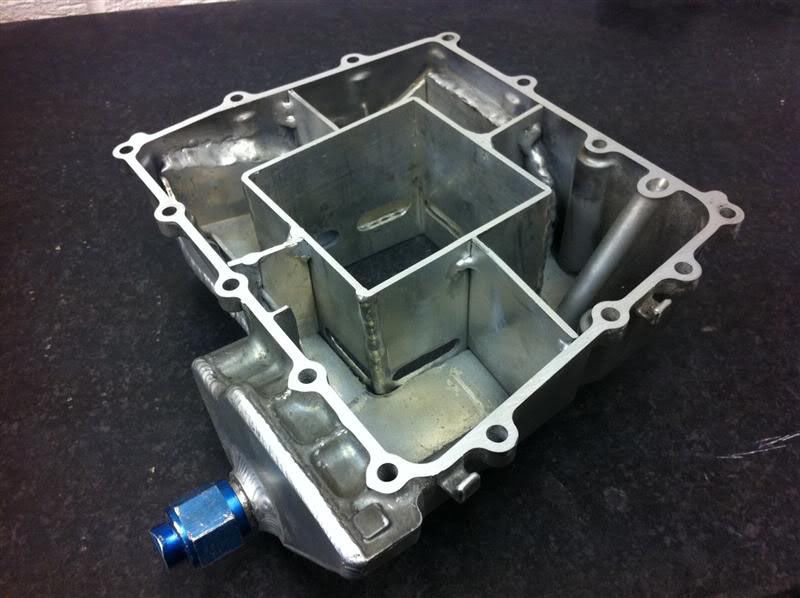
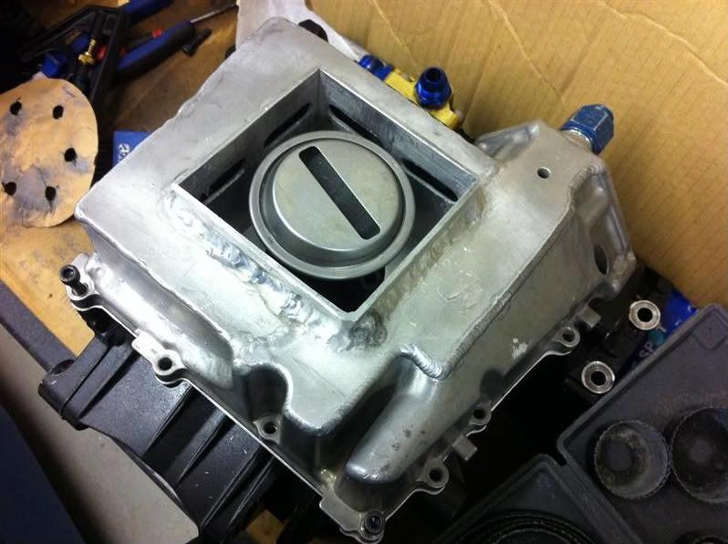
I cut the holes in the baffle box and mounted it in the sump
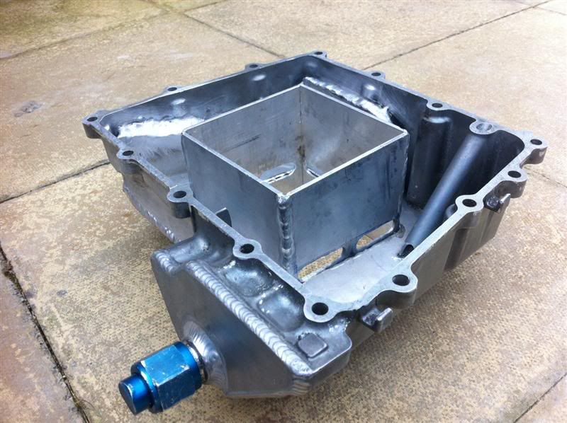
it was then welded into position
Here you can see the last of the sump baffle plates tack welded in position
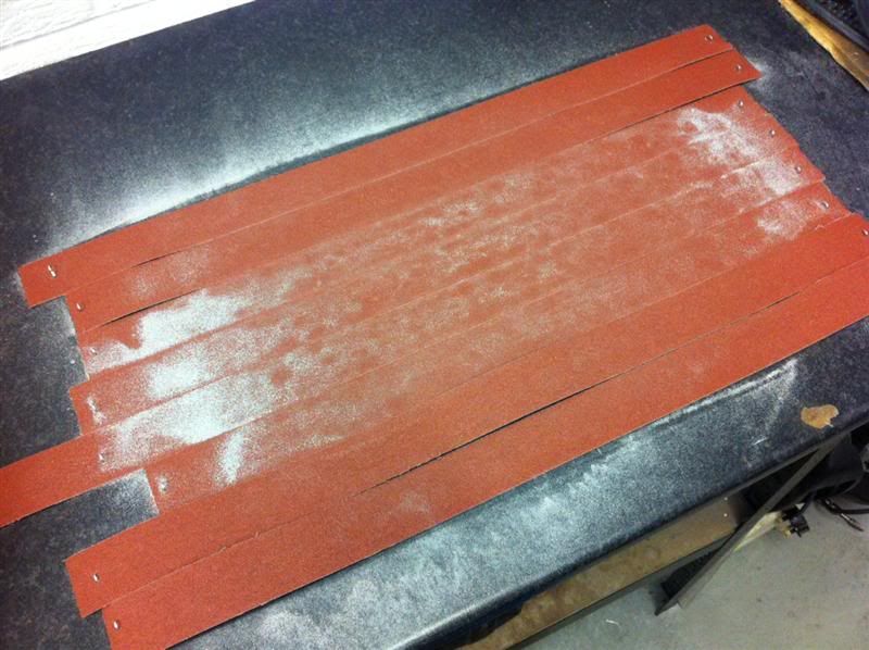
When i rested the sump on the engine casing for trial fitting it had warped slightly, so a few lengths of emery cloth were stapled to the work bench
and the flange face was lapped back to flat.
[Edited on 24/4/12 by SausageArm]
SausageArm - 24/4/12 at 10:41 PM
One set of H beam Carrillo con rods
In the con rod kit comes a bolt torque spec sheet, lubrication for the bolt threads and shoulders and some plastigauge for checking the bearing
clearances.
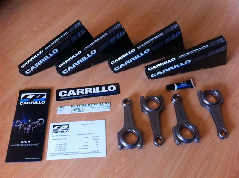
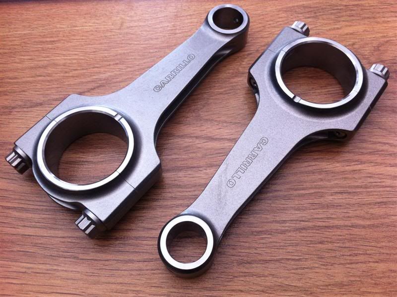
They were expensive but they look bloody fantastic and super strong! 
And just for the hell of it, here's a close up photo of two of the rods
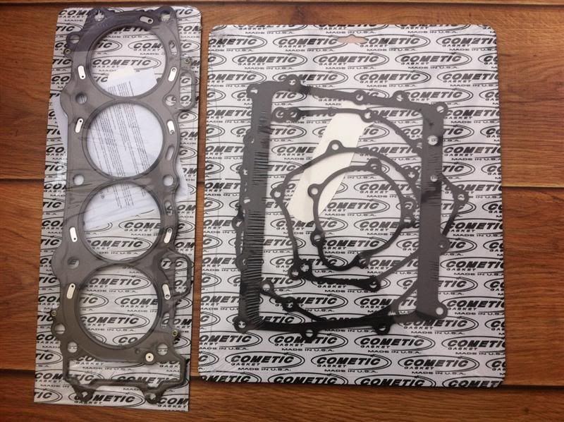
A Cometic multi layer steel head gasket and bottom end gasket set
FASTdan - 25/4/12 at 07:15 AM
Nice work :-) I was going to ask if your sump warped much. My Duratec one did - but unlike yours the Duratec has some horizontal fasteners too,
meaning that any skimming/lapping will cause location issues with these.
Did you have it bolted down when welding?
Proby - 25/4/12 at 07:27 AM
Excellent work Mr Sausage, looks fab, great pictures!
lotusmadandy - 25/4/12 at 08:43 AM
Nice work there Ben, i hope to see you back on the road soon
Im fitting the turbo on my zetec this week,so a run out up to steves
is on the cards.
Andy
Toprivetguns - 25/4/12 at 09:19 AM
My hat goes off to you sir ! Love the clinical approach to your workshop, especially the cardboard on bench surfaces.
I will follow this thread very closely.
coozer - 25/4/12 at 09:32 AM
Grrrrrr......
imp paul - 25/4/12 at 09:27 PM
love this thread top work ben its nice to see it all in picys hope it all works out for you
SausageArm - 26/4/12 at 08:00 PM
quote:
Originally posted by FASTdan
Nice work :-) I was going to ask if your sump warped much. My Duratec one did - but unlike yours the Duratec has some horizontal fasteners too,
meaning that any skimming/lapping will cause location issues with these.
Did you have it bolted down when welding?
Bit of a schoolboy error on my part there, I had it fastened down at first, then moved it to weld another section, got carried away and done the rest
without it fastened down, luckily it's ok now.
quote:
Originally posted by Proby
Excellent work Mr Sausage, looks fab, great pictures!
Thanks a lot.
quote:
Originally posted by lotusmadandy
Nice work there Ben, i hope to see you back on the road soon
Im fitting the turbo on my zetec this week,so a run out up to steves
is on the cards.
Great news Andy, don't forget to pop past mine sometime with the MK, be good to have a look/ride again. 
quote:
Originally posted by coozer
Grrrrrr......
What you grrrr'ing about Stevey?
quote:
Originally posted by imp paul
love this thread top work ben its nice to see it all in picys hope it all works out for you
Cheers Paul, I hope it does too, it should do really.
SausageArm - 26/4/12 at 08:01 PM
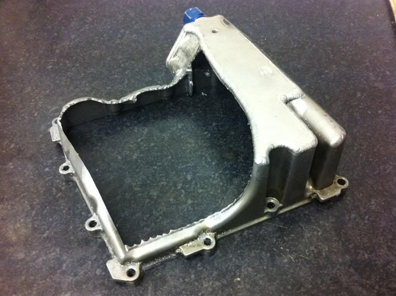
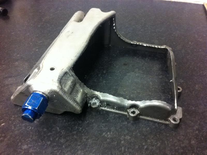
The baffle plate is now finished here she is resting on the sump
and on the engine casing
With the oil pickup in position
Trial assembly
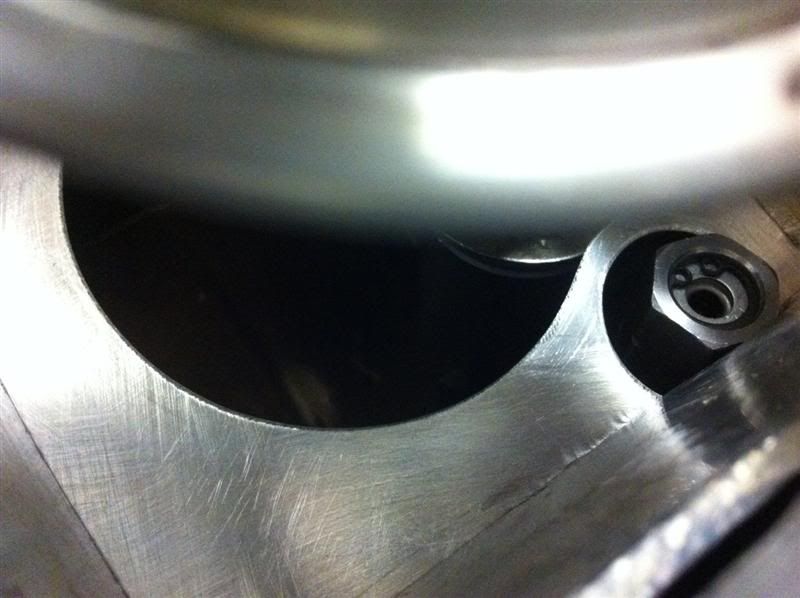
Looking into the centre of the sump, you can see the oil pickup at the top, baffle plate at the bottom and oil pressure relief valve to the right
SausageArm - 26/4/12 at 08:05 PM
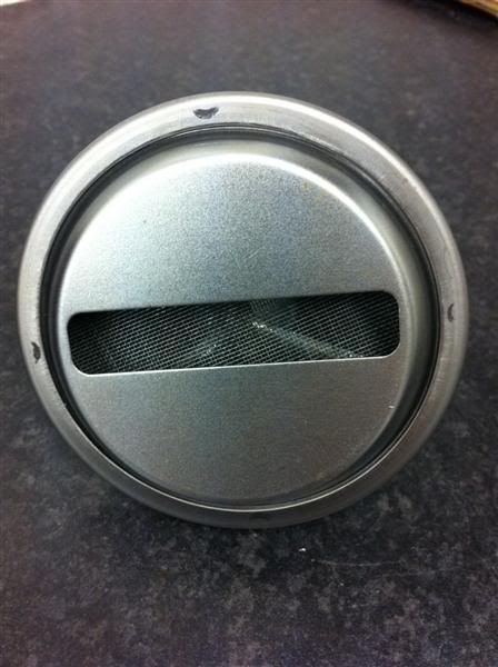
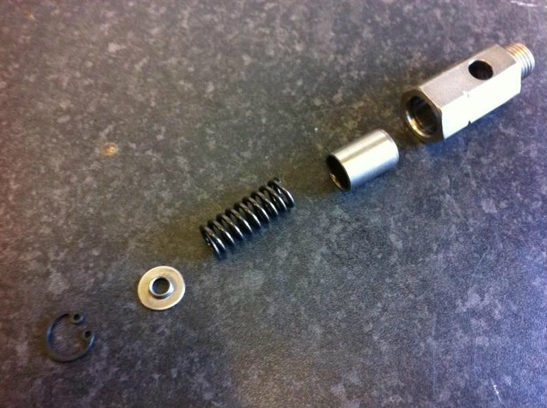
Here's the oil pressure relief valve stripped down.
From left to right... circlip, spring retainer, spring, piston, housing
While it was stripped down i cleaned it up and rebuilt it, connected it to a compressor and tested it via an adjustable pressure regulator, it began
leaking air immediately as the pressure was increased from 0psi and gradually leaked more and more until it held 70psi.
The relief valve was then stripped down again, fine valve grinding paste was applied to the piston which was then lapped in the housing, stripped and
cleaned thoroughly. When retested it held pressure up to around 20psi then began to leak until it maintained 70psi of pressure. Much better than the
first test.
The valve was stripped again and rebuilt with a standard M6 washer fitted between the circlip and the spring retainer, the thickness of the washer was
measured at 1.55mm, this washer acts as a shim and increases the preload of the spring, thereby increasing the oil pressure setting of the relief
valve. This time when tested it held pressure up to around 25-30psi then began to leak until it maintained 90psi of pressure.
This additional oil pressure should help to reduce the chance of bearing failure from low oil pressure at high RPM and make up for any pressure drops
through my external oil lines and oil cooler. I'll be fitting an oil pressure guage too, so I can keep an eye on things.
SausageArm - 26/4/12 at 08:11 PM
Checking the valve clearances.
The recommended Kawasaki clearances are,
Exhaust 0.17mm - 0.22mm (0.0067" - 0.0087"
Inlet 0.15mm - 0.24mm (0.0059" - 0.0094"
Here are some photos showing how I done it...
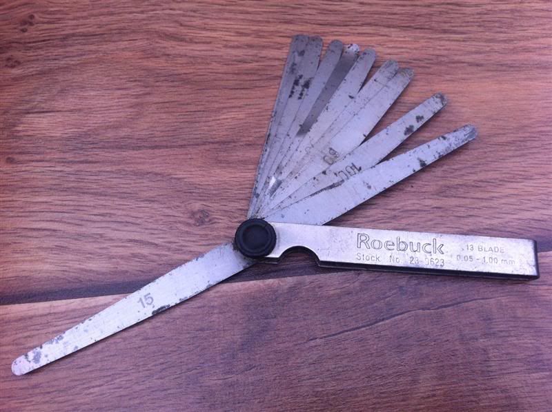
First off you'll need a set of feeler gauges, metric or imperial, it's entirely up to you
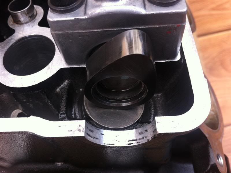
Set the cam lobe in this position for the clearance you wish to measure
Slide the feeler gauge blade between the cam lobe and the cam follower, making a note of the largest feeler gauge blade you can fit in the gap, this
is your valve clearance measurement.
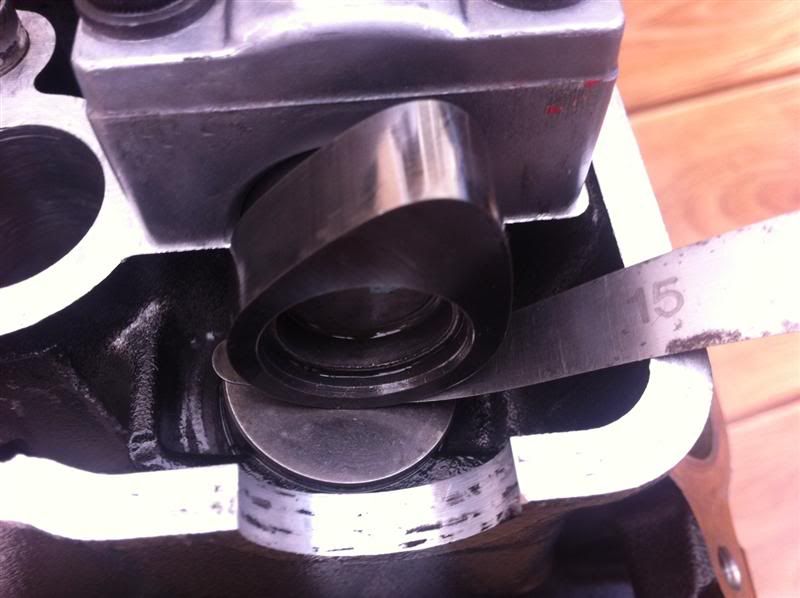
I measured the inlet clearances at 0.15-0.22mm and exhaust clearances at 0.18-22mm, they were all within tolerance, so no need to adjust them.
coozer - 26/4/12 at 08:42 PM
Grrr... cause I'm not as far up with the turbo build