SausageArm
|
| posted on 26/4/12 at 08:01 PM |

|
|
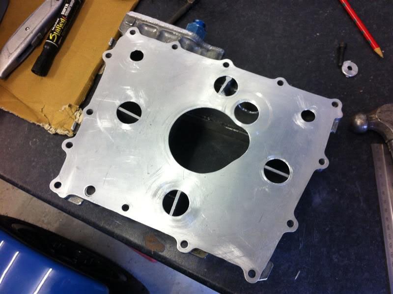
The baffle plate is now finished  here she is resting on the sump here she is resting on the sump
and on the engine casing
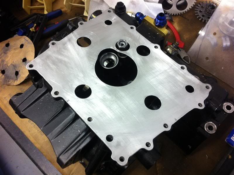
With the oil pickup in position
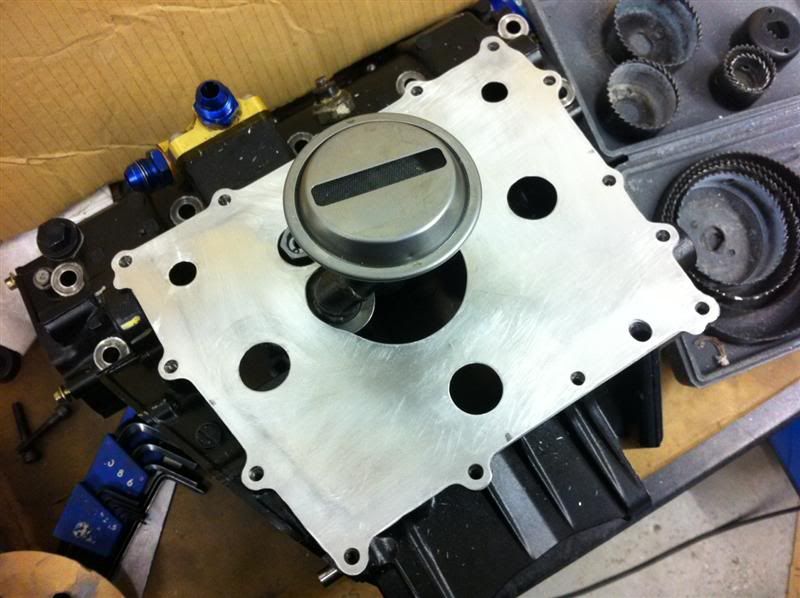
Trial assembly
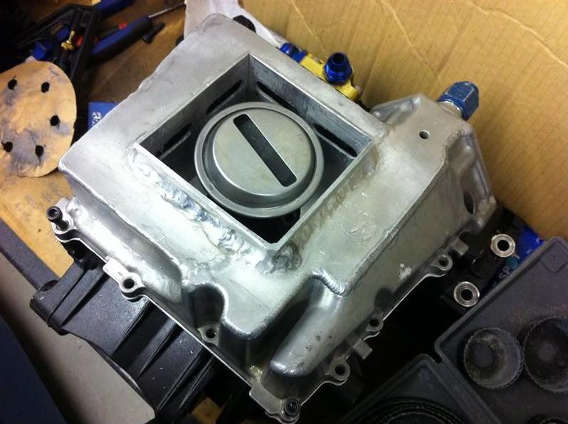
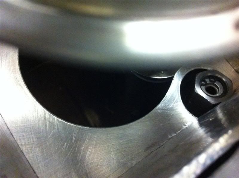
Looking into the centre of the sump, you can see the oil pickup at the top, baffle plate at the bottom and oil pressure relief valve to the right
|
|
|
|
|
SausageArm
|
| posted on 26/4/12 at 08:05 PM |
|
|
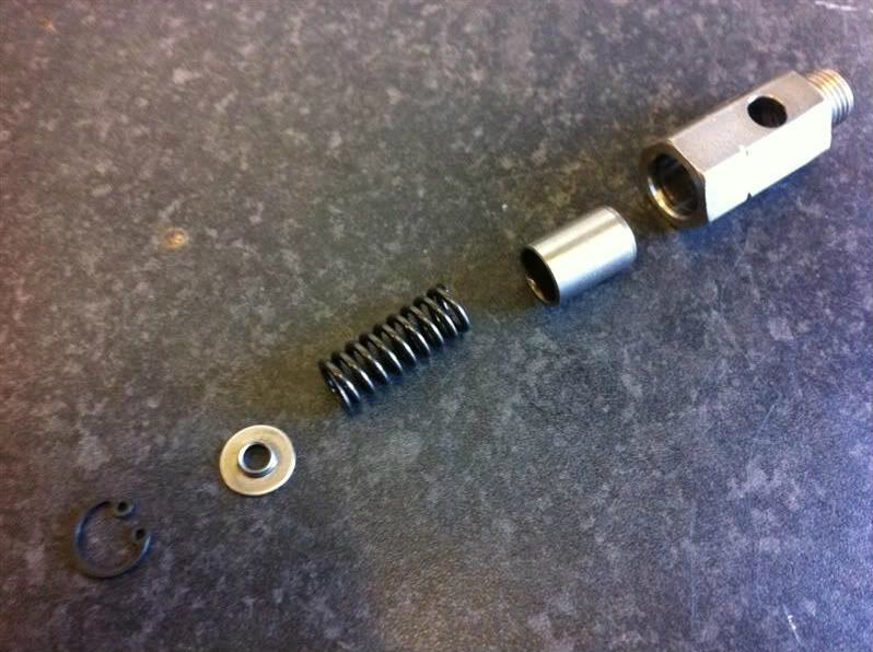
Here's the oil pressure relief valve stripped down.
From left to right... circlip, spring retainer, spring, piston, housing
While it was stripped down i cleaned it up and rebuilt it, connected it to a compressor and tested it via an adjustable pressure regulator, it began
leaking air immediately as the pressure was increased from 0psi and gradually leaked more and more until it held 70psi.
The relief valve was then stripped down again, fine valve grinding paste was applied to the piston which was then lapped in the housing, stripped and
cleaned thoroughly. When retested it held pressure up to around 20psi then began to leak until it maintained 70psi of pressure. Much better than the
first test.
The valve was stripped again and rebuilt with a standard M6 washer fitted between the circlip and the spring retainer, the thickness of the washer was
measured at 1.55mm, this washer acts as a shim and increases the preload of the spring, thereby increasing the oil pressure setting of the relief
valve. This time when tested it held pressure up to around 25-30psi then began to leak until it maintained 90psi of pressure.
This additional oil pressure should help to reduce the chance of bearing failure from low oil pressure at high RPM and make up for any pressure drops
through my external oil lines and oil cooler. I'll be fitting an oil pressure guage too, so I can keep an eye on things.
|
|
|
SausageArm
|
| posted on 26/4/12 at 08:11 PM |
|
|
Checking the valve clearances.
The recommended Kawasaki clearances are,
Exhaust 0.17mm - 0.22mm (0.0067" - 0.0087"
Inlet 0.15mm - 0.24mm (0.0059" - 0.0094"
Here are some photos showing how I done it...
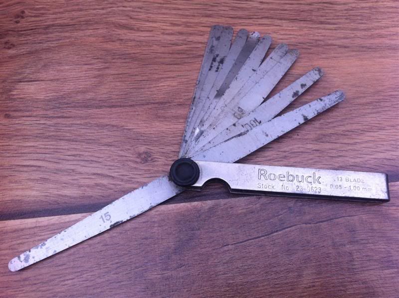
First off you'll need a set of feeler gauges, metric or imperial, it's entirely up to you
Set the cam lobe in this position for the clearance you wish to measure
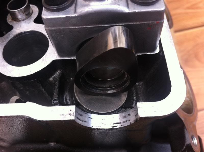
Slide the feeler gauge blade between the cam lobe and the cam follower, making a note of the largest feeler gauge blade you can fit in the gap, this
is your valve clearance measurement.
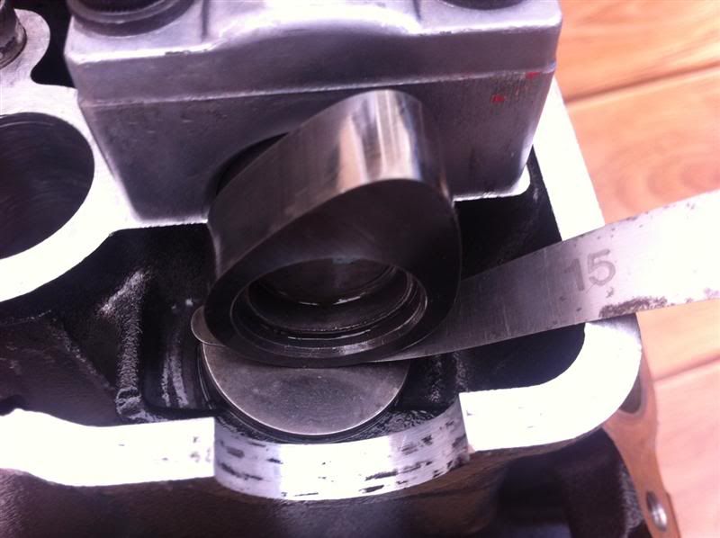
I measured the inlet clearances at 0.15-0.22mm and exhaust clearances at 0.18-22mm, they were all within tolerance, so no need to adjust them.
|
|
|
coozer
|
| posted on 26/4/12 at 08:42 PM |
|
|
Grrr... cause I'm not as far up with the turbo build 
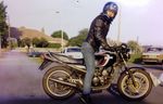
1972 V8 Jago
1980 Z750
|
|
|