Doug68
|
| posted on 12/8/07 at 02:50 PM |

|
|
I hope this comments will be helpful...
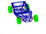
Blue lines delete.
Red Lines add. Verticals and horizontals 50x25 and bracing 25 square.
"A" I don't see where the load from this can go? you'll be sitting the other side so any sort of structure will be hard to do
there I'm guessing?
"B" Lower the whole frame and mount the suspension brackets on top to get rid of the dog leg?
"C" I suspect the control arm would clear a lowered frame section? So the bottom tube can be straightened out.
My other lesson for the day is don't make tube join angle too acute or they become a PITA to weld.
[Edited on 12/8/07 by Doug68]
Rescued attachment EDIT.jpg
Doug. 1TG
Sports Car Builders WA
|
|
|
|
|
kb58
|
| posted on 12/8/07 at 06:26 PM |
|
|
After you tentatively place the tubes, make sure there's still room for your tires! The foward lower tubes look like they're getting
close.
Mid-engine Locost - http://www.midlana.com
And the book - http://www.lulu.com/shop/kurt-bilinski/midlana/paperback/product-21330662.html
Kimini - a tube-frame, carbon shell, Honda Prelude VTEC mid-engine Mini: http://www.kimini.com
And its book -
http://www.lulu.com/shop/kurt-bilinski/kimini-how-to-design-and-build-a-mid-engine-sports-car-from-scratch/paperback/product-4858803.html
|
|
|
rpmagazine
|
| posted on 12/8/07 at 10:33 PM |
|
|
quote:
Originally posted by Doug68
I hope this comments will be helpful...
Blue lines delete.
Red Lines add. Verticals and horizontals 50x25 and bracing 25 square.
"A" I don't see where the load from this can go? you'll be sitting the other side so any sort of structure will be hard to do
there I'm guessing?
"B" Lower the whole frame and mount the suspension brackets on top to get rid of the dog leg?
"C" I suspect the control arm would clear a lowered frame section? So the bottom tube can be straightened out.
My other lesson for the day is don't make tube join angle too acute or they become a PITA to weld.
[Edited on 12/8/07 by Doug68]
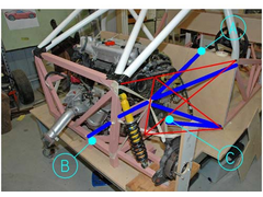
A attaches to a cross beam that is also the apex of a transverse box section made from Al honeycomb panel. This boz section houses the 75lt fuel tank
on the passengers side.
B, despite my great reservations I am considering a fabricated upright. I can construct the dogleg section (under the gearbox) such that there is
minimal loss of stiffness, but it adds weight and is less than elegant. The point B you note has a removable diagonal from the mid trinode, not shown
in this image...I'll try to find an image of it.
Not quite sure what you mean by C. The bottom tube is straight. The forward leading tape represents the forward leg of the L arm and the mount would
be just in front of the angled tube. There is another tube not shown at this point that mirrors the diagonal and runs to the center of the car.
Agreed re the welding, the mockup has already solved many of these issues. The rear structure will be a mix of round and square tube.
KB it is deceiving as there is approx 5" of clearance. The width of the block of wood represents the absolute maximum tyre I would consider
possible at 335 wide and that just clears. I am intending to use 255.40.17 at the rear.
[Edited on 12/8/07 by rpmagazine]
[Edited on 12/8/07 by rpmagazine]
[Edited on 12/8/07 by rpmagazine]
|
|
|
TheGecko
|
| posted on 13/8/07 at 03:54 AM |
|
|
Neil,
Good to see you making progress. Also good to see I'm not the only one mocking up in "structural masking tape" 
Dominic
 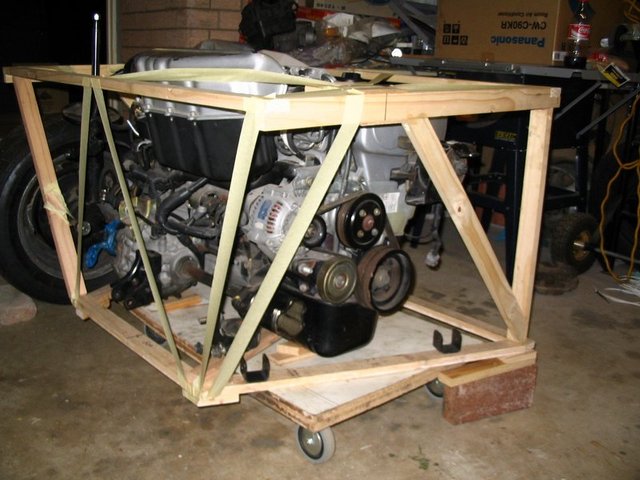
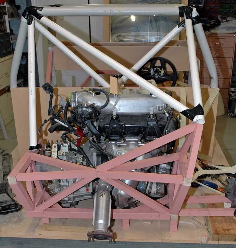
Mock up engine bay
|
|
|
rpmagazine
|
| posted on 13/8/07 at 04:10 AM |
|
|
Not at all...you gave me the idea. I did find a secondary benefit though: I made up the basic structure with flexible joints (hot glue and tape) and
ran tape lines where I thought tubes needed to go. Then I pushed on various nodes simulating loads/forces being fed into the chassis. I then watched
which tapes deflected/changed and this told me where the structure needed to go. It saved me a HUGE amount of time and work!
|
|
|
rpmagazine
|
| posted on 22/8/07 at 11:56 AM |
|
|
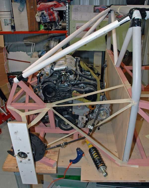
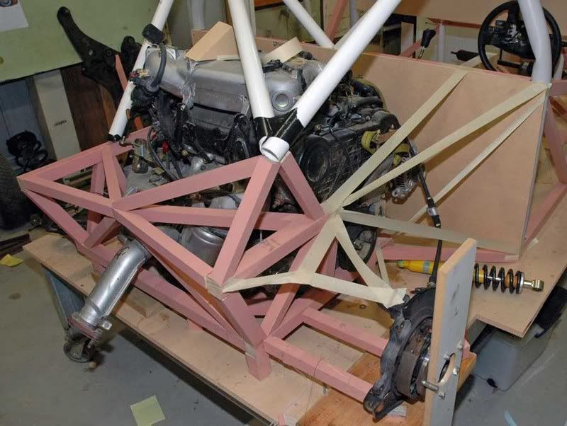
Rear structure update: The joy of non asymmetric tetrahedrons in a non planar truss -
|
|
|
Spyderman
|
| posted on 22/8/07 at 05:23 PM |
|
|
I am a little confused. If all of those tape lines are going to be structural tubes how are you going to get the engine in and out? 
Spyderman
|
|
|
rpmagazine
|
| posted on 22/8/07 at 10:20 PM |
|
|
Yes the tape lines represent structural tubes. There are about 5 options, but the two under serious consideration are having the majority of the rear
structure detach from the main hoop etc. The second is that the lowest/floor section will detach from the firewall and from immediately prior to the
first transverse arm, which means the complete drive train can drop out the bottom of the car...minus driveshafts.
[Edited on 22/8/07 by rpmagazine]
|
|
|