davidimurray
|
| posted on 31/12/14 at 07:10 PM |

|
|
Nippon Denso Alternator Charge Light
Completed the wiring mods for the Duratec and powered the car back up to check everything over. The good news is that the engine cranked over, built
up oil pressure and even had a spark
The bad news is that the charging light isn't working. Alternator is a little 45A Nippon Denso unit. With the ignition on, the charging light
does not illuminate. In terms of the wiring, because I have an LED in the dash so I've got a lamp in parallel under the dash which is the setup
I had working with the old Lucas alternator.
I've taken a wire off one side of the bulb to give 12V to the switched live and sense connections. The other side of the bulb is connected to
the alternator charge light and the LED. With the ignition on I would expect 0V on the ignition light wire, but what I get is 12V
Do these alternators give out 12V on the light wire when not running and 0V when they are running? I can't start the engine yet to check what is
going on.
Cheers
Dave
Gallery 1 http://www.facebook.com/media/set/?set=a.116893465324.130778.601005324
Gallery 2 http://www.facebook.com/media/set/?set=a.245243755324.181913.601005324&l=a9831a9319
Gallery 3 http://www.facebook.com/media/set/?set=a.440671625324.232627.601005324&l=3f0d42c523
Gallery 4 http://www.facebook.com/media/set/?set=a.490098255324.297598.601005324&l=efb083b7df
Gallery 5 http://www.facebook.com/media/set/?set=a.10150244028550325.366987.601005324&l=583fd5cd3a
Gallery 6 http://www.facebook.com/media/set/?set=a.10150550640070325.430417.601005324&type=3&l=fe779b358c
Duratec Engine Swap https://www.facebook.com/media/set/?set=a.10152527759580325.1073741828.601005324&type=1&l=40aae5e72f " target="_blank"> https://www.facebook.com/media/set/?set=a.10152527759580325.1073741828.601005324&type=1&l=40aae5e72f
|
|
|
|
|
blakep82
|
| posted on 31/12/14 at 07:20 PM |
|
|
Don't forget leds are diodes and block current in a particular direction, try switching the connections round first, as whatever way it works,
when you switch the ignition on, current flows in 1 particular direction to illuminate a normal bulb.
Chances are your led is blocking the current
________________________
IVA manual link http://www.businesslink.gov.uk/bdotg/action/detail?type=RESOURCES&itemId=1081997083
don't write OT on a new thread title, you're creating the topic, everything you write is very much ON topic!
|
|
|
daviep
|
| posted on 31/12/14 at 07:28 PM |
|
|
I think a drawing of your wiring may help you get a more accurate answer.
The warning lamp should supply 12v to the alternator which provides an earth, when the alternator starts charging the lamp terminal changes up to 12v
so that the lamp goes out.
To test the lamp circuit disconnect the lamp wire from the alternator and touch it against a good earth, the bulb should light. If it doesn't
the fault lies within the lamp circuit not the alternator. If it does light then there is a problem with the alternator or the alternator isn't
earthed.
Regards
Davie
A truly great library contains something in it to offend everyone.
|
|
|
davidimurray
|
| posted on 31/12/14 at 07:52 PM |
|
|
quote:
Originally posted by daviep
I think a drawing of your wiring may help you get a more accurate answer.
The warning lamp should supply 12v to the alternator which provides an earth, when the alternator starts charging the lamp terminal changes up to 12v
so that the lamp goes out.
To test the lamp circuit disconnect the lamp wire from the alternator and touch it against a good earth, the bulb should light. If it doesn't
the fault lies within the lamp circuit not the alternator. If it does light then there is a problem with the alternator or the alternator isn't
earthed.
Regards
Davie
Will get the circuits drawn up, but if I disconnect the ign light wire and ground them then the lamp and LED illuminates as it should.
It seems that the alternator is giving out 12V when not running rather than the 0V I expected like most alternators
I've checked continuity for earth from the alternator back to the chassis and it was ok.
[Edited on 31/12/14 by davidimurray]
[Edited on 31/12/14 by davidimurray]
Gallery 1 http://www.facebook.com/media/set/?set=a.116893465324.130778.601005324
Gallery 2 http://www.facebook.com/media/set/?set=a.245243755324.181913.601005324&l=a9831a9319
Gallery 3 http://www.facebook.com/media/set/?set=a.440671625324.232627.601005324&l=3f0d42c523
Gallery 4 http://www.facebook.com/media/set/?set=a.490098255324.297598.601005324&l=efb083b7df
Gallery 5 http://www.facebook.com/media/set/?set=a.10150244028550325.366987.601005324&l=583fd5cd3a
Gallery 6 http://www.facebook.com/media/set/?set=a.10150550640070325.430417.601005324&type=3&l=fe779b358c
Duratec Engine Swap https://www.facebook.com/media/set/?set=a.10152527759580325.1073741828.601005324&type=1&l=40aae5e72f " target="_blank"> https://www.facebook.com/media/set/?set=a.10152527759580325.1073741828.601005324&type=1&l=40aae5e72f
|
|
|
davidimurray
|
| posted on 31/12/14 at 08:25 PM |
|
|
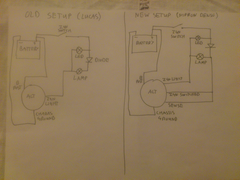
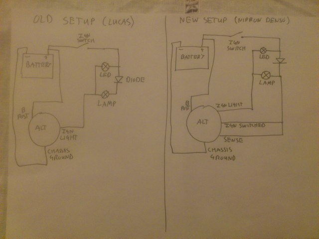
This is the old and new wiring setup. The only real difference is the addition of the switched and sense lines
Description
Gallery 1 http://www.facebook.com/media/set/?set=a.116893465324.130778.601005324
Gallery 2 http://www.facebook.com/media/set/?set=a.245243755324.181913.601005324&l=a9831a9319
Gallery 3 http://www.facebook.com/media/set/?set=a.440671625324.232627.601005324&l=3f0d42c523
Gallery 4 http://www.facebook.com/media/set/?set=a.490098255324.297598.601005324&l=efb083b7df
Gallery 5 http://www.facebook.com/media/set/?set=a.10150244028550325.366987.601005324&l=583fd5cd3a
Gallery 6 http://www.facebook.com/media/set/?set=a.10150550640070325.430417.601005324&type=3&l=fe779b358c
Duratec Engine Swap https://www.facebook.com/media/set/?set=a.10152527759580325.1073741828.601005324&type=1&l=40aae5e72f " target="_blank"> https://www.facebook.com/media/set/?set=a.10152527759580325.1073741828.601005324&type=1&l=40aae5e72f
|
|
|
daviep
|
| posted on 31/12/14 at 08:40 PM |
|
|
Couple of questions/obsevations
1: I would say your switched live and battery sense are connected to the wrong side of the lamp
2: What is the purpose of the diode
Regards
Davie
A truly great library contains something in it to offend everyone.
|
|
|
Chris_Xtreme
|
| posted on 31/12/14 at 08:41 PM |
|
|
can't say why,. but it seems wrong to me to have the sense wire joined up with the charge light.
|
|
|
r1_pete
|
| posted on 31/12/14 at 08:49 PM |
|
|
Useful info for ND wiring here
|
|
|
davidimurray
|
| posted on 31/12/14 at 09:16 PM |
|
|
The alternator ignition light should be just grounding the one side of the lamp.
If the sense/switched were the other side of the lamp then they would not have a 12v supply.
The diode was there because the Lucas alternator can back power the loom and keep the system running when you turn the key off.
The sense wire and the ignition light are not connected. The only other place to connect the sense line would be after the ign switch which is all
connected to the lamp anyway on the 12V switched supply through the car.
Gallery 1 http://www.facebook.com/media/set/?set=a.116893465324.130778.601005324
Gallery 2 http://www.facebook.com/media/set/?set=a.245243755324.181913.601005324&l=a9831a9319
Gallery 3 http://www.facebook.com/media/set/?set=a.440671625324.232627.601005324&l=3f0d42c523
Gallery 4 http://www.facebook.com/media/set/?set=a.490098255324.297598.601005324&l=efb083b7df
Gallery 5 http://www.facebook.com/media/set/?set=a.10150244028550325.366987.601005324&l=583fd5cd3a
Gallery 6 http://www.facebook.com/media/set/?set=a.10150550640070325.430417.601005324&type=3&l=fe779b358c
Duratec Engine Swap https://www.facebook.com/media/set/?set=a.10152527759580325.1073741828.601005324&type=1&l=40aae5e72f " target="_blank"> https://www.facebook.com/media/set/?set=a.10152527759580325.1073741828.601005324&type=1&l=40aae5e72f
|
|
|
daviep
|
| posted on 31/12/14 at 09:53 PM |
|
|
Sorry my mistake, you are indeed correct, didn't look properly.
You're test of the wiring would seem to say the wiring side is ok.
Have you double checked that you are using the correct terminals on the alternator?
Have you tried connecting only the main battery connection and the warning lamp?
Cheers
Davie
A truly great library contains something in it to offend everyone.
|
|
|
davidimurray
|
| posted on 31/12/14 at 10:30 PM |
|
|
quote:
Originally posted by daviep
Sorry my mistake, you are indeed correct, didn't look properly.
You're test of the wiring would seem to say the wiring side is ok.
Have you double checked that you are using the correct terminals on the alternator?
Have you tried connecting only the main battery connection and the warning lamp?
Cheers
Davie
As far a I can make out the connections are ok. I've used the Brise diagram on this page -
http://www.locostbuilders.co.uk/viewthread.php?tid=158490 for the Type 4, which
matches the markings on the side of the alternator. I will double check the connections again. The only other possible thought I can think of is that
I've got the two outer connections reversed.
Haven't tried the test you suggested as I assumed I would need the switched live at least to power the alternator? I will need to make up a
cable to do this.
Will do some more investigating tomorrow.
Gallery 1 http://www.facebook.com/media/set/?set=a.116893465324.130778.601005324
Gallery 2 http://www.facebook.com/media/set/?set=a.245243755324.181913.601005324&l=a9831a9319
Gallery 3 http://www.facebook.com/media/set/?set=a.440671625324.232627.601005324&l=3f0d42c523
Gallery 4 http://www.facebook.com/media/set/?set=a.490098255324.297598.601005324&l=efb083b7df
Gallery 5 http://www.facebook.com/media/set/?set=a.10150244028550325.366987.601005324&l=583fd5cd3a
Gallery 6 http://www.facebook.com/media/set/?set=a.10150550640070325.430417.601005324&type=3&l=fe779b358c
Duratec Engine Swap https://www.facebook.com/media/set/?set=a.10152527759580325.1073741828.601005324&type=1&l=40aae5e72f " target="_blank"> https://www.facebook.com/media/set/?set=a.10152527759580325.1073741828.601005324&type=1&l=40aae5e72f
|
|
|
robinj66
|
| posted on 1/1/15 at 08:58 AM |
|
|
I'm no electrical expert but ...
According to post #5 on your link the SENSE wire should be connected to a permanent live (as per the B+ connection) - yours is connected to a switched
live and needs to be moved.
I'm not sure if your IGN connection shouldn't be moved to the switch side of the lamp/diode.
HTH & Happy New Year
|
|
|
davidimurray
|
| posted on 1/1/15 at 10:39 AM |
|
|
quote:
Originally posted by robinj66
I'm no electrical expert but ...
According to post #5 on your link the SENSE wire should be connected to a permanent live (as per the B+ connection) - yours is connected to a switched
live and needs to be moved.
I'm not sure if your IGN connection shouldn't be moved to the switch side of the lamp/diode.
HTH & Happy New Year
From what I understand, the sense wire is just for battery monitoring voltage and the regulator adjusts to the voltage it sees on this line. It is
meant to be separate so any voltage drop down the main battery cable is negated. I have been told by a few people that connecting the sense to the
battery permanent has resulted in their battery going flat when not used, so they have changed it to a switched line. Once the ignition is on, the
circuit is the same as it being connected to the battery.
The IGN line needs to be on the +12V side, if it was on the opposite side of the lamp it would be connected to the light line from the alternator. The
diode is just acting as a one-way valve, it allows power to flow into the lamp, but not back out into the loom.
Cheers
Dave
Gallery 1 http://www.facebook.com/media/set/?set=a.116893465324.130778.601005324
Gallery 2 http://www.facebook.com/media/set/?set=a.245243755324.181913.601005324&l=a9831a9319
Gallery 3 http://www.facebook.com/media/set/?set=a.440671625324.232627.601005324&l=3f0d42c523
Gallery 4 http://www.facebook.com/media/set/?set=a.490098255324.297598.601005324&l=efb083b7df
Gallery 5 http://www.facebook.com/media/set/?set=a.10150244028550325.366987.601005324&l=583fd5cd3a
Gallery 6 http://www.facebook.com/media/set/?set=a.10150550640070325.430417.601005324&type=3&l=fe779b358c
Duratec Engine Swap https://www.facebook.com/media/set/?set=a.10152527759580325.1073741828.601005324&type=1&l=40aae5e72f " target="_blank"> https://www.facebook.com/media/set/?set=a.10152527759580325.1073741828.601005324&type=1&l=40aae5e72f
|
|
|
davidimurray
|
| posted on 1/1/15 at 11:27 AM |
|
|
Some more research and came up with a couple of threads on Locostbuilders. Looks like I need to add a transistor to get things working :-
http://www.locostbuilders.co.uk/viewthread.php?tid=90672
http://www.locostbuilders.co.uk/viewthread.php?tid=91438
Gallery 1 http://www.facebook.com/media/set/?set=a.116893465324.130778.601005324
Gallery 2 http://www.facebook.com/media/set/?set=a.245243755324.181913.601005324&l=a9831a9319
Gallery 3 http://www.facebook.com/media/set/?set=a.440671625324.232627.601005324&l=3f0d42c523
Gallery 4 http://www.facebook.com/media/set/?set=a.490098255324.297598.601005324&l=efb083b7df
Gallery 5 http://www.facebook.com/media/set/?set=a.10150244028550325.366987.601005324&l=583fd5cd3a
Gallery 6 http://www.facebook.com/media/set/?set=a.10150550640070325.430417.601005324&type=3&l=fe779b358c
Duratec Engine Swap https://www.facebook.com/media/set/?set=a.10152527759580325.1073741828.601005324&type=1&l=40aae5e72f " target="_blank"> https://www.facebook.com/media/set/?set=a.10152527759580325.1073741828.601005324&type=1&l=40aae5e72f
|
|
|
davidimurray
|
| posted on 1/1/15 at 11:43 AM |
|
|
Hmmm
Just found a pic of my alternator
 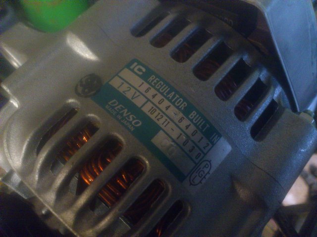
Description
Notice I have a P terminal - is that the same as Sense?
Edit - just found this -
"P Terminal on Denso Many Denso alternators used on industrial applications and/or utility tractors have a 3rd terminal that is identified as P,
shown in Figure 5. This is the same location of the S pin on most Denso regulators, thus a source of confusion and mix-up that should be paid
attention to and avoided.
Denso 101211-2941, equipped with a 126000-3480 regulator is one such alternator used on Kamatsu applications to watch out for. The P terminal is
actually a stator phase signal that can be used for various inputs to indicate that the engine is running, or it can be used to operate the tachometer
or other inputs such as the fuel shut off solenoid, etc. All of this said, it is of the utmost importance to have a functioning P terminal it must be
checked before the alternator delivery"
[Edited on 1/1/15 by davidimurray]
Gallery 1 http://www.facebook.com/media/set/?set=a.116893465324.130778.601005324
Gallery 2 http://www.facebook.com/media/set/?set=a.245243755324.181913.601005324&l=a9831a9319
Gallery 3 http://www.facebook.com/media/set/?set=a.440671625324.232627.601005324&l=3f0d42c523
Gallery 4 http://www.facebook.com/media/set/?set=a.490098255324.297598.601005324&l=efb083b7df
Gallery 5 http://www.facebook.com/media/set/?set=a.10150244028550325.366987.601005324&l=583fd5cd3a
Gallery 6 http://www.facebook.com/media/set/?set=a.10150550640070325.430417.601005324&type=3&l=fe779b358c
Duratec Engine Swap https://www.facebook.com/media/set/?set=a.10152527759580325.1073741828.601005324&type=1&l=40aae5e72f " target="_blank"> https://www.facebook.com/media/set/?set=a.10152527759580325.1073741828.601005324&type=1&l=40aae5e72f
|
|
|
davidimurray
|
| posted on 1/1/15 at 02:55 PM |
|
|
Well just cut the P connection and the light has now come on with the engine off. Will have to wait and see what happens when I get the engine
started.
Gallery 1 http://www.facebook.com/media/set/?set=a.116893465324.130778.601005324
Gallery 2 http://www.facebook.com/media/set/?set=a.245243755324.181913.601005324&l=a9831a9319
Gallery 3 http://www.facebook.com/media/set/?set=a.440671625324.232627.601005324&l=3f0d42c523
Gallery 4 http://www.facebook.com/media/set/?set=a.490098255324.297598.601005324&l=efb083b7df
Gallery 5 http://www.facebook.com/media/set/?set=a.10150244028550325.366987.601005324&l=583fd5cd3a
Gallery 6 http://www.facebook.com/media/set/?set=a.10150550640070325.430417.601005324&type=3&l=fe779b358c
Duratec Engine Swap https://www.facebook.com/media/set/?set=a.10152527759580325.1073741828.601005324&type=1&l=40aae5e72f " target="_blank"> https://www.facebook.com/media/set/?set=a.10152527759580325.1073741828.601005324&type=1&l=40aae5e72f
|
|
|