JoelP
|
| posted on 31/12/04 at 04:26 PM |

|
|
specifying a splined shaft
hi all. Just not wanting to sound stupid when i go into a machine shop in the near future!
so anyone know what specifies a splined shaft? is it just the number of spines, plus the inner and outer diameter? im guessing that another figure is
needed to specify the size of the splines.
i need to tell them what shaft i want so that i can connect a prop flange and a bike sprocket. much like an inverted sprocket adapter, or indeed a
sprocket adapter with a splined shaft thru it so that a sprocket can be added.
thanks in advance for any useful (or even useless but interesting!) answers.
cheers.
|
|
|
|
|
Peteff
|
| posted on 31/12/04 at 04:45 PM |
|
|
Take a sprocket in.
Ask them to make a shaft to fit it, sounds reasonable to me.
yours, Pete
I went into the RSPCA office the other day. It was so small you could hardly swing a cat in there.
|
|
|
JoelP
|
| posted on 31/12/04 at 05:50 PM |
|
|
smartarse...
i need to phone them, not go in!
[Edited on 31/12/04 by JoelP]
|
|
|
NS Dev
|
| posted on 31/12/04 at 06:03 PM |
|
|
Peteff it right, you'll really need to go there, or do a proper drawing, there are quite a few conventions that I know of, so there must be a
lot that I don't!!
When you say something like 1", 23 spline (i.e. type 9 ford gearbox input shaft) you are just identifying the "nominal identity" not
how to make the shaft. The angles of the faces of the splines vary from one spline type to another.
Beware who you go to for spline cutting as well, unless somebody already has the correct broach (pretty unlikely unless they are a specialist and
already aware of the spline type anyway) then it aint going to be cheap!!
The best way is to just use a common BS/DIN/SAE propshaft spline, which you can then describe by it's identity number. Look on here for the
info:
http://www.premierpropshafts.co.uk/index.php?id=1510
This company is just up the road from me, in Hartshill, near Nuneaton, and are very helpful.
|
|
|
JoelP
|
| posted on 31/12/04 at 06:32 PM |
|
|
the plan is, refering to the recent thread on twin bec cars, to make essentially a sprocket sandwich, with two diff flanges as the bread (not
literally a diff flange, just a plate with the holes drilled right). One to bolt to the diff, and one to bolt the propshaft onto. Id like the splined
shaft welded into on of the flanges, with the sprocket and the other flange bolted on.
once i get that step done i can then worry about a transfer box for the other engine. I keep thinking to myself im never gonna manage this, but thats
a loser attitude so im gonna try anyway.
so yeah, im thinking its probably burgess propshaft in bradford. I need to phone to see if its vaguely up their street, and then as pete says, take a
sprocket in (guess i shouldnt've take the pish!)
[Edited on 31/12/04 by JoelP]
|
|
|
Hellfire
|
| posted on 31/12/04 at 08:32 PM |
|
|
There are many, many ways of describing a splined shaft from the inner and outer dimensions to the effective diameter and the included angle of the
teeth, this together with root and top width of the teeth plus any clearance angles.
Best to take the part in to match it up... I'd say.

|
|
|
NS Dev
|
| posted on 1/1/05 at 12:57 PM |
|
|
I'm still not 100% with what you are trying to do, but I think I sort of understand. Can you not use the spline from the old sprocket, and just
machine the sprocket away to leave the spline behind, so you can weld it to your new flange?
I have done similar when adapting FWD gearboxes to mid engine transverse applications (I.e. my grasser...again!) I got the FWD CV joints, split them
at the line where the cage is friction welded to the splined forging, then got some sierra rear splined forgings (the ones with the abs ring on), and
cut off the 6 bolt flange plus a bit of the section that leads in to it, then turned steps on to both of them so they could be pressed together, held
the FWD splined section in the lathe chuck, and pushed the sierra flange tight and square up to it with the tailstock, then welded it up with it held
like that in the lathe (then a handy helper can turn the chuck very slowly and hey presto, roto-welder!) Just keep the slideways covered over to
prevent damage!
|
|
|
JoelP
|
| posted on 1/1/05 at 01:39 PM |
|
|
its a good idea, but it throws up some more problems - i cant remove the sprocket teeth myself, i would also still need a splined shaft to hold the
sprocket onto the flange. I would do away with the splined shaft and just weld it all up, but i also dont trust my ability to get it all lined up and
square. The shaft down the middle would help hold it all in place, plus if it was only bolted together i would also be able to replace the sprocket if
it wore out, without ditching the entire assembly.
im not sure burgess will be able to do the bits with the splined shaft but they definately supply the flanges drill to the correct bolt pattern. i
need to have a ring around this week. i
need to have a ring around this week.
|
|
|
JoelP
|
| posted on 1/1/05 at 01:46 PM |
|
|
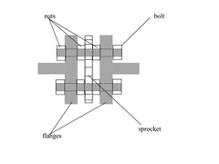
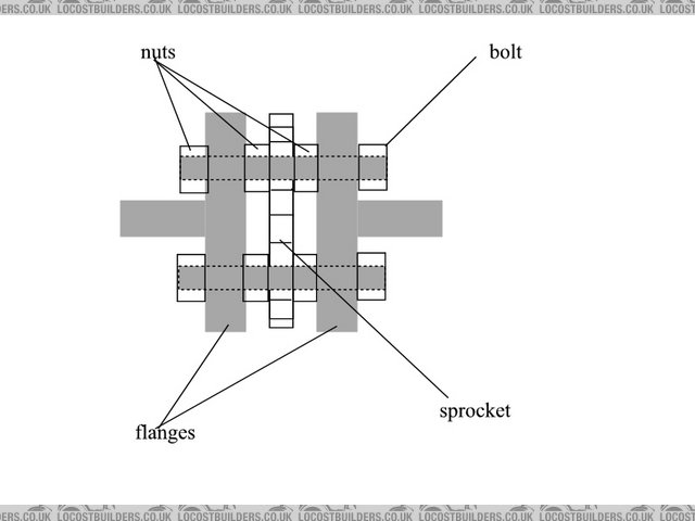
heres a basic picture. i really need to get a cad program!
actually, that pictures a bit misleading. it is a discrete unit, that bolts to the diff at one end and the prop at the other.
[Edited on 1/1/05 by JoelP]
 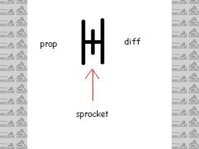
Rescued attachment sprocket sandwich.JPG
|
|
|
JoelP
|
| posted on 1/1/05 at 01:49 PM |
|
|
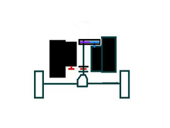
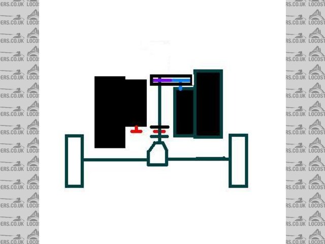
part of this overall scheme:
Rescued attachment twinbecmiddya.JPG
|
|
|
JoelP
|
| posted on 1/1/05 at 02:07 PM |
|
|
heres the lumps on a temporary frame, which i threw together to hold the engines roughly in place, to help with the
visualisation:s.jpg)
|
|
|
Peteff
|
| posted on 1/1/05 at 02:50 PM |
|
|
Why not drill the sprocket and bolt it to the face of the propshaft? You could space it out a bit with a plate or some washers. You could use
different toothed sprockets to vary the final drive ratio if you need to.
|
|
|
JoelP
|
| posted on 1/1/05 at 04:15 PM |
|
|
an excellent idea pete, the only trouble is that i *think* that the sprocket is actually smaller than the diff flange. then again, i guess i could
drill both...
the easiest approach is to simple buy 2 sprocket adapter, and then all i need to worry about is getting a spined shaft made up - not really that hard
by itself. The main problem is that two sprocket adapters would cost £100 at best, and im sure i can get them made up for a lot less. If i have no joy
making them, then i guess i'll have to buy them!
just imagine how much trouble i'll have making the front transfer box if im stuck on this bit! this is childs play compared to that...
|
|
|
Peteff
|
| posted on 1/1/05 at 05:10 PM |
|
|
Just had a look.
The 16 tooth sprocket off my engine is near as damn it exactly the same size as the flange on the propshaft. You would have to drill the holes
further in to miss the teeth but there's plenty of scope for that.
Rescued attachment adaptor.jpg
yours, Pete
I went into the RSPCA office the other day. It was so small you could hardly swing a cat in there.
|
|
|
JoelP
|
| posted on 1/1/05 at 05:17 PM |
|
|
i'll grab me brolly... off to the garage for a quick peek!
if your right and it works, then i could just skip the flange sandwich and just bolt the prop straight thru the sprocket to the diff flange, maybe
with a small plate to avoid having to drill the diff flange itself.
|
|
|
JoelP
|
| posted on 1/1/05 at 05:55 PM |
|
|
well, somethings not right! my diff flange (sierra diff?) is 4 inches round, my sprocket is 2.75 at the base of the teeth. seems no chance of drilling
them together. mines a 16 tooth one too. the fazer ones are a bit bigger, maybe 3 inches inside the teeth.
|
|
|
NS Dev
|
| posted on 1/1/05 at 10:57 PM |
|
|
Right, a very nice layout there, lots of nice ideas!
I think a man that might have a solution for you is Geoff Berrisford (yet again!)
He does a lot with chain drives and bike engines for class 8 and 10 autograss cars, making extension shafts and all sorts.
If you fax him a copy of your diagram he'll help you out, and I would say (off the top of my head) that it won't cost you much more than
the two adaptor flanges, I can't see a shaft with 2 bike sprockets and an output flange costing more than £200. He does shafts to any length
with sierra Lobro splines each end and heat treated, for £70 a piece.
His phone no. is 01270 841081 and his fax is 01270 841941. If you say someone from autograss racing has put you on to him I'm sure he will be
helpful.
|
|
|
NS Dev
|
| posted on 1/1/05 at 11:02 PM |
|
|
[Edited on 1/1/05 by NS Dev]
|
|
|
JoelP
|
| posted on 2/1/05 at 11:01 PM |
|
|
cheers fella, i'll throw something together and send him a fax.
|
|
|