Mansfield
|
| posted on 4/8/06 at 06:19 PM |

|
|
UDL beam deflection
Evening all, here's a good one for a Friday night.
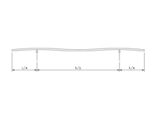
I am looking for values x and/or y for the diagram below to give me equal deflection at the ends and centre of the beam. The beam has a uniformly
distributed load.
I think these values exist without the need for E, I etc., and I am sure I have used them from a Machinery's Handbook about 100 years ago.
Can anyone help or suggest a website that could?
It's a build table related question.
Thanks, David.
Edit - poor punctuation
Edit - typo
[Edited on 4/8/06 by Mansfield]
[Edited on 4/8/06 by Mansfield]
 
Rescued attachment Image3.jpg
|
|
|
|
|
BKLOCO
|
| posted on 4/8/06 at 07:02 PM |

|
|
Machinery's Handbook
Chapter: Strength of materials
Section: Stresses and Deflections in Beams.
Case 5.
Both ends overhanging supports symetrically, uniform load.
Page 376 in my copy.
Unfortunately I don't have a scanner on my machine at work.
How anal is that?
Experience is what you get when you don't get what you want!!! 
|
|
|
Mansfield
|
| posted on 4/8/06 at 07:06 PM |

|
|
I really hope you are not working from memory BKLOCO, tell me you were looking at that page while you typed.
|
|
|
britishtrident
|
| posted on 4/8/06 at 07:08 PM |

|
|
Google for Bessel Points and Airy points
or just
http://www.mitutoyo.co.jp/eng/products/menu/quick_guide.pdf
|
|
|
Mansfield
|
| posted on 4/8/06 at 07:23 PM |

|
|
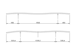
Using the support span as an average of Bessel and Airy points (0.558L) the drawing looks like this for a length of 2400mm.
Here is my drawing before and after new knowlegde, with dimensions.
I will have a look at Machinery's Handbook Monday to confirm.
Thanks, David.
[Edited on 4/8/06 by Mansfield]
 
Rescued attachment Image4.jpg
|
|
|
JohnN
|
| posted on 4/8/06 at 07:49 PM |

|
|
Is this an academic exercise, or is there a point to it?
Surely if you're building an elevated build table, you dont want any deflection, therefore 3 supports would be better than 2 (one in the
middle).
If the existing two were kept the same, this would increase the end deflections -
So what are the new support positions for 3 supports?
I'll check back later 
Personally, I'd run some 3x2 lengthways under the board?
|
|
|
Mansfield
|
| posted on 4/8/06 at 08:16 PM |

|
|
There is indeed a point to it. I have a price of £26 for a 8'x4' sheet of 25mm MDF delivered and I need to support it at a height of
750mm (I have a very small garage and need to store my locost gatherings underneath).
Length support advised, 40x40x2.5 RHS costs 2.40 + VAT per metre, I am trying to minimise the amount I need. Three supports would be better than two.
Four supports would be better than three. I need to assess the limit of supports - my first go weighed in at £80. Not Locost at all.
I have bought the 25x25x1.5 RHS now, there is no turning back - I need to build.
|
|
|
Mansfield
|
| posted on 4/8/06 at 08:25 PM |

|
|
JohnN, have you got any good pictures of your finished car?
I have often looked at your pictures and have been impressed.
Although I have the steel, I am still torn between +442 and +4 all the way through. I need decent sized seats, but the +4 looks 'wrong'
to me. The +442 looks nearer to 'right' but I have yet to see a finished car. I know this bears into a recent thread, but I would love
to see a proper finished +442.
What did you use a build table?
|
|
|
JohnN
|
| posted on 4/8/06 at 08:35 PM |

|
|
I built it on the floor, and when the chassis was part welded, lifted it up onto two trestles (no board).
My fibreglass scuttle & nosecone are Luego Velocity items, which I think were the tallest available at the time, it therefore has a certain
"bulk" to its side profile.
I'll put some more pictures of the finished car in my photo archive for you to look at.
John
|
|
|
Mansfield
|
| posted on 4/8/06 at 09:31 PM |

|
|
From your last post, you are saying a Velocity scuttle fits a +442 build - I didn't know that. I know the bonnet will need to be longer
(2" I guess).
The floor is not an option for me, its probably flat enough, but I need the best welding conditions I can get. I also need the storage.
I am looking forward to seeing your photos and I wouldn't mind betting I am NOT the only one.
Edit - missing the word NOT out of this post completely ruined the aim of the last sentence. So sorry. 
[Edited on 4/8/06 by Mansfield]
Edit - I am really quite drunk now, but I would LOVE to see your photos.
[Edited on 4/8/06 by Mansfield]
|
|
|
Chippy
|
| posted on 4/8/06 at 10:11 PM |

|
|
I supported my building board, 3/4", on two workmate, the very cheepest ones. (I think they were £15 each). Then placed two four foot lengths of
4 x 2 clamped in the workmates, with three lengths of 4 x 2 prepared timber under the board, leveled it all up, then screwed the whole lot together.
Very strong, very flat, and quite Locost.  Regards Ray. Regards Ray.
|
|
|
JohnN
|
| posted on 4/8/06 at 10:36 PM |

|
|
I cut the scuttle down the middle and widened it by approx 4 inches with a stainless plate, see photo in archive "scuttle gap cover".
I didn't alter the nosecone, it fits OK, width-wise, however, it doesn't cover the bottom suspension mounts, as it sits on the top chassis
rail, that is 2" higher than normal. I used the space below for a numberplate holder.
The bonnet is sheet steel made for the gap between scuttle and nosecone. point of note, a small, 1m x 2m standard sheet of metal is not big enough to
make the bonnet, it needs to be slightly wider than 1m, as although the approx. gap for the bonnet front to back is just under 1m, the plan shape
before bending is greater than 1m.
I've posted 3 photos tonight, I'll take and post more photos tomorrow.
[Edited on 4/8/06 by JohnN]
|
|
|
Mansfield
|
| posted on 5/8/06 at 10:53 AM |

|
|
Thanks John, Off to Shrewsbury 2.jpg is a nice shot. Your car looks very good.
I have seen that you have used Velocity rear bones, have you used Velocity fornts as well?
|
|
|
John Bonnett
|
| posted on 5/8/06 at 05:09 PM |

|
|
I have bought the 25x25x1.5 RHS now, there is no turning back - I need to build.
I am assuming the RHS is for the build and not the supports. I would have thought that ERW which is 16swg would be more than adequate, a lot lighter
and will cost a fraction of the price of RHS. It has been said within this Group (so it must be true!) that increasing the wall thickness has little
effect on the strength of the chassis. Apart from anything else RHS is a devil to cut with a hacksaw!
John
|
|
|
Mansfield
|
| posted on 5/8/06 at 06:42 PM |

|
|
The 25x25x1.5 RHS is for the build, I just need something to build it on now.
8'x4'x25mm MDF is £26 delivered, I am just trying to support it. I need the support in place for when it its delivered.
|
|
|
John Bonnett
|
| posted on 5/8/06 at 08:05 PM |

|
|
I wasn't trying to split hairs. I thought you were going to build using 3mm wall thick which is normally called rolled hollow section. ERW,
elecric resistance welded is 1.5mm, 16 swg wall thickness which is what most builders use.
|
|
|
Mansfield
|
| posted on 5/8/06 at 08:17 PM |

|
|
You are quite right, I have bought 36m of ERW. I was drunk last night, that does not excuse following the blunder through to today. Although I was
very hungover.
|
|
|
Confused but excited.
|
| posted on 7/8/06 at 03:18 PM |

|
|
If you want a cheap but flat working surface, why not make a stressed skin panel out of three sheets of 1/2" plywood. One top, one bottom and
the third cut into 4" strips, used on edge, to make the frame.
Screwed and glued it will make a really flat table top.
Tell them about the bent treacle edges!
|
|
|
DIY Si
|
| posted on 7/8/06 at 04:58 PM |

|
|
I made two supports and placed an old door on top. Then put the ply on this. It was strong enough to put the complete (ish) chassis on with engine and
box. I could even walk around on it with minimal difflection.
“Let your plans be dark and as impenetratable as night, and when you move, fall like a thunderbolt.”
Sun Tzu, The Art of War
My new blog: http://spritecave.blogspot.co.uk/
|
|
|


