
scratch build exoskeleton thread
drt - 8/12/13 at 02:00 PM
Hi,
Yesterday I was over the moon I could finally verify an email adress with LCB,
been reading for years  As from now I can join
  .
.
I'll keep it short,
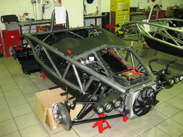
The car is of exoskeleton design and exist complete in cad.
Everything has been calculated and recalculated.
The problem I have... is that since I began building the frame months ago
the car reached MK999  because I can't settle on an engine/drivetrain
And keep redesigning everything everytime.
Parts of the project will also double as my thesis project,
So a gut feeling isn't enough to argument a choice upon 
Therefore I gathered and composed a list of 70 engine with specs
To choose through a set of demands.
I'm sure every builders goes through this, so I would like to hear about your experiences 
please.
I would be happy to share the list 
or the list of demands.
But this is a locost spirited build... so plentyfull and cheapish donors needed
MikeR - 8/12/13 at 02:16 PM
what fits, is cheap, can get through iva and isn't a nightmare to wire up - engine choosen.
drt - 8/12/13 at 02:34 PM
quote:
Originally posted by MikeR
what fits, is cheap, can get through iva and isn't a nightmare to wire up - engine choosen.
:p
okay, thanks. I will make at bit more specific.
demands;
*less than 500gbp
*space ? transvers I4, V6
*best p2w
*reliable
I've thrown a BEC out of the equation
they are still in the list (pre 1995 engines for IVA reasons)
Oh, and I was under the impression that if gearb and engine was used from a certain model,
this was tested to that vehicle emission specs?
list;
Wankel mazda12a
Toyota 3s fe
Alfa v6
RX8 renisis
Toyota 3s fe SC
MG F 1,8K VVC
MG F 160 trophy
Honda VFR750 rc36 BIKE
Honda B16B
Honda K20A
Honda B20A
Honda B18
Opel C20NE
Opel C20XE red top
VW 1,8T 20v
Subaru impreza 2.0 turbo
Toyota 2ZZ-GE(vvtli)
Toyota ZZ
Toyota ZZ 2.0
Toyota celica vvti
Toyota 3sgte (turbo
Rover 620TI
Kawasaki twin 750SX power
Kawasaki tuned twin 750SX power
Honda H22 2,2Ivtec
Peugeot MI16 1,9
Peugeot MI16 2,0
Peugeot Gti-6
Peugeot 1,9 8v
Peugeot s16
Honda CBR900
Honda TWIN CBR900
Honda TWIN CBR900 Turbo IC
Renault N7Q-704 2.0
Renault L7X 3.0
Volvo B4204T5
Volvo 850glt
Volvo 850 2.3T T5
Volvo 850 2.0 20v
Suzuki GSXR 1100
Suzuki RF 900
Suzuki GSX750F
Suzuki GSF1200
Suzuki GSF600
Ford ZETEC 1,8
Ford ZETEC 2,0
Honda CBR1000F
Yamaha XJ1200 1993
MG F 1,8
After demands etc I have the category winners...
Overall
MG F 1,8K VVC
Honda CBR1000F
Ford ZETEC 2,0
Rover 620TI
Peugeot 1,9 8v
Peugeot Gti-6
Opel C20XE red top
Honda H22 2,2Ivtec
Toyota celica vvti
VW 1,8T 20v
price
Subaru impreza 2.0 turbo
Peugeot Gti-6
Yamaha XJ1200 1993
MG F 1,8K VVC
Peugeot 1,9 8v
Volvo 850 2.0 20v
Honda B18
Honda CBR1000f
Honda VFR750 rc36 BIKE
Peugeot s16
p2w
Subaru impreza 2.0 turbo
Honda H22 2,2Ivtec
Suzuki GSXR 1100
Toyota 2ZZ-GE(vvtli)
Volvo 850 2.3T T5
Ford ZETEC 2,0
Renault L7X 3.0
RX8 renisis
Rover 620TI
Toyota 3sgte (turbo
and my favourite 
Bangs per Buck
Subaru impreza 2.0 turbo
Yamaha XJ1200 1993
Peugeot Gti-6
Honda CBR1000F
MG F 1,8K VVC
Volvo B4204T5
Rover 620TI
Honda H22 2,2Ivtec
Ford ZETEC 2,0
Honda B18
ali f27 - 8/12/13 at 03:04 PM
H I surprised no duratec mondaeos are common and no kv6
MikeR - 8/12/13 at 03:05 PM
zetec and mg engines have been used in loads of kit cars there for problems already found and parts required made. do you have time and money to
reinvent the wheel?
Ivan - 8/12/13 at 03:12 PM
I would go for the Subaru option -
+'s
It's Subaru  , low CoG, ample cheap power, fore and aft alignment, gearbox can be adapted to transaxle, reliable, relatively light I think.
-'s
Fuel consumption, width, gearbox length.
chrism - 8/12/13 at 03:31 PM
MGF might be a good option for a donor as all the hubs are already setup for double wishbone use and setup for rear wheel drive, so no hub mods to
make or adaptors required etc. Only issue is hubs have a slightly odd bolt pattern not one of the more common ones.
Plus also some people have swopped the Rover V6 engines into MGFs and they tend to be quite a good engine. (KV6 as mentioned above)
Subaru option is also interesting, but they do use the macpherson strut suspension so you would need to make some adaptors to change the top of the
hub to accept a balljoint at the front and bush at the back, unfortuntaely the design means you cant use mushroom adaptors like the sierra hubs, but
with the 4wd you could adapt the drive shafts to use the gearbox with the rear hubs for rwd and then cut off the CV joints on the front drive shafts.
drt - 8/12/13 at 04:23 PM
Hi guys,
thanks for the replys.
I came to the same conclusions.
the fixation is on the engine now, as hubs have been established.
I would also be running a quite wide track, so custom driveshafts I am stuck to anyway
And indeed I crossed out the Scooby because of the gearbox length.
I had some people telling me they -quite literally- hacked off the center diff and shortend it.
But have no data on how long it is then. (transaxle config)
The KV6 I like, the data I have suggest 170bhp and 155kg bare.
But they come with PG1 gearboxes, I heard they are prone to bearing failure
among the reason for doubting the 620TI despite the standard torsen diff
Duratecs are hard to come by cheaply (were I'm from)
[Edited on 8/12/13 by drt]
[Edited on 8/12/13 by drt]
Volvorsport - 8/12/13 at 04:27 PM
if you were going to fit a 20v NA volvo , it should be the 2435cc version rated at 163 hp. not the 2 litre 140 hp.
drt - 8/12/13 at 05:01 PM
updated the list...
with the Kv6 and duratec.
the formula states the top 3 as;
1.8K
zetec 2.0
kv6
(shame on me)
I do not know much about the KV6,
does anyone have dimensions (give or take)
Does it come with a lovely aftermarket like the zetec and 1.8K ?
and will the pg1 cope with the extra torque?
big_wasa - 8/12/13 at 05:54 PM
The kv6 engine is a great engine up to 200bhp. You will get just shy of this with just breathing mods. Induction and exhaust where taken direct from a
2L. They sound great and pull like a train.
They do have a few faults but Hgf is not one of them. Cam belts are a dear job and the tools are not cheap to do it your self. The balls on the
variable inlet manifold fail as do the viz motors. A new mani' is the best part of Ģ500.
Clutch hydraulics are cheap and plastic but there are ways around this with Honda parts.
The v6 pg1 is the heavy duty box and will handle the torque just fine. It can be upgraded with steel caged bearings and a Torsen diff.
Don't bother to try and get much more than 200bhp unless you have deep pockets.
I love the zetec but its done to death.
The Gti6 is a great engine but it leans back and that wont help weight bias in a middy.
I love the Scooby lump but it will add length to the car.
I am going to look towards the Volvo if I can find a cheap low millage car
drt - 8/12/13 at 09:35 PM
quote:
Originally posted by big_wasa
The kv6 engine is a great engine up to 200bhp. You will get just shy of this with just breathing mods. Induction and exhaust where taken direct from a
2L. They sound great and pull like a train.
They do have a few faults but Hgf is not one of them. Cam belts are a dear job and the tools are not cheap to do it your self. The balls on the
variable inlet manifold fail as do the viz motors. A new mani' is the best part of Ģ500.
Clutch hydraulics are cheap and plastic but there are ways around this with Honda parts.
The v6 pg1 is the heavy duty box and will handle the torque just fine. It can be upgraded with steel caged bearings and a Torsen diff.
Don't bother to try and get much more than 200bhp unless you have deep pockets.
I love the zetec but its done to death.
The Gti6 is a great engine but it leans back and that wont help weight bias in a middy.
I love the Scooby lump but it will add length to the car.
I am going to look towards the Volvo if I can find a cheap low millage car
Thanks!
Really nice, this is the sort of advice one can never have enough of 
rdodger - 8/12/13 at 09:43 PM
K series 1.8 VVC
Because.... Engine is very light, powerful and reliable. Yes reliable with correct installation, thermostat position, head gasket etc.
DVA power for more .... well POWER!
PG1 gearbox is also light, various Elise/Exige ratios available and final drives. Elise gearchange is going to be easy to fit. Uprated bearings are
readily available and not costly.
drt - 8/12/13 at 09:44 PM
btw,
a mate just offered his 'saab aero/viggen' opinion
Looks like a nice 150kg turbo lump...
...l'embarras du choix...
drt - 8/12/13 at 09:59 PM
quote:
Originally posted by rdodger
K series 1.8 VVC
Because.... Engine is very light, powerful and reliable. Yes reliable with correct installation, thermostat position, head gasket etc.
DVA power for more .... well POWER!
PG1 gearbox is also light, various Elise/Exige ratios available and final drives. Elise gearchange is going to be easy to fit. Uprated bearings are
readily available and not costly.
thanks,
you're absolutely right!
K series is still in the running.

drove a mates K series R300 (road going) few years back and loved it.
He also never had the HG issues.
But as 'absolute power corrupts absolutely'
I find myself pondering if I wont go the extra proverbial mile
MikeR - 8/12/13 at 10:02 PM
different thing to think of. most engines end up on the same side as the driver. engines as usually a lot heavier than the gearbox.
Some japanese engines are on the passenger side thereby potentially balancing things out a little.
(this is based on you driving on the left)
rdodger - 8/12/13 at 10:07 PM
Having owned a transverse mid engine car (GTM Libra. VVC) I would say the lighter engine/gearbox the better.
Roll oversteer is not your friend!
drt - 10/12/13 at 09:52 AM
quote:
Originally posted by MikeR
different thing to think of. most engines end up on the same side as the driver. engines as usually a lot heavier than the gearbox.
Some japanese engines are on the passenger side thereby potentially balancing things out a little.
(this is based on you driving on the left)
Very good point,
I will be looking into it right away
thanks
drt - 10/12/13 at 09:57 AM
quote:
Originally posted by rdodger
Having owned a transverse mid engine car (GTM Libra. VVC) I would say the lighter engine/gearbox the better.
Roll oversteer is not your friend!
vehicle dynamics wise weight is absolutely the enemy,
although COG of an engine can dial it out.
Butt I would suspect the double link rear suspension for that.
in the libra it is offset a little but instant centers will be on the floor.
Anyway, to make a judgement like that would require a great deal of study
and a complete data set on the libra... so maybe better forget I ever said anything 
drt - 10/12/13 at 10:04 AM
yesterday,
drove 250miles and picked up my hubs...
brakes...
and calipers...
and had to pass the 'r300 friend' to order some spherical bearings...
turns out he just bought an aston martin v8 vantage grrr

the noise it makes  hard to understand this is ECOG certified
drt - 15/12/13 at 04:25 PM
I recieved my 'tie-rod-ends' today
 Had a lovely price for them.
Decided to put off the engine choice...
But I'm still very interested in what expierences you all had with different engines...
like general breakdowns or total blow-ups 
In short what it is like to live with ... things numbers can't tell you.
Oh, and I have all the building/cad pics on photobucket... I'll post if anyone wants
rdodger - 15/12/13 at 04:31 PM
Yes get some pictures posted!
drt - 17/12/13 at 05:48 PM

The first building step


Getting tubes bent

laying it out
http://i819.photobucket.com/albums/zz120/motorsporteng/Home%20made%20Ariel%20atom/17_zps5985fea6.jpg
A rotisserie

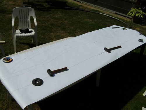
1:1 scale plans plotted of the main spar tubes


Family happy with the space saving stance


going for donor parts (fist batch)

last tubes


it is very roomy!!
rdodger - 17/12/13 at 06:59 PM
Brilliant!
As you say it's pretty roomy.
How much larger than an Atom is it? The sides certainly look to be higher?
What's the expected weight?
Do you have it drawn in CAD?
drt - 17/12/13 at 11:03 PM
Wel it is about 10mm wider,
the side is about the same, but as it is now i sit lower 
weight...
Started life as a BEC and was about 350-400kg.
now looking at car engis hope 490 as it looks now.
But I'll keep you posted.
The car is fully CADded up... everything from pipes to brakes from pedals to uprights.
most components were uptimiseded using FEM (FEA) (and a hefty safty margin  )
)
Friday I am machining the 'weld on suspension brackets'.
I have to make them myself as I am using metric tie rod ends...
And the haynes/champion style brackets are imperial ofc  so are he bushes.
drt - 17/12/13 at 11:04 PM
Oh and I TIG welded the whole thing...
wich was tedious... but welds are pleasing
iank - 18/12/13 at 07:02 AM
Hope that dressing gown is nomex 
Looking good.
drt - 23/1/14 at 09:56 PM
It's been a while since the last update...
Since last time;
Suspension brackets have been machined.
Tie rod ends delivered
Coilovers tested and measured up... choice pending...
because a huge discussion has arisen with my former suspension prof.
Hubs have been refurbished.
And...
I made an engine choice,
It was daylight robbery when I picked up a Saab 9-3 2.0T 
only 90K miles on the clock.
Standard low pressure turbo, hope to upgrade to something more substantial ...
But, it has the quite common gear selection problem... sorting atm.


[Edited on 23/1/14 by drt]
drt - 29/1/14 at 08:26 PM
Dear haynes,
I have loved and cherished your written words for years ...
But... with the Saab 9-3 codex...
you have completely and utterly got it wrong.
My improvements;
''when doing anything but a regular oil change or spark plugs on your Saab93
it is wise to sever your hands and attach on a large spanner.
Mind that a periscope is needed when wanting to see what you're doing while using
the 'hand-spanner'
If you do not have such a tool,
please go to chapter A1 to angle grind the car to bits"
drt - 14/2/14 at 01:06 AM
An update,
Suspension pivots nearly on.
Road wheels bought,
Custom set for slicks (just blind steelies)
Head skimmed, reassembling to test in the original car


drt - 24/3/14 at 09:36 PM
It has been quite a while since an update,
I apologize to everyone!
In the mean time I ordered some parts like;
nuts 'n bolts
engine parts
a short gearbox
electrics
tools
and made the wishbone (WIB) molds and started making the WIBs.

refitting the head

A front lower WIB, in its mold and pieced together

Stealing my welding table ? Well I'll just have to work in the kitchen than...

Drawing the WIB mold on the table and (center)punching it in.

A lower and an upper per table


A 800km return trip for a gearbox
drt - 26/6/14 at 04:24 PM

drt - 26/6/14 at 04:26 PM


drt - 26/6/14 at 04:34 PM
It has been a while 
In the mean time I've build a hangar, garage was just too impractical.
So now most of the work goes on in their (the neighbours love me)
I had craig from plazcutz reallise my cad pedal box design 
TOP Work  I'll get some pictures soon
The saab is running again and waiting for the transplant.
Once that is done I would want to fit an eaton, any comments on this are greatly appreciated.
Gaz shocks and springs are on the way
quick rack, steering wheel, lights,... on the way.
Finish all the molds and infusing is now the biggest step left.
snakebelly - 26/6/14 at 06:06 PM
Great minds think alike? or possibly fools never differ? We are currently converting our Tiger GTA to take a Volvo 1.9T with an Eaton :-) boy its
cramped!
Very impressive build so far, keep it up
[Edited on 26/6/14 by snakebelly]
drt - 27/6/14 at 12:22 AM
quote:
Originally posted by snakebelly
Great minds think alike? or possibly fools never differ? We are currently converting our Tiger GTA to take a Volvo 1.9T with an Eaton :-) boy its
cramped!
Very impressive build so far, keep it up
[Edited on 26/6/14 by snakebelly]
Thanks 
I can SEE the problem, the tiger engine bay is cramped for the volvo unit... full stop.
Please keep me posted on your conversion.
drt - 27/6/14 at 12:25 AM

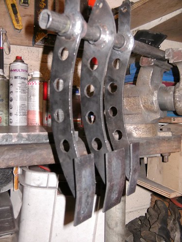
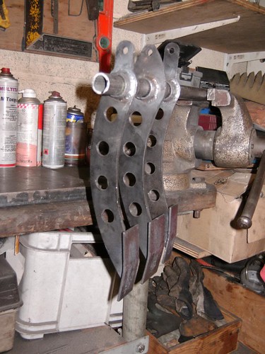
Here is the pedal box... well (a) I took them out the box... and saw them just laying around, so sad...
So...


drt - 27/6/14 at 12:49 AM
The move to the hangar (not making a lot chronological sense sorry)


rear suspension, the brackets are this big so in the future I could always go back to polybushes... not ideal.
But in the front this means the Caster can be set from 0 to 10° without inducing bump steer
(angled pick-up points would cause)


samjc - 27/6/14 at 01:23 AM
Coming along nicely. Like the pedals could do with making my own.
drt - 27/6/14 at 01:40 AM
quote:
Originally posted by samjc
Coming along nicely. Like the pedals could do with making my own.
I have the cad files if you wish,
Or contact plazcutz 
drt - 28/6/14 at 10:04 PM
I just love the postman... breaking his back on a non stop liveline of goodies 


Quick rack 

And front lights
cloudy - 28/6/14 at 10:36 PM
Steering rack look good - what's it from?
drt - 30/6/14 at 12:02 AM
quote:
Originally posted by cloudy
Steering rack look good - what's it from?
It is for a dirt style racer.
I could send you one  PM if interested
Very good price, but only 1 turn lock-lock... :s
[Edited on 30/6/14 by drt]
talkingcars - 8/7/14 at 10:51 AM
Sorry I am a bit late to the party but for the record.
Any K series engine (including the KV6) can be made to work as a mid or rear mount engine by using parts from the MGF for gear change linkages and for
clutch control.
The 2.5L KV6 from a manual ZT190 is 185 bhp, other versions in the ZT auto, ZS and freelander is 175.
drt - 24/7/14 at 04:49 PM
quote:
Originally posted by talkingcars
Sorry I am a bit late to the party but for the record.
Any K series engine (including the KV6) can be made to work as a mid or rear mount engine by using parts from the MGF for gear change linkages and for
clutch control.
The 2.5L KV6 from a manual ZT190 is 185 bhp, other versions in the ZT auto, ZS and freelander is 175.
As the say over here... take the next bus 
For now I will stick with the saab engine.
As it already has some pressure on it, installing a sprcharger will be easy-ish.
p2w isnt too bad.
But never doubt a minute that the roverK (and others) keep me up at night 
[Edited on 24/7/14 by drt]
[Edited on 24/7/14 by drt]
drt - 24/7/14 at 05:00 PM

Checking the Cad model of the 'hammock' with reality... using custom tools 


reality is a bit out 

goodies from RD 

Hammock mold

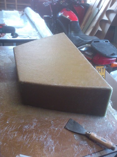
Later that night

Because of the shape, timber could be used for the sides... less sanding,filling and foaming

Finished...
Now a plug and then a finished article.
I would layer in alli strips to take the force while you get in/out the car...
This would save on materials,
any thoughts anyone ?
drt - 5/1/15 at 09:16 PM
It has been an absolute age!
Sorry for that, I have been busy.... busy...busy
But there is some news on the locost front...

It went on its wheels... but the bellcranks were flaud... made a bit of a scale fault.

Checking the measurements... both bellcrank, pushrod and damper must be in the same plane... a real pain on a curved car.

Harvesting the engine


Making engine mounts...

Next, the frame bracket

Very very tight fit

As in mm to spare

Had to tilt it a few degrees more the OEM... so the Diff would clear.

Gearbox mount... Bush mounted

Engine already leaving again... in order to drill the pivots for the bellcranks...
I'll make some pictures of the mounts in the future

Ofcourse in a very tight spot... this is just for the pilot hole, the rest was drilled through from the other side.
Also, the seats are in !

Hybrid driveshafts... waiting for welding

The new bellcranks !
coozer - 5/1/15 at 09:34 PM
Good work fella, just noticed this thread and I have another spoiler for ya..
Did you not consider a VAG engine? I'm taken with using a BAM 225 Audi TT or Cupra engine in mine, already 225bhp. 170 easy with a chip, good for
over 300bhp standard...
drt - 5/1/15 at 09:45 PM
quote:
Originally posted by coozer
Good work fella, just noticed this thread and I have another spoiler for ya..
Did you not consider a VAG engine? I'm taken with using a BAM 225 Audi TT or Cupra engine in mine, already 225bhp. 170 easy with a chip, good for
over 300bhp standard...
thanks, :p I did look at the VAG engine. They are quite expensive over here :s And when you find one, its mostly the 150bhp version.
Keep me posted  And if you get the change, put it on some scales !
I might reconsider
drt - 23/3/15 at 09:28 PM
Work is a bit slow, as I am full-time on the drivetrain of a hypermiler vehicle for competition 
A bit sad, but who needs sleep if spring is in the air... and 1/2 car in the shed...

Making the fuel tank (will be baffled)

Fuel tank fits lovely

Centering the hybrid driveshaft

New Seats in place !!! Really glad with these, as they will fit my royal behind, are still quite light and offer good support.

looks cosey, even with the non-removable ford wheel you can get in and out. The would walk way is to simulate the car's bottom

New pivots... finally

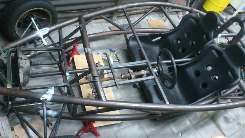
I can barely see where to put my feet ^^... this would work... but there is no real space for the steering column... especially because the pedal box
will be moveable.

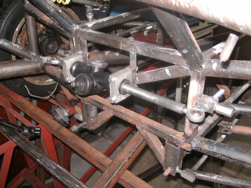
This Servo is SO big  it's a bit of a problem... I am thinking of buying one from a small citycar (vivio) because they are 160mm in diameter
instead of this 250mm whopper, although as these things work on engine vacuum... servo action will be compromised :s any suggestions ?

Original selector

reworked selector... non essentials had to go...

Tube will house electrics etc... shifter cables will come from beneath the seats  it was the only option

The sitck will need some more length... shame I didn't build the seat bench myself... then the selector could have been closer  Something for
the Mk2
scudderfish - 23/3/15 at 09:38 PM
Why not just ditch the brake servo? I reckon most of the cars on here don't have one.
peter030371 - 24/3/15 at 08:23 AM
quote:
Originally posted by scudderfish
Why not just ditch the brake servo? I reckon most of the cars on here don't have one.
What he said 
drt - 24/3/15 at 02:52 PM
I can see your point(s)
:p
I had the argument with myself, and several people...
If you do not instal a servo you have 2 choices (obvious sorry)
1) huge travel and low (required) pedal force
2) huge pedal force and small travel
Even if you would vary the master cilinder piston diameter
I have a autograss buggy thing, and although it only weighs 390kg you really have to STOMP it
if you want some stopping power... so much so that I am not able to heel-toe in it.
I know most -if not all- kitcars,locost do not have a servo...
So hom much pedal force do you have to exercise ?
peter030371 - 24/3/15 at 04:30 PM
My previous experience of a non-servo'd Striker (circa 530Kg plus me and the passenger) over 18 years of use is that a firm pedal pressure is
required but I could heel and toe and I could lock the wheels if i got a little carried away/ over excited on the track  The feedback was very good
without a servo and I would have hated to have lost that 'feel'.
My current Striker still has not got an engine or brake fluid so no idea if that is worse or better 
drt - 24/3/15 at 06:37 PM
Doing the maths comes up with 35.77Kg of foot pressure during 1G braking (idealized)
Sounds like a lot ?
piston diameter 0,048 m
Displacement brake pad 0,002 m
vehicle weight 500 kg
Braking 9,81 m/s^s
Braking torque, ideal brake distri, 1 wheel 927,936 Nm
Brake friction coeff 0,35
Saab 93 brake master cil bore 0,0238 m
pedal ratio 4,89
Mean brake disc radius 0,19 m
n number braking surfaces 2
Brake pad surface 0,005 m^2
Brake pad force 6976,962406 N
Pressure on brake piston 963904,5614 pascal (N/m^2)
force needed on master cilinder 1715,291053 N
Displaced volume brake caliper 3,61911E-06 m^3
Needed master cilinder displacement 0,813501871 cm
pedal displacement @ foot 3,97712026 cm
Pedal force @ master cilinder 174,8512796 kg
Pedal Force @ foot 35,76503446 Kg
coozer - 24/3/15 at 06:56 PM
Good work, just a quickie, how you going to route gear cables, water pipes and whatever round the fuel tank? Over, under or to the side?
Are you running the water pipes down the centre? That's assuming the rads going to the front?
Steve
drt - 24/3/15 at 07:26 PM
quote:
Originally posted by coozer
Good work, just a quickie, how you going to route gear cables, water pipes and whatever round the fuel tank? Over, under or to the side?
Are you running the water pipes down the centre? That's assuming the rads going to the front?
Steve
Gear cables are going over, electrics to the side (away from exhaust) and water... wel
I was planning on sticking a rad in a pontoon... and the intercooler on the other side.
Thus choosing mass centralization over ideal weight distribution.
scudderfish - 24/3/15 at 07:38 PM
quote:
Originally posted by drt
Doing the maths comes up with 35.77Kg of foot pressure during 1G braking (idealized)
Sounds like a lot ?
piston diameter 0,048 m
Displacement brake pad 0,002 m
vehicle weight 500 kg
Braking 9,81 m/s^s
Braking torque, ideal brake distri, 1 wheel 927,936 Nm
Brake friction coeff 0,35
Saab 93 brake master cil bore 0,0238 m
pedal ratio 4,89
Mean brake disc radius 0,19 m
n number braking surfaces 2
Brake pad surface 0,005 m^2
Brake pad force 6976,962406 N
Pressure on brake piston 963904,5614 pascal (N/m^2)
force needed on master cilinder 1715,291053 N
Displaced volume brake caliper 3,61911E-06 m^3
Needed master cilinder displacement 0,813501871 cm
pedal displacement @ foot 3,97712026 cm
Pedal force @ master cilinder 174,8512796 kg
Pedal Force @ foot 35,76503446 Kg
Assuming you weigh circa 70-80kg, that is about the force you feel on the sole of your foot when you are standing up.
drt - 24/3/15 at 07:51 PM
Assuming you weigh circa 70-80kg, that is about the force you feel on the sole of your foot when you are standing up.
I'll take that as a very optimistic compliment ^^
drt - 27/3/15 at 11:53 AM
So, I'm dumping the servo 
thanks for the tips!
Now, this is the master servo.
How would you link that up? As the shaft does not describe a straight movement (due to pedal... etc etc you know)
A shaft with a 'spherical' end (ball) could work, but i'm scared about radial force on the plunger.
Because the saab converts the movement before the servo to straight (linear).

peter030371 - 27/3/15 at 12:29 PM
They normally have a clevis pin on the end but not sure how you would fit one to that master cylinder.
drt - 3/7/15 at 08:22 PM
During these last months I have been busy with our uni's ecomarathon team pushing 700 hours since February... besides normal classes...
Not a lot of time for personal indulgences 

Machining the brake shaft so it works without the servo

finished product

A lot more room now XD


In the meantime trying to get the molds done... this is the airscoop


And this the bottem of what is going to be the bonnet mold

An overview, Thinking of housing the rads and IC over there  ... mass centralisation and shorter water/air lines

Because of my geometry, this is the only spot the rack could be in :s


Bonnet mold almost there

And a delivery of brake stuff
drt - 14/7/15 at 01:48 AM
I've been waiting for news from RD for weeks 
So, I'm doing detail work... front lights tonight


And the girlfriends car needs attention...

drt - 15/7/15 at 12:01 AM
Today... a day of angry phone calls
...rear lights
...and setting up the rotaxmax for a week @ Spa (promised the misses 'spa' don't think she really gets it though XD)

drt - 11/8/15 at 11:13 AM

So a whole week at the Spa Karting  25°-30°C and mostly dry.
Now she needs a top end rebuild, anyone knows somewhere I can get rotaxmax parts cheap ? Over here it's 500 smackeroonies... because you can only
let it be done.

Build a small furnace... I got her up to over 1000°C, now i can cast my own ally parts.
First use was to make a ring for my girlfriend (had to make up for the Spa thing)... :p Silver is surprisingly easy to work with! and under the
current raw silver price it was very cheap ^^

I have been waiting months for Rally design parts... really wondering if I would still place my orders there, the costumer service is a trainwreck.
Anyone having problems ?
To top it all I ran out of Argon, and over here all building sector and related companies are closed for a 3week builders holiday... no gas for me
then.
Easing the pain with turning a gearknob


Thinking about using the Saab mirror glas in a DIY side mirror... because they are heated  making life so much better when it's cold or starts
to rain...
if they only weren't so vast.

Engine is in for the xxxxtime
drt - 11/8/15 at 11:25 AM
Oh, I have been meaning to ask.
The original atom uses separate front parklights/daytimerunninglights...
Looking at the model they are crystalight ?
If so, they only sell reversing lights... who would be way too bright/diffuse to pass an iva :s
Anyone knows what they are ?
see->

drt - 11/1/16 at 11:16 PM
It's been a while


testing the look in real life for the first time... before starting making the molds and ultimate products


vast amounts of resin, glass- and carbon weaves arriving along with corque sandwich material... postman sure loves me :p

sanding all the wood models for the last time before the varnish coat(seallent)

making parts for new steering arms... as the original ones had dreadful Ackermann, even without the change in wb and track


For a long time I was planning on using an LED as an reserve fuel warning light, just by adding resistors so that when the float reaches zero (aka
lowest resistance) the power in the circuit would be +- 5v... a very simple, light and elegant solution... but turns out LED's aren't as
picky as I thought... the lit up as soon as 1.5v  getting ever brighter,
too bad... have to stick in a gauge

And then this disaster, I was planning on using the Saabs fuel pump as a piggy-back on my tank... turns out a Saab has just the one pump in the
tank.
Thus it has internal passages to avoid air bubbles (it's a rotary pump, can't suck air) These are impossible to close of, so can't use
the pump outside the tank... need to use the whole original plastic nightmare or buy a specific new one.
Keeping it locost by reworking the tank so to use the original.
This needs a bigger hole and bigger lowest fuel gathering compartment.

needed to go to, because of packaging the fuel nozzle is moving to the other side

To add to all that, I've just ordered jet cutted parts the week before; So I'll make the pump fitting the old fashioned way

The lid

the new set up, not very pleased with this

My tank is much higher than a Saab one, so this had to be lowered to
Now I'm waiting for some quite days to do all the composite work in one go
drt - 14/1/16 at 12:59 AM
took her out to clean the hangar

peter030371 - 14/1/16 at 08:11 AM
Looking good, we have all sat in our chassis at some point and gone 'brum brum' 
drt - 14/1/16 at 01:20 PM

Getting very eager to get to do it for real 
jimmyjoebob - 14/1/16 at 05:28 PM
Build looks great - what make are the seats you are using and how much do they weigh?
drt - 1/2/16 at 11:26 PM
quote:
Originally posted by jimmyjoebob
Build looks great - what make are the seats you are using and how much do they weigh?
Sorry for the late reply.
I got the seats here;
,2 x BLACK BUCKET SEATS. PLASTIC 4x4 kitcar, beach buggy, Boat.
Very good service ! very good seats... I must warn that they are BIG...
much much bigger than the GFRP's I had (kitspares type ones).
But fit me very nicely !
But you'll need some space in your vehicle.
I didn't weigh them yet, the fabricator states 7.5kg a pop.
drt - 17/2/16 at 12:20 AM

repositioned the gear selector again, somewhat higher and more back... much more ergonomic and now with a tiny throw

postman came by

I couldn't help myself XD

love the sound dampening qualities

I don't believe you guys have this in the uk ? Cheap as chips! and works so good... it could strip the grease of a steam engine

the end of another late night

spot the pun... it was only a matter of time this washed up

After a lot of careful cutting and consulting the cad model...

exhaust completed... now only wait for 2 Vbands to come in and weld it all up
drt - 17/2/16 at 10:17 AM
tips on how to polish the dull stainless pieces to suit the mirror finish of the damper, please do not hesitate 
drt - 4/3/16 at 01:24 AM

Who needs a lasercutter when you have a nice angle grinder


The new gearselector in place, I'll be adding some structure to it later to give it lateral stiffness... and remove the now obsolete parts
drt - 3/4/16 at 10:42 PM
I have been busy with a lot of things, in the meantime I did the gearshift (gearbox side) pics will follow... and placed the radiators...
This might be surprising


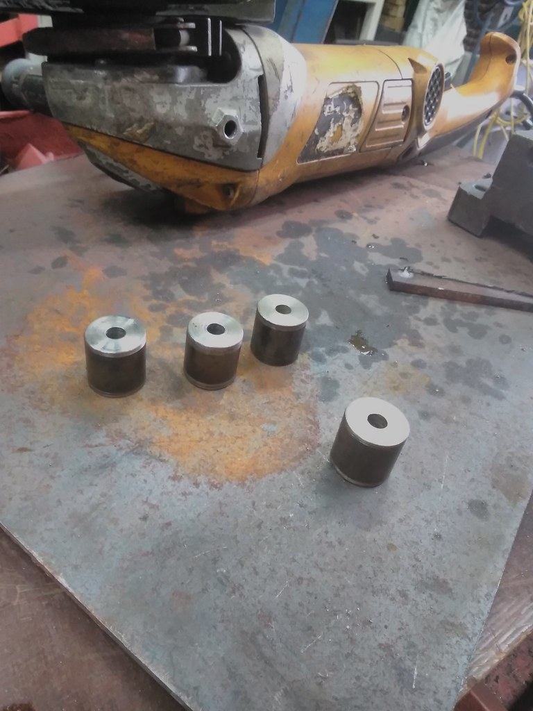
SO... I machined some spacers to make a Rad Sandwich... these fit the plastic bobbins on the rad, the same system applies to the suspension of the
sandwich.
I prefer it that way hance the small (4mm ish) screws in the plastic are now only in tension instead of in shear like with most :s
Also the plan to put them in the side pontoons got scrapped... pontoons needed to be way to big, so now the'll house the inter- and oilcooler.
drt - 2/5/16 at 12:18 AM
The Gear selector... I ended up buidling models up to MK3,
MK1 being direct action... but in the friction/stiction-less world of CAD these things work, in reality it was one big jam.
MK2 being the picture below with a direct acting push/pull for sideways motion and a non rotationally fixed mount for in/out motion.
Because of space restrictions (exhaust) the motrion could nog be lineair ... locked up yet again because of friction and created moment on the gear
shaft... thus binned
MK3 Is this one, using a lever action directly in line of the required force for in/out movement.

Had to lathe a thingy to attach the tie-rod-end center shaft


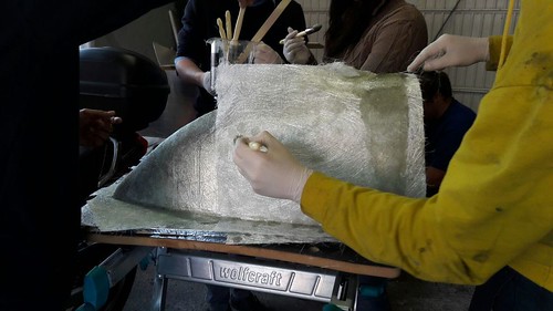
AND WE STARTED LAMINATING...
Tricking a large part of the family in participating


We started with the "hammock" between the front wheels
Despite using several coats of boat lacquer on the wood model... and sever coats of PVA some parts still bounded 
It was hell getting her out... destroying the model in the process.
For the other models I'll be using my secret weapon.

drt - 3/5/16 at 09:25 PM
We continued these last days with laying up the mold on the model of the ībonnetī.
This one needed a double amount of layers to make it stiff enough..
That meant tapping, tapping and more tapping...


Luckily I have some reinforcements...
In this shot the 'secret weapon' is visible... insulating aly tape

Works a charm, out in 10 minutes

a mirror finish

And even the model survived unscratched this time

And because of the team effort I had to make a task black board... very 6sigma
drt - 7/5/16 at 01:09 AM
Taping the hammock model


A very flash gordon airscoop model

drt - 15/5/16 at 08:32 PM
Today we've build an airscoop mold


It's a real family affair...very thankfull of that! it means we can make a mold in a few hours... the banter, that's free

shouting how things should be done... running in the family

drt - 25/7/16 at 01:11 AM
itīs been quite a long while...
my TIG broke down, wtf paid nearly 3000 quid for it only 5 years back ! Been dry+warm stored and only used on the weekend.
Ofc they wouldnīt tell me what was wrong, had to wait 2 moths for the damn repair.
So starting where we left off...

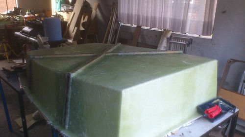
The mold for the nosecone

Hammock mold

making th mold stiffer, as it is quite big. This was a real faff !!! The resin would not stick to the wood and spur bubbles all over, drove me
insane

So this was the result, ugly as fa... but it does the job...
It got to me so bad that Iīm splashing cash to do the īproductsīby vacuum injection.

And this is thanks to ma genius... an old motorcycle fuel tap now serves as a 3way valve for getting argon to the TIG, the weld piece or both.

Because we're finally tigging the stainless bits

With the help of some lathed wood

This almost doesn't look like a huge bodge

As by magic... Tadaaaa finished

And then I made a new tank out of ally, as the steel one weighed a tonne.
Since I only rarely weld ally I was quite pleased... and then I saw Project binky yesterday... one can only cry

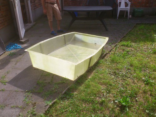
This morning we started demolding the hammock... again a moment of terror... despite using the ally tape making the surface so smooth that even the
PVA cant be polished up because it rubs strait off... and ofc the PVA who's only goal in life is to DEMOLD the damn thing... it would not come
out for sh*t.
Again a model had to be destroyed

3hours of blood sweat tears and curses got it out
drt - 26/7/16 at 02:20 AM
anyone any tips on polishing stainless exhaust? ally tank ?
drt - 27/7/16 at 12:51 AM
some time ago I was asked how I would run the cables, cooling etc in the car.
well, I've created this...


For the water I've chosen to run a pipe through, I had considered running it directly... but didn't trust the fuel acting as an
accumulator.
shifter cables and wires are going through also.
Lately we we're having an itch epidemic, with everybody moaning and scratching S. Holmes came to the conclusion the problem was the wash cycle in
conjuction with GFRP 

 The culprit was punished to very old fashioned laundry days...

drt - 6/8/16 at 12:45 AM

So the tank is in...

I adapted the brace to be bolted... I'm foreseeing a tie rod end connection in the future, but for now...
So the tank rests on the brace and is strapped to it. Sideways movement is halted by little brackets on the frame.
Now just need to paint it and then find some self adhering foamy bits...
drt - 5/9/16 at 11:20 PM
So in the meantime a lot of sanding molds...
I really despise doing it, but anyhow not a very informative picture for you guys XD

Tonight finished the gearshift... best throw ever, about 30mm :p

Downside is that the selector needed a bit more stiffness...
The opening is needed to reach the connectors, will give it a think how to stiffen that part. As obviously this is now the weak point

The shifter end... looking at it from behind... remember that the Saab has a rod acting directly upon a shaft while I now have a cable selector...
So I needed to invent this from scratch

A rod end pulls and pushes the shaft via an adapter that als has an arm for the rotary motion.
The push-pull cable for the rotary motion is hung by a pivot as the in/out motion of the shaft is far greater than the cable would allow.

drt - 5/9/16 at 11:27 PM
Last year I spent August on the track...
this year could not have been more different, though still had wheels 

sprintB+ - 6/9/16 at 07:46 AM
Good to see you back, I did wonder where you had gone. excellent work, well done, keep us posted
drt - 6/9/16 at 10:33 PM
Thanks sprintB+
btw I have found some products for the anglegrinder to polish stainless and ally 
Sundaydriver - 18/9/16 at 11:42 AM
Great thread, loving your efforts, I'll check in again 👍
drt - 18/11/17 at 02:53 AM
[img] 1[/url
] by [url=https://www.flickr.com/photos/141082768@N04/]paris r, on Flickr[/img]
[img] 1a[/
url] by [url=https://www.flickr.com/photos/141082768@N04/]paris r, on Flickr[/img]
[img] 2[/u
rl] by [url=https://www.flickr.com/photos/141082768@N04/]paris r, on Flickr[/img]
[img] 3[/u
rl] by [url=https://www.flickr.com/photos/141082768@N04/]paris r, on Flickr[/img]
 4
by paris r, on Flickr
 5
by paris r, on Flickr
 6
by paris r, on Flickr
 7
by paris r, on Flickr
 8 by
paris r, on Flickr
 8a by
paris r, on Flickr
 11 by
paris r, on Flickr
 11a
by paris r, on Flickr
 12 by
paris r, on Flickr
 14a
by paris r, on Flickr
 15 by
paris r, on Flickr
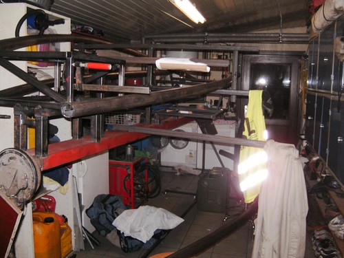 17
by paris r, on Flickr
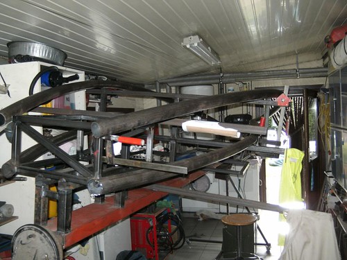 18 by
paris r, on Flickr
 19
by paris r, on Flickr
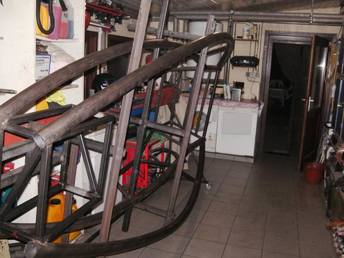 20 by
paris r, on Flickr
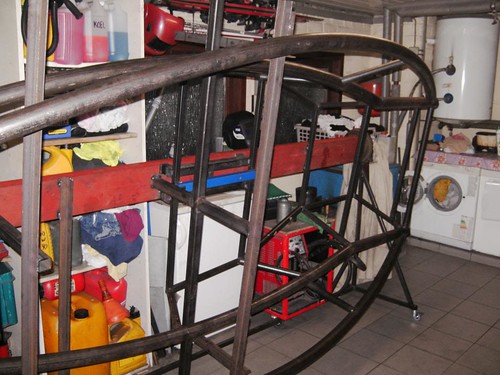 21
by paris r, on Flickr
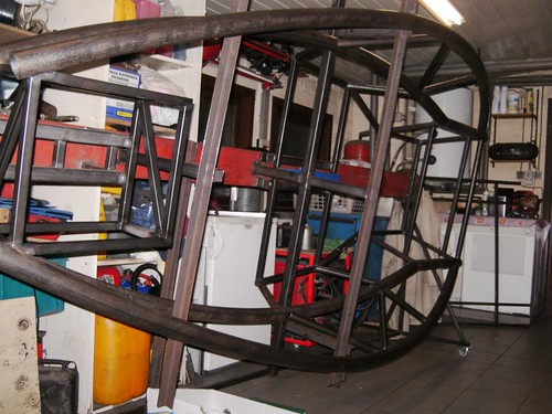 22 by
paris r, on Flickr
[Edited on 18/11/17 by drt]
drt - 18/11/17 at 03:08 AM
 24 by
paris r, on Flickr
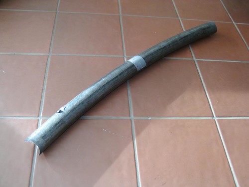 25
by paris r, on Flickr
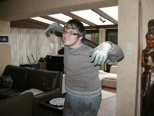 26
by paris r, on Flickr
 27
by paris r, on Flickr
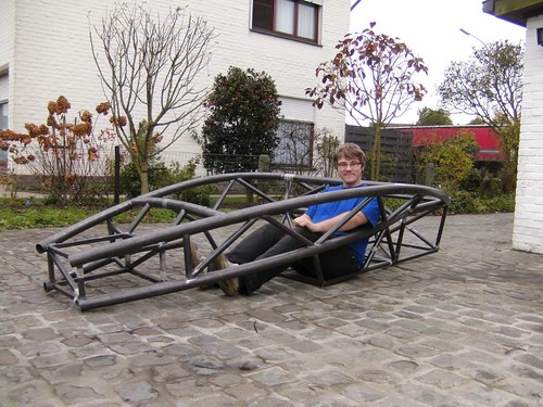 30
by paris r, on Flickr
 36
by paris r, on Flickr
 37 by
paris r, on Flickr
 38
by paris r, on Flickr
 40 by
paris r, on Flickr
 41
by paris r, on Flickr
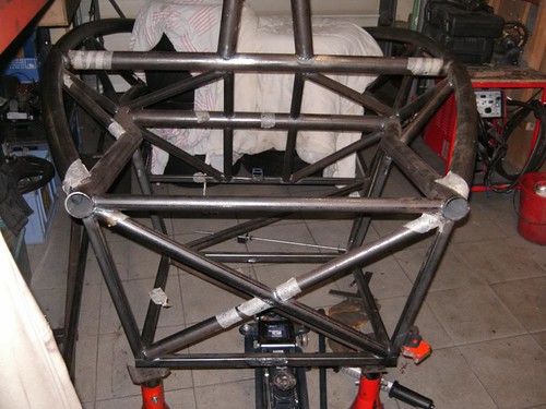 43 by
paris r, on Flickr
 44
by paris r, on Flickr
 45
by paris r, on Flickr
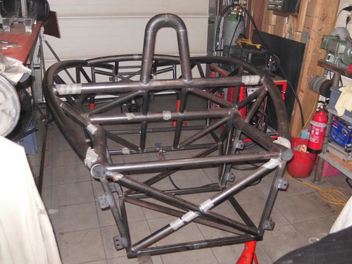 47
by paris r, on Flickr
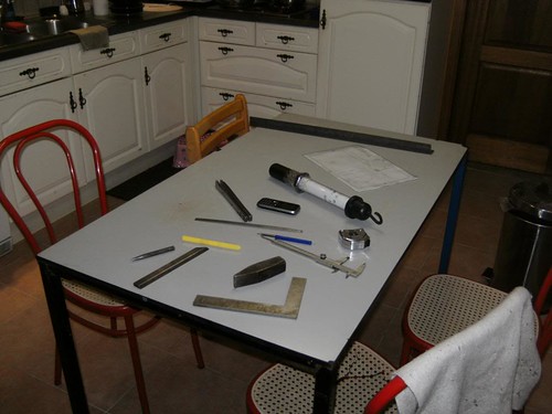 48
by paris r, on Flickr
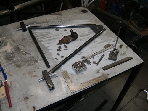 49
by paris r, on Flickr
 50
by paris r, on Flickr
 51
by paris r, on Flickr
 52
by paris r, on Flickr
 56
by paris r, on Flickr
 57
by paris r, on Flickr
 58
by paris r, on Flickr
 59
by paris r, on Flickr
 60
by paris r, on Flickr
 61
by paris r, on Flickr
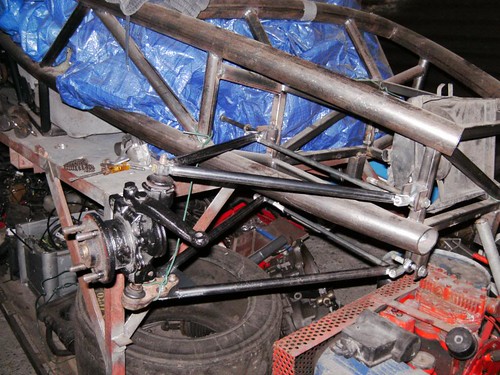 62
by paris r, on Flickr
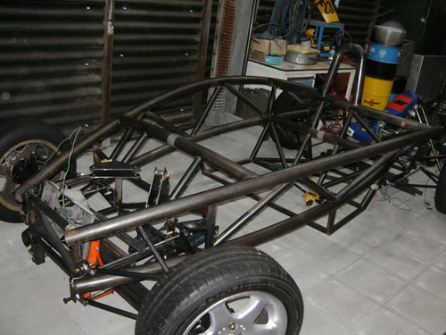 67
by paris r, on Flickr
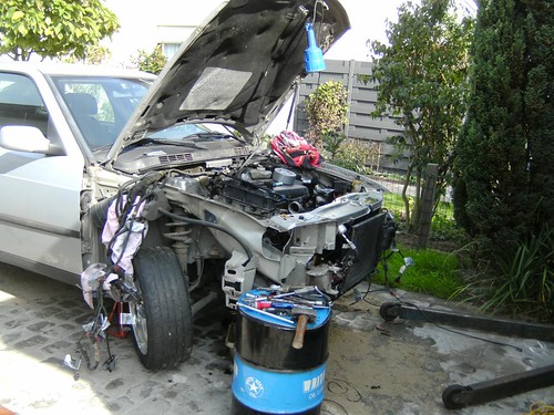 72 by
paris r, on Flickr
 74
by paris r, on Flickr
drt - 18/11/17 at 03:10 AM
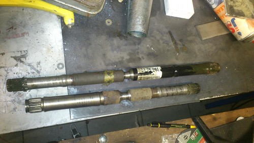 75 by
paris r, on Flickr
 76
by paris r, on Flickr
 77 by
paris r, on Flickr
 78 by
paris r, on Flickr
 79
by paris r, on Flickr
 83
by paris r, on Flickr
 85
by paris r, on Flickr
 86
by paris r, on Flickr
 87
(1) by paris r, on Flickr
drt - 18/11/17 at 03:14 AM
 87
(2) by paris r, on Flickr
 88 by
paris r, on Flickr
 89 by
paris r, on Flickr
 90 by
paris r, on Flickr
 91 by
paris r, on Flickr
 95 by
paris r, on Flickr
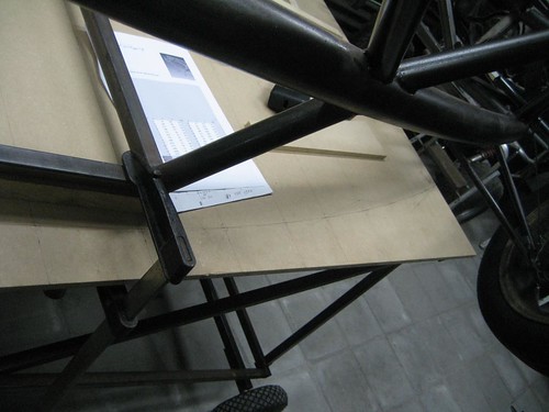 96 by
paris r, on Flickr
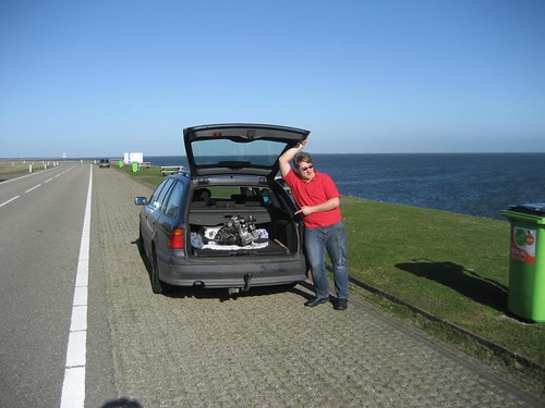 101
by paris r, on Flickr
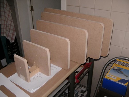 102
by paris r, on Flickr
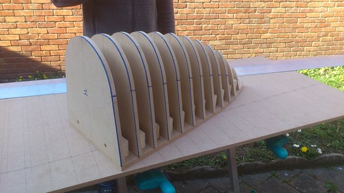 103
by paris r, on Flickr
 104
by paris r, on Flickr
 105
by paris r, on Flickr
 106
by paris r, on Flickr
 107
by paris r, on Flickr
 108
by paris r, on Flickr
 109
by paris r, on Flickr
 111
by paris r, on Flickr
 115
by paris r, on Flickr
 116
by paris r, on Flickr
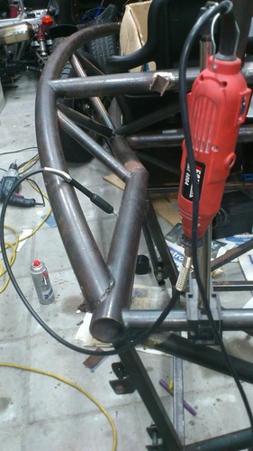 117
by paris r, on Flickr
drt - 18/11/17 at 03:17 AM
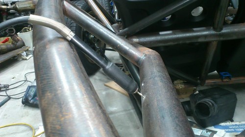 118
by paris r, on Flickr
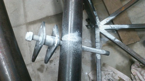 119
by paris r, on Flickr
 121
by paris r, on Flickr
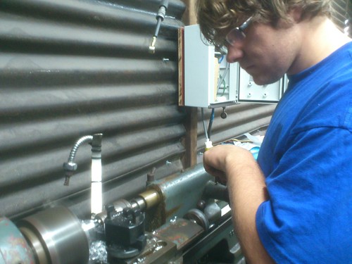 124
by paris r, on Flickr
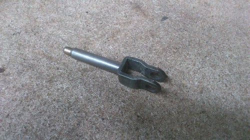 126
by paris r, on Flickr
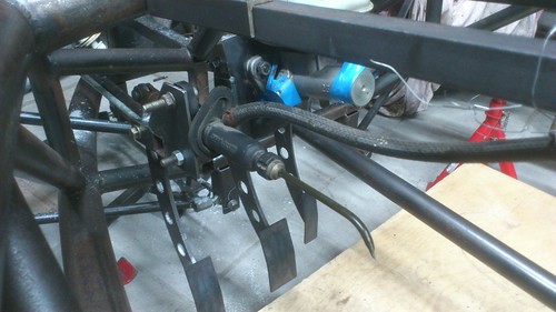 129
by paris r, on Flickr
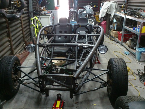 133a
by paris r, on Flickr
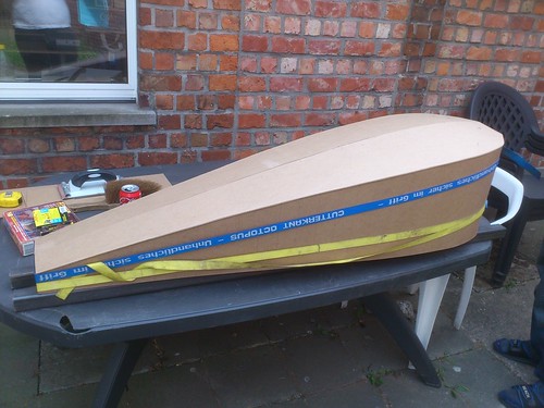 134
by paris r, on Flickr
 135
by paris r, on Flickr
 136
by paris r, on Flickr
 138
by paris r, on Flickr
 139
by paris r, on Flickr
 145
by paris r, on Flickr
 147
by paris r, on Flickr
 151
by paris r, on Flickr
 152
by paris r, on Flickr
 154b[/url
] by [url=https://www.flickr.com/photos/141082768@N04/]paris r, on Flickr
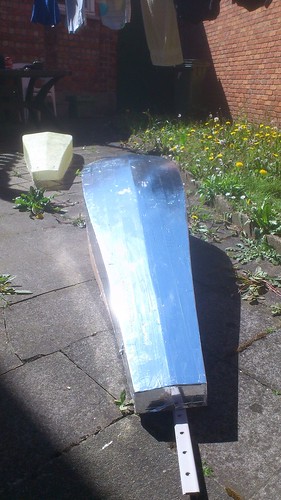 155
by paris r, on Flickr
drt - 18/11/17 at 03:20 AM
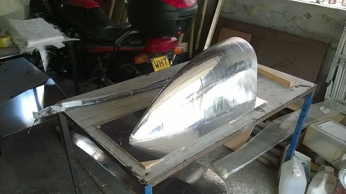 156
by paris r, on Flickr
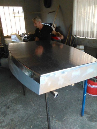 157
by paris r, on Flickr
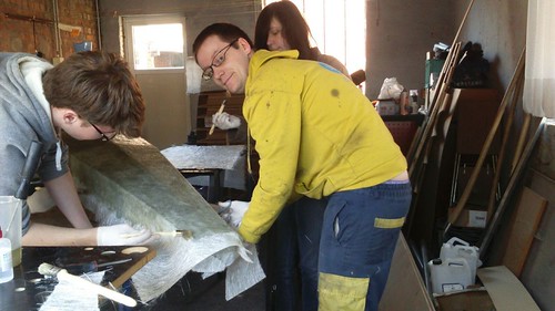 158
by paris r, on Flickr
 159
by paris r, on Flickr
 162
by paris r, on Flickr
 168
by paris r, on Flickr
 174
by paris r, on Flickr
 172
by paris r, on Flickr
 175
by paris r, on Flickr
 177
by paris r, on Flickr
 180
by paris r, on Flickr
 181
by paris r, on Flickr
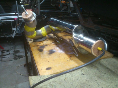 184
by paris r, on Flickr
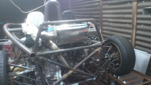 191
by paris r, on Flickr
 186
by paris r, on Flickr
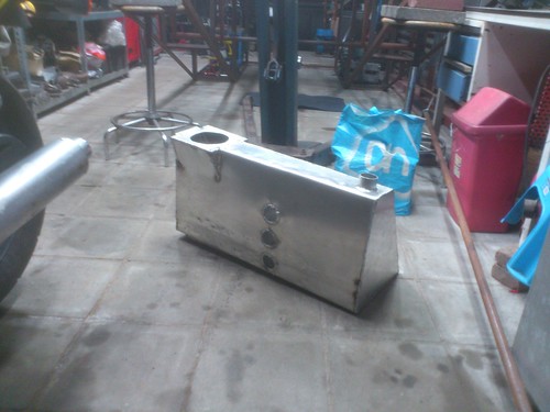 188
by paris r, on Flickr
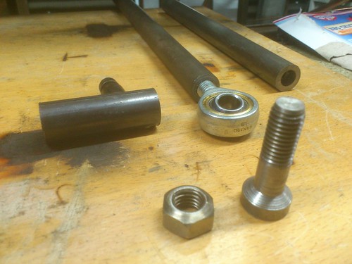 189
by paris r, on Flickr
drt - 18/11/17 at 03:34 AM
Well, thanks for that photobucket... no new stuff gents.
I have had the worst 2 years of my life...looking for internships trying to graduate.
Monday I have an interview with Prodrive, any help welcome.
Also still without a car since looking to be an (unpaid) intern means little dosh coming my way and it didn't help that the tax regime for the
daily I was doing up went up by a 1000% (no joke) 3 weeks before I finished it, so started from scratch with another daily.
meanwhile the Saab engine has left the shop.
Over the summer the company that made the ECU interfaces for the TRIONIC disappeared, so that meant that for it to run in the Atom I would had to
invest in a standalone ECU thingymabob...
and despite what the guys at MCN say, an Emerald does noet a budget build make.
And the engine was too heavy anyway, since it's becoming abundantly clear that this rotten country will never let me have it on the road.
So it needs to be a 750kg trailer/car combo so I can tow it to the track... leaving about 500kg ish for the car.
So I looked for -and found- the best engine ever made
 191
by paris r, on Flickr
A rover K
I would like to put bike carbs on it ( multiple reasons) but I guess I'll keep it standard till I get it running
[Edited on 18/11/17 by drt]
big_wasa - 18/11/17 at 07:32 AM
Now if that donor had the 2.5 kv6 that is indeed a cracking engine.
drt - 18/11/17 at 11:41 AM
Srr mate...
just a 4 pot...
:p current budget, total weight and dynamic reasons.
kitman - 3/12/17 at 08:05 PM
Are you putting it on the road when it's finished?
ettore bugatti - 3/12/17 at 09:38 PM
Good choice!
Original Atom was also build with the K-series.
drt - 4/12/17 at 01:30 PM
I'd love to put it on the road, but it seems mine is the worst country in the world for such a thing.
So euhm I have a little route around the leg.
Thanks I always loved the roverK, it should bring me to -500kg now... that will allow me to trailer it (750kg)
drt - 14/1/18 at 10:24 PM
So
Finally started on extracting the K-series...
And doing other stuff in the lid workshop during the long evenings.
For the sake of honesty ... when I designed the car I never had never seen the uprights but had parametric kinematic designs for the placements of
pick up points... in my stupidity I guesstimated the location of the steering arm.
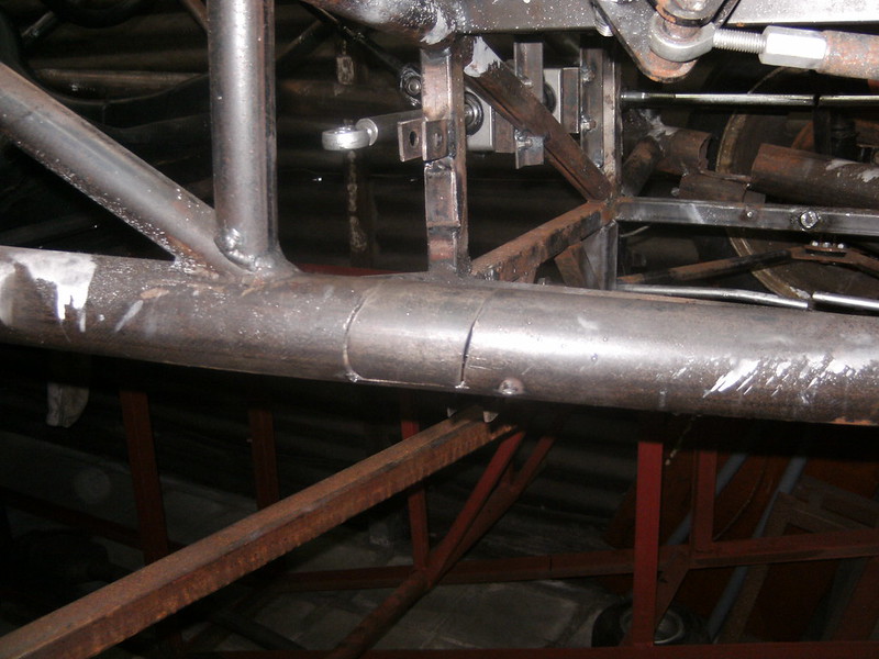
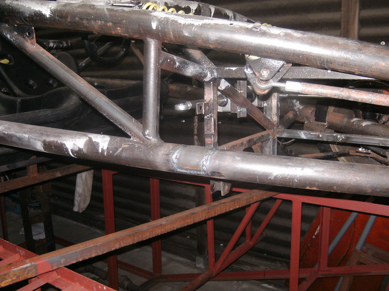
And that bit me in the ass as later appeared that the only bumpsteerless route was through the chassis member 
FFS
[img]
[img]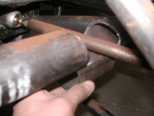
Because of the top A arm interfering I can only reinforce the bottom and cross brace above... a bodge... But I can see no other way
drt - 14/1/18 at 11:33 PM
Why so little progress ?
In 2017 me and my daily where taken of the road by a hit and run.
With no funds I set out to get a cheap daily, had to restore one in the end.
Finished I was faced by sudden a 10 fold road tax increase and was priced out.
Sold it at the original price despite the resto because the market had caught on to the tax regime.
With only commercial vehicles exempt from the tax man (yeey capitalism) I had to try for a van...
A T4 was the only thing reliable and in budget... well in this state
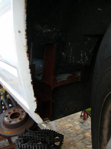
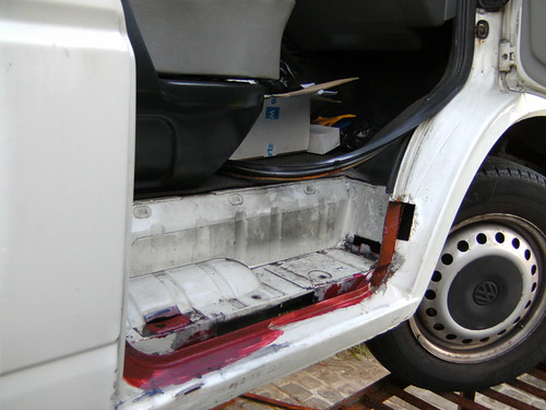
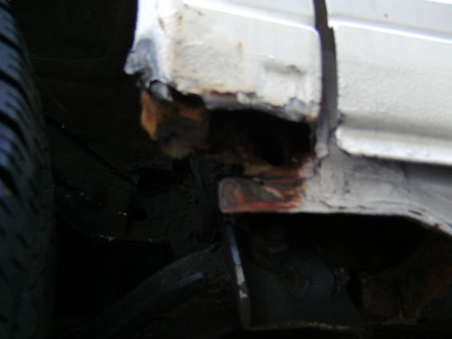
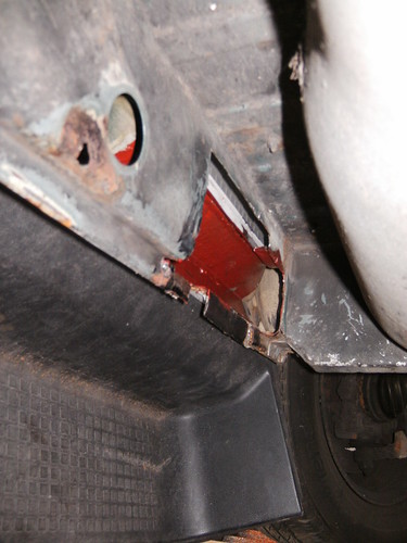
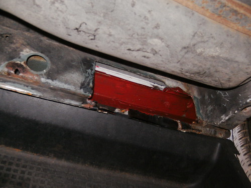
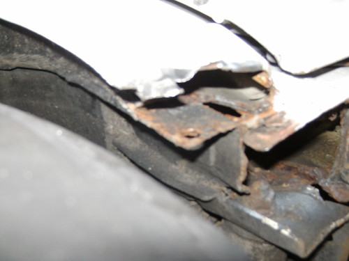
So on top of that new brakes, turbo, suspension, bumper beam, back garden respray, fuel pump and other weld work ... we're mobile once again.
2017, I won't miss thee
drt - 22/2/18 at 09:10 PM
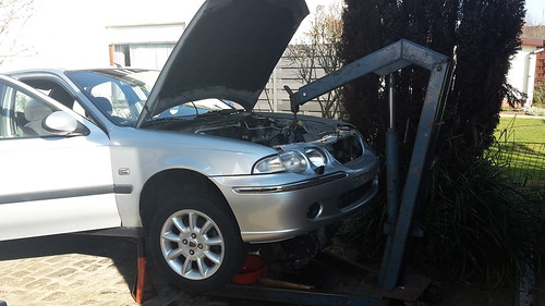
Engine out today
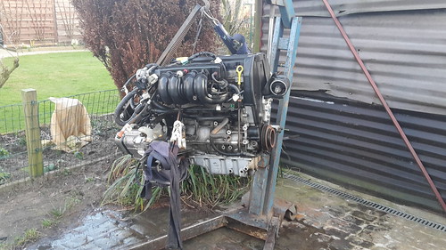
After cleaning
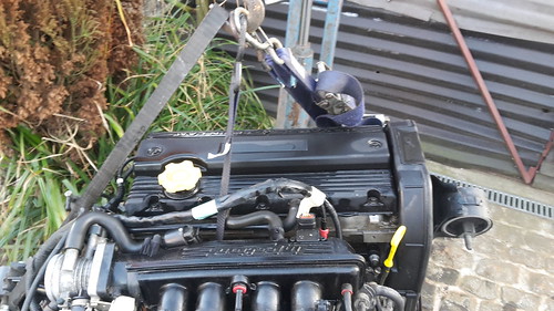
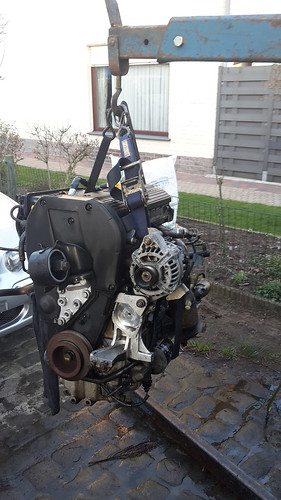
threw away the ancillary's... now how to route that alternator ?
drt - 15/3/18 at 10:15 AM
So, the alternator bracket thing for a non-AC set up arrived.
In the process of fitting the engine...
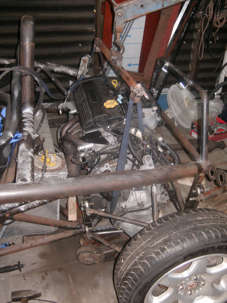
I was a bit gobsmacked that the roverK is bigger than the saab B204/205 !!
The belt drive camshafts are a cause I presume, but in all rover choose toe make the engine wide and low, while the saab's was fat, high and
narrower
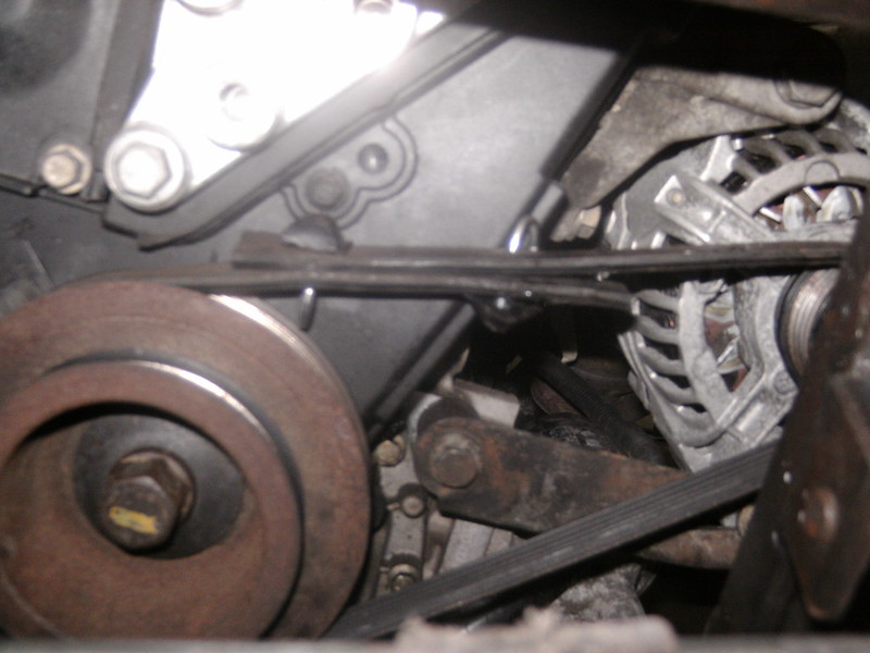
I don't get why people buy new belts, works fine
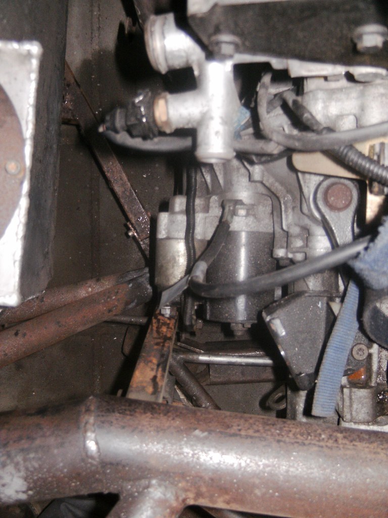
Starter position is not helping me
drt - 12/4/18 at 10:42 PM
soo putting in the RoverK in...
I was getting worked up about having to weld driveshafts again so decided to tackle the suspension issue first.
because -those who followed- there is a large chasm in the front chassis member to let the steering arm go through.
The only solution is to give the suspension a parallel geometry, since then I can move the rack around without causing bump steer.
So I was gonna go for that... screw the camber comp...
Since that meant I might had to redo the wishbones I was thinking to narrow the track (1600mm now) to accommodate the
OEM rover 45 (track=1475mm) wishbones
(saving me that heart ache as well)
BUT i stumbled upon the most wonderfull thing!!!!!!!!!!!!
While trying to fit the driveshafts it became clear the rover 45 CV's wouldn't fit the MGF hubs.
Crying out loud I -while swearing- fitted the MGF CV's on the Rover shafts... and lo and behold...this combo apparently takes the track to
1590mm
So problem solved since there is enough adjustment in the current wishbones and in the gearbox side CV.
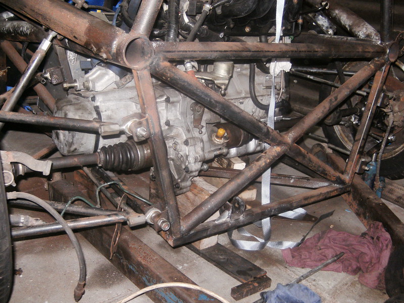
So now making new suspension pick-up points
drt - 16/5/18 at 03:45 PM
Ok so nobody impressed by the wideness of the rover MG combi driveshafts...
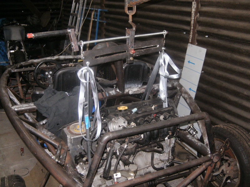
Been trying to fit the engine for weeks... but keep struggling to find the best compromise.
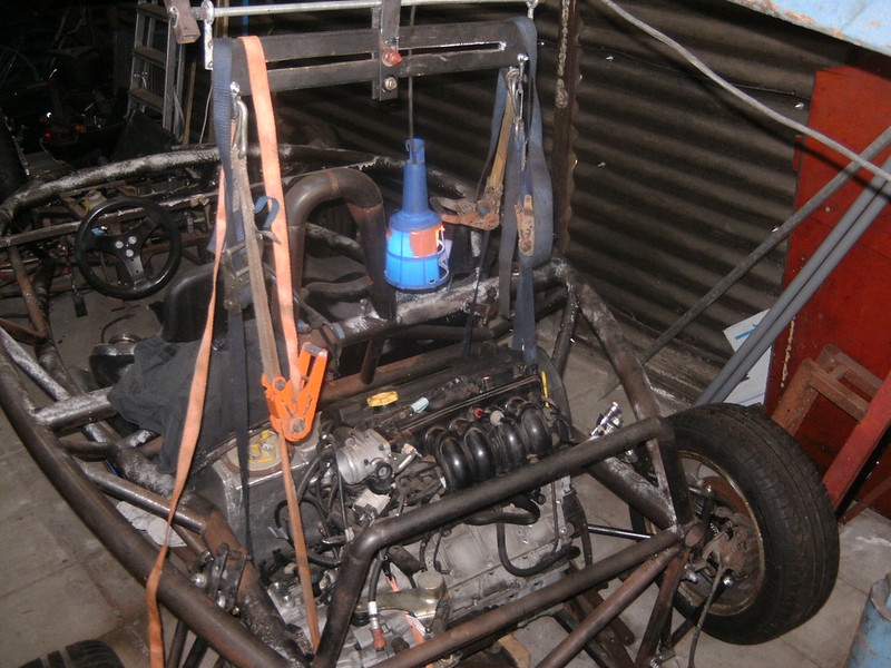
The more you know the less you know, it's a curse
Bodged a load spreader bar the easily level the engine.
Still added 4 ratchet straps to change the inclination on the go.
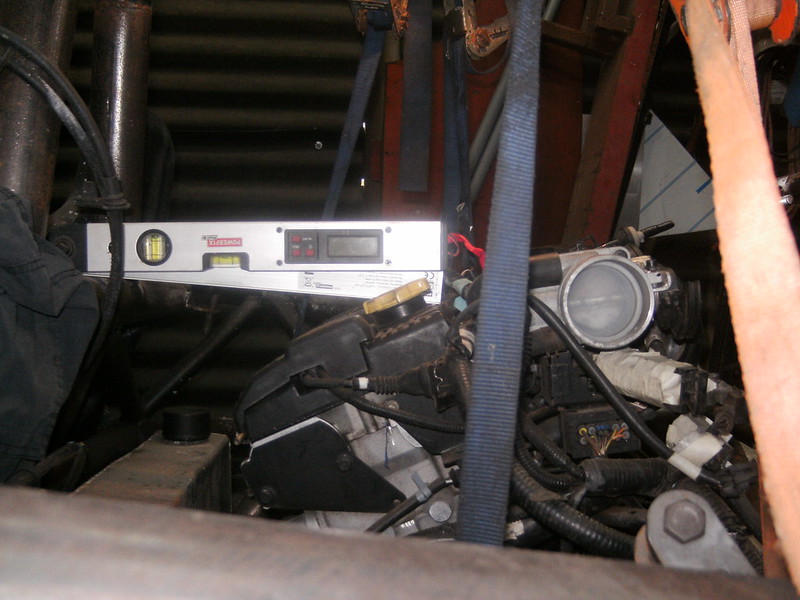
But now not sure about how the engine will take the angle
drt - 19/5/18 at 12:02 AM
So I went with the 11.1 degrees in the end...
Finally started fitting...
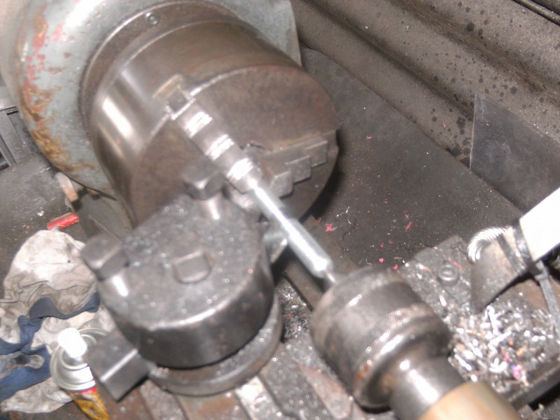
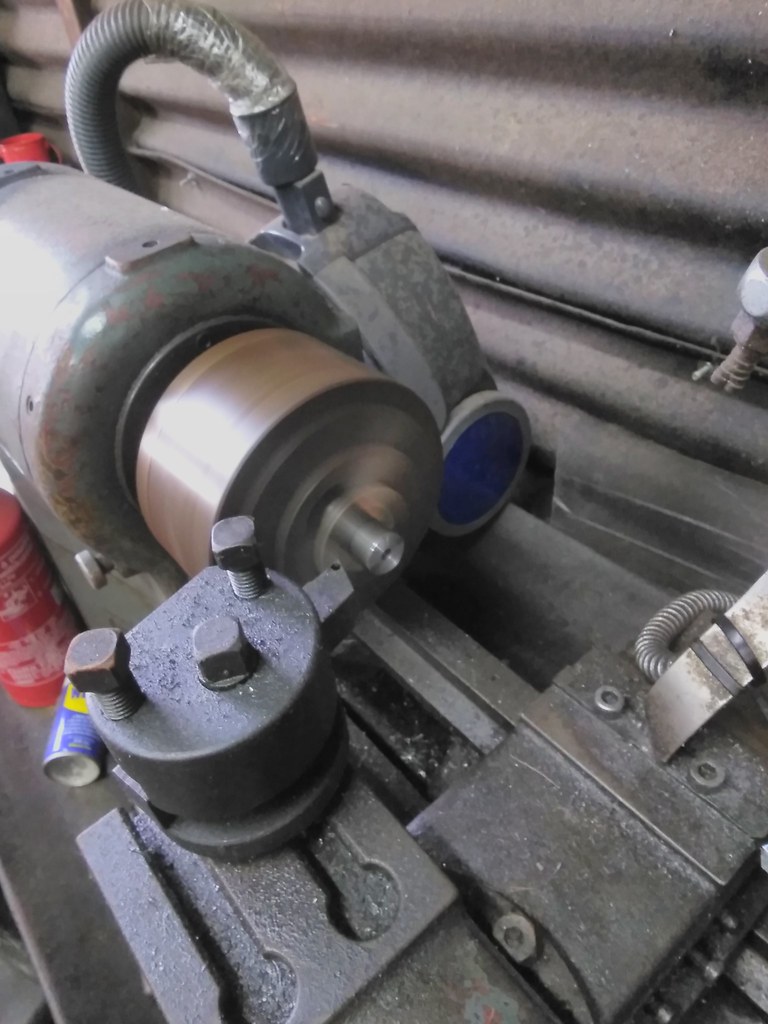
Machining a stud with M12 thread on one side and M10 smooth+threaded on the other
Why?
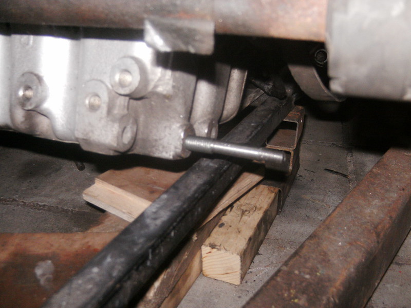
So it will fit the engine and the take the bushings I have
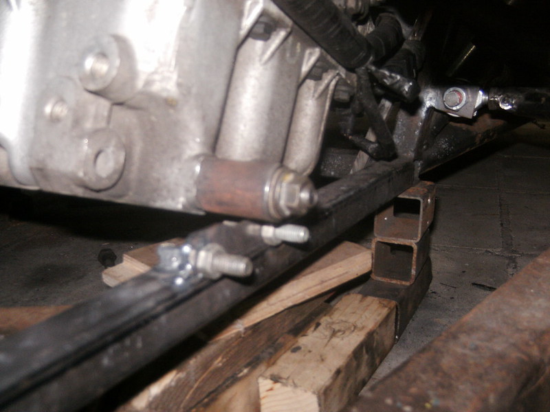
After much consideration decided to fit the bracket this way as it was easiest to (re)fit an engine this way
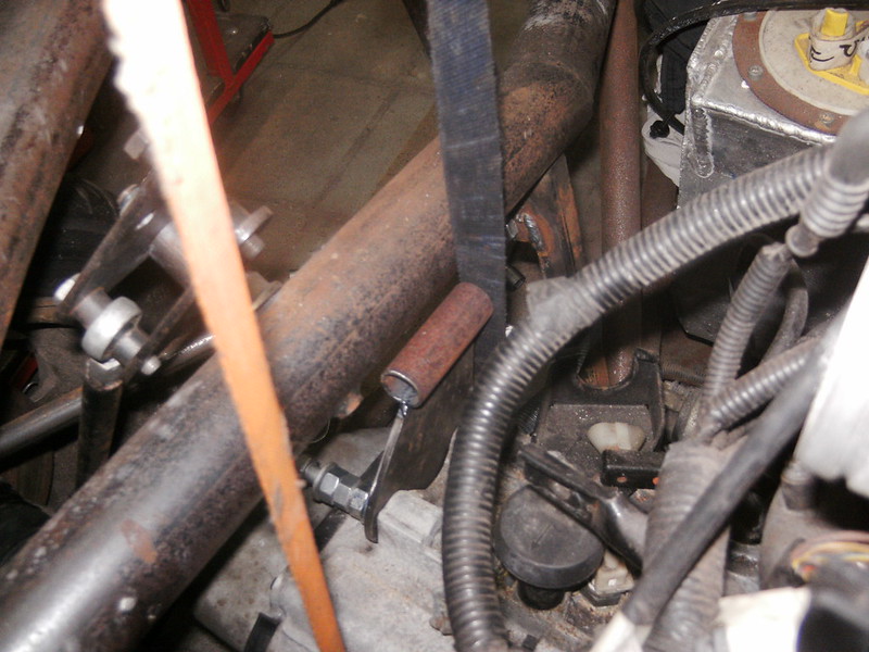
Gearbox side
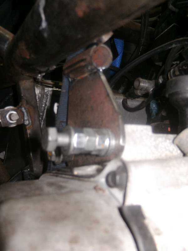
Going ...nuts... doing these bolts up 20 times an hour
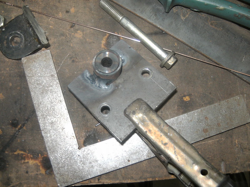
Lower mount tagged on in situ and now being welded fully.
A machined steel bushing temporary takes up the space of the rubber one... makes fabricating much easier and beats burning rubber
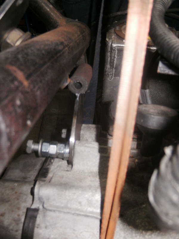
Gearbox side fully welded and rubberised
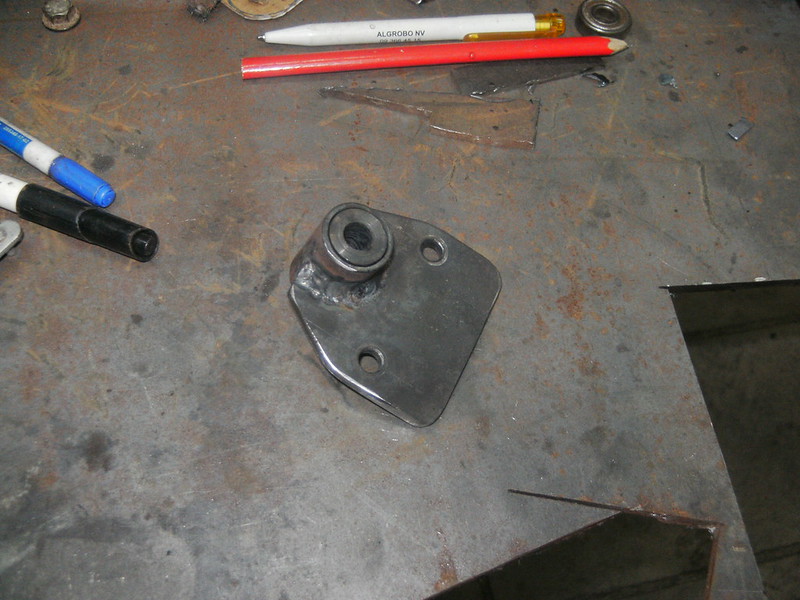
Lower side finished
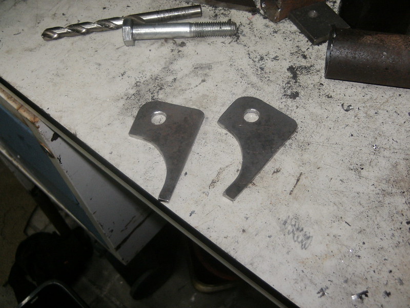
Gearbox side brackets... who needs a laser cutter anyway
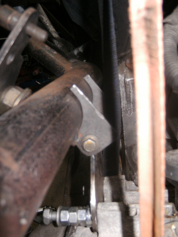
Like zoo
Started on the third and fourth engine mount... more on that tomorrow
drt - 23/5/18 at 12:00 AM
A little word on the engine mounts...
I see a lot of people use the PU tophat type suspension units, and those are waaaay to stiff to filter any vibration.
Even so if you do the arithmetic, given the frequencies of an engine and a stiff light frame, it is very hard to isolate the one from the other.
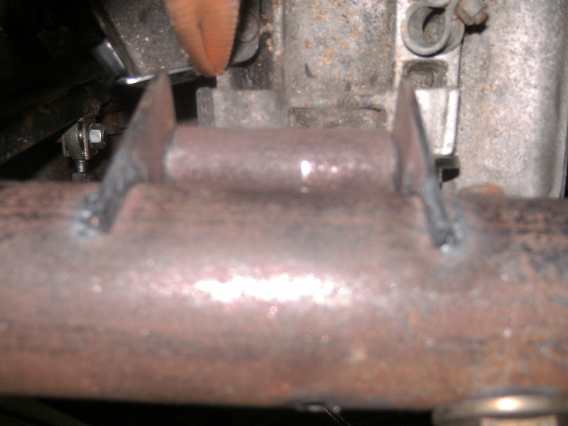
Must make sure the sprung doesn't touch the unsprung
I wanted the Rover fuel pump as to keep things together, for a multitude of reasons.
Ofc you can't get to the tank from the interior... Grrrrr... out with it than
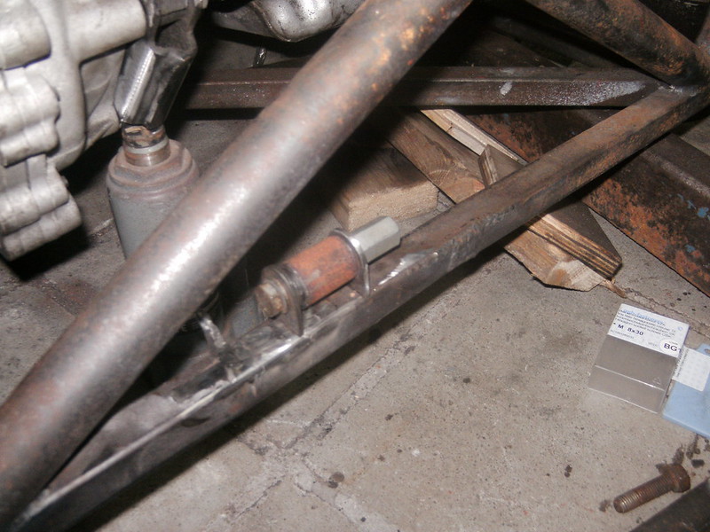
The last mount
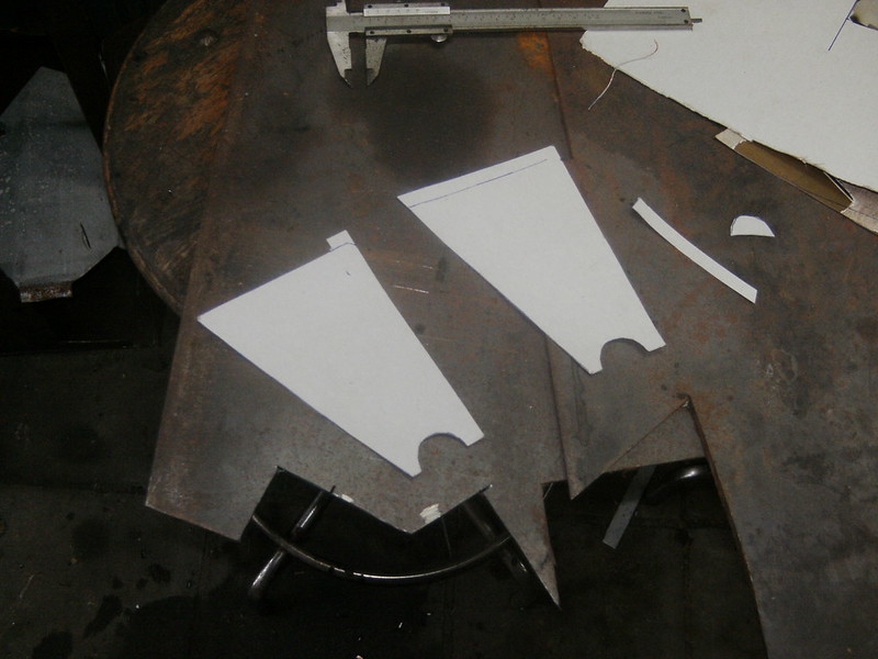
Some CAD
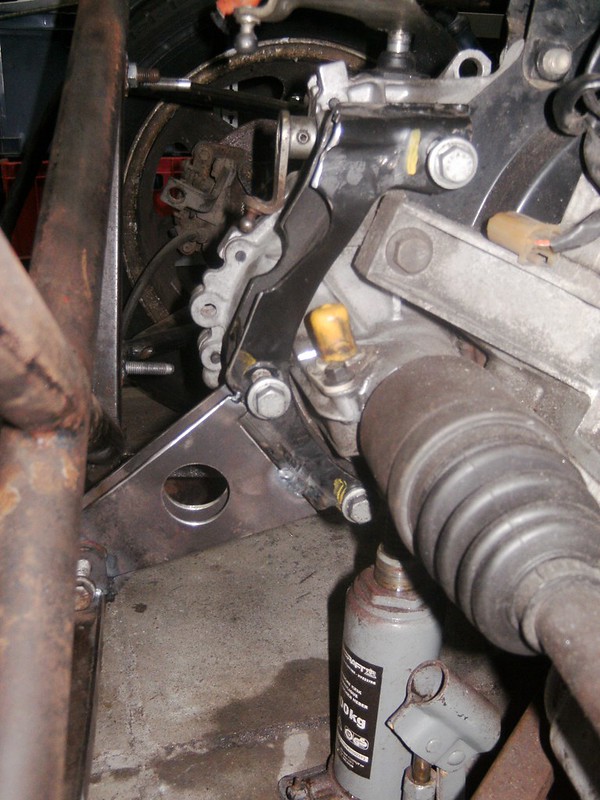
Mocked up
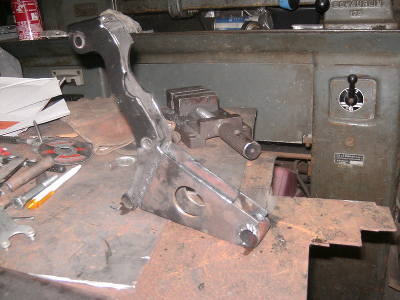
Welded
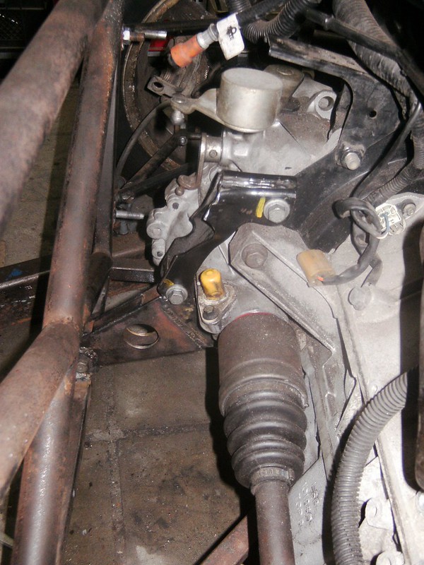
Done...
Now she's going on the ramp again so I can clean up and clear the cave
drt - 25/5/18 at 06:22 PM
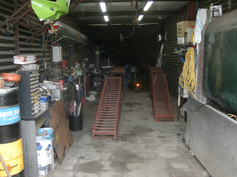
As you can see the cave needed some attention... made use of the car being out to set up the ramps
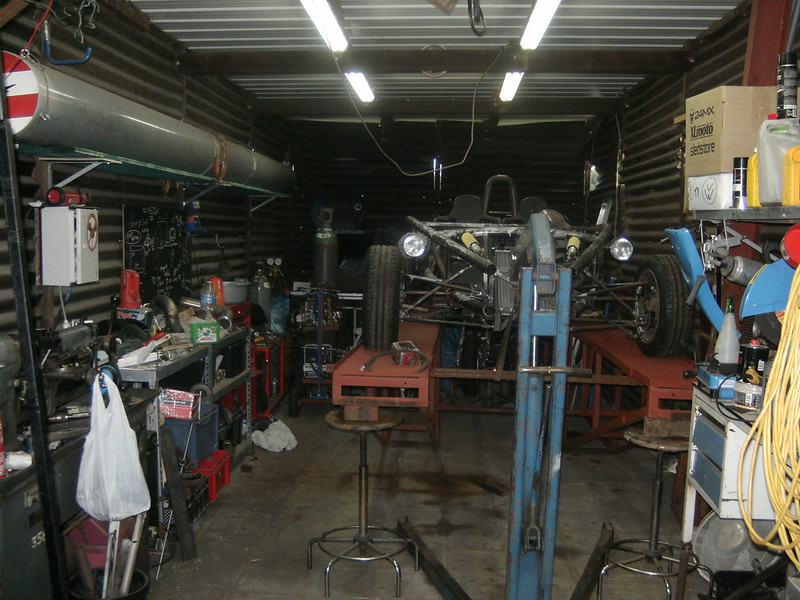
She is on the ramps again... far better to work standing up
Still a mess, although the floor is hoovered.
I'll get you guys an after picture as well.
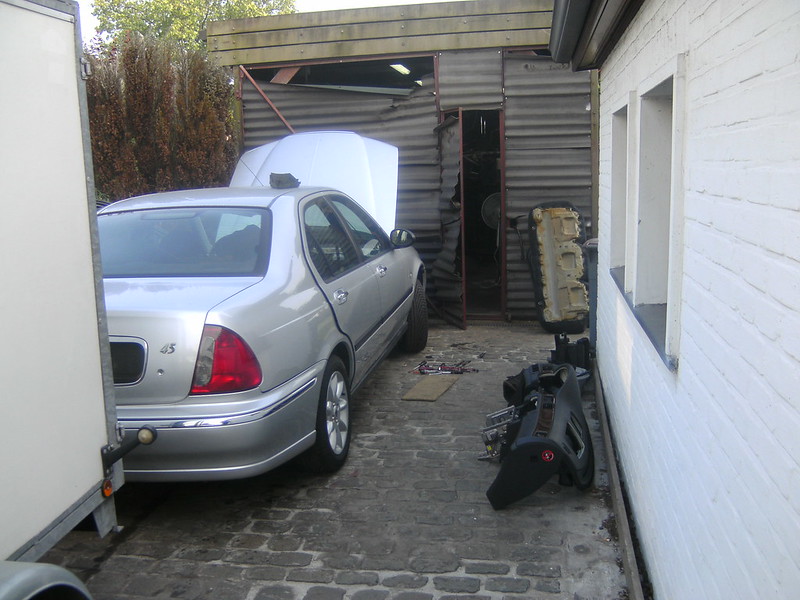
Since it was such a nice day today I thought to strip the harnas from the Rover.. as in not to be cooped up.
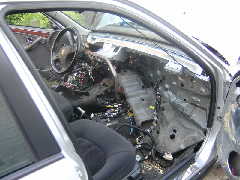
My mistake... what an absolute pain in the ...
Thanks rover for hiding it behind EVERYTHING... trim, heater, pedalbox, you name it, it's out.
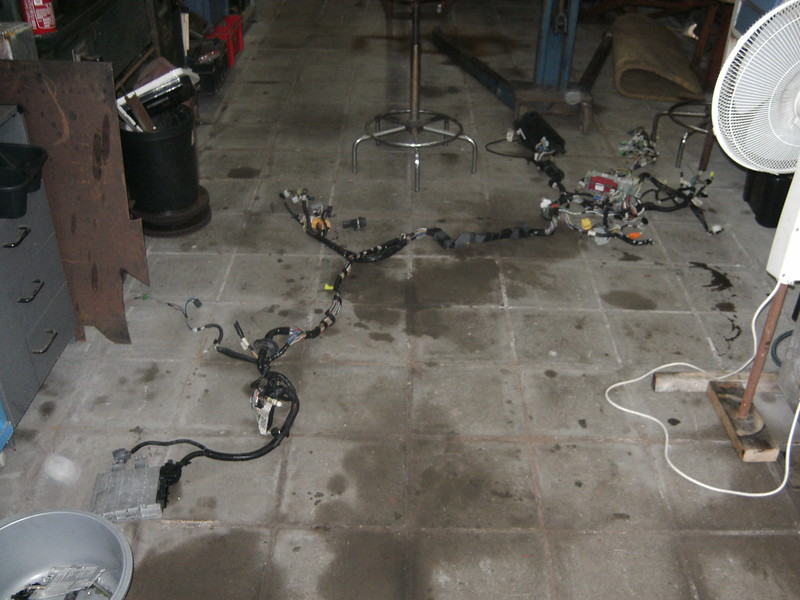
So just a quick bite, upload photo's and on with the jungle of wires...
As I see it, and please correct me, the MEMS just needs the key-fob-detector-thing and power going to it from the interior side of things?
The engine side is a separate connector... so not involved in this discussion.
drt - 12/6/18 at 11:53 PM
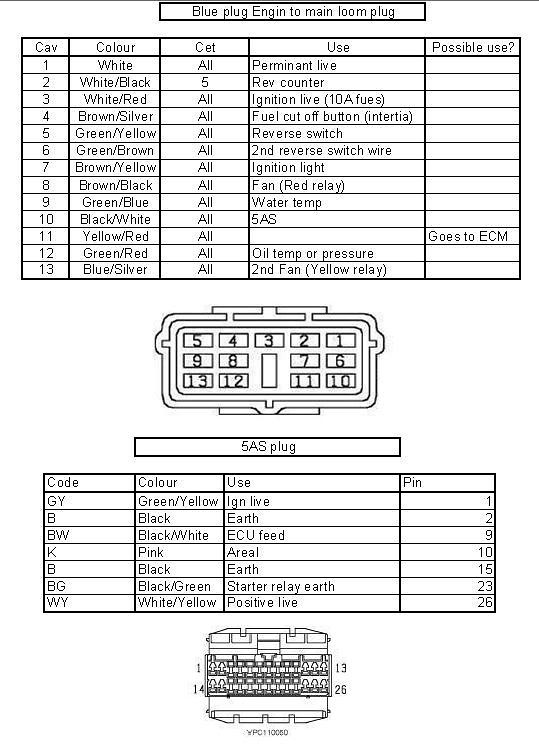
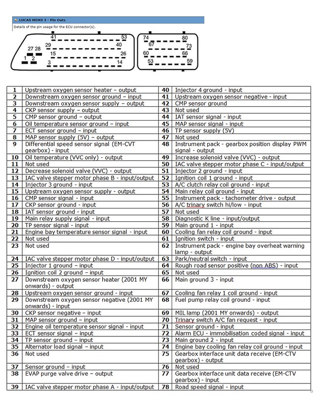
Sooo after going through wires upon wires like a hairdresser trying to separate the interesting ones...
I gave up, searched for the diagrams and came up with these.
5AS
MEMS3 pinout
Soo, got rid of the lot and going to make my own loom... debating sticking the keyfob to the detector to avoid the burden.
But then again, it is an excellent anti-theft device
After giving up on that I ran into some older atom pictures and noted that those didn't have elaborate seat structures.
Given that my seats are cheap-will-do-for-nows and are not self supporting I started playing with the idea of altering the existing set-up.
What used to be...
I got get rid of about 30kg of weight while losing some Newtons/degree... since the emphasis has changed to keeping it light, I went for it.
Thinking I would not change the seat position I replaced the old bottom up design for a hanging one.
But then i realized that I had more room under the seats and could get the COG lower... Since we are talking about 200kg of weight fully laden this is
not to be sniffed at dynamically speaking.
The most radical seat position won some 15cm in max. height and some 10 in COG.
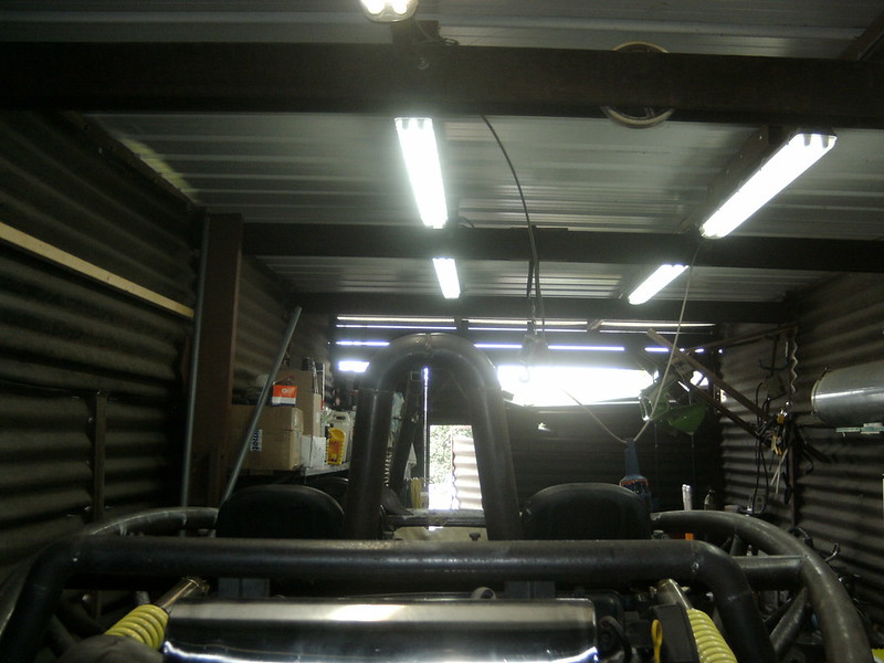
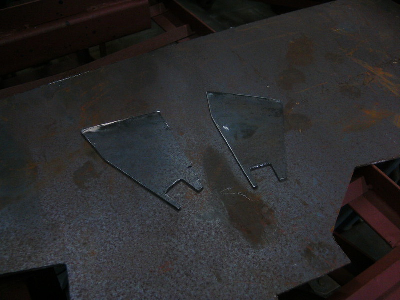
Making brackets again.
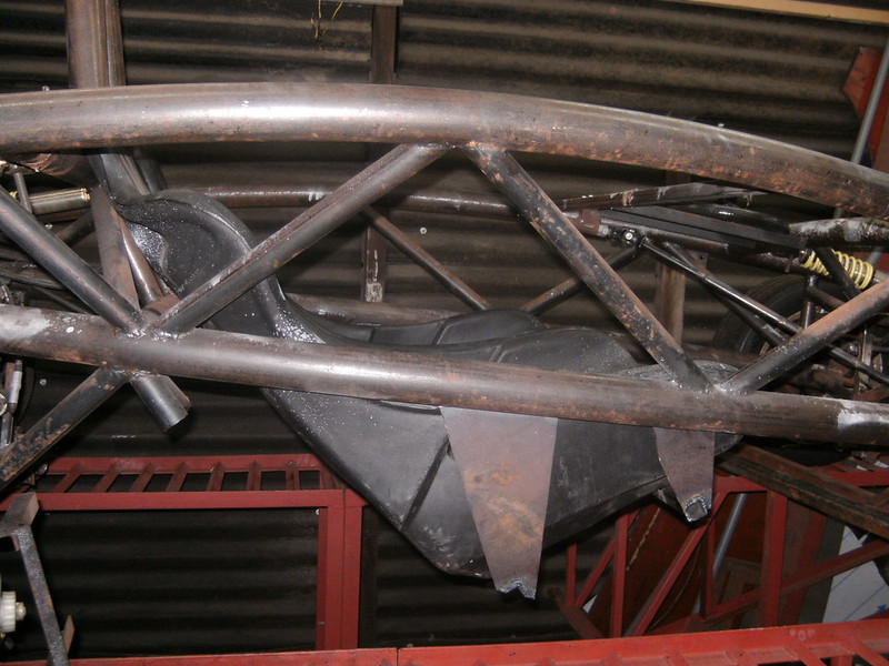
So this is the new position. With this position it is impossible to put weight on the 'hammock' style bodywork. So this is now going to be
lighter, thinner and cheaper to.
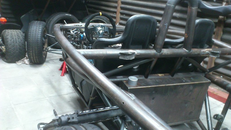
For comparison
For the gear selector I'm thinking of laminating a bulge in the hammock... or going with a DIY electronic shifter.
Also I have been paining myself over the radiators, they are a packaging nightmare.
Since the now live where a lot of other stuff could be neatly stuffed.
Bought these Polo rads cause they were cheap and the locost standard, but actually to big to live in my nose cone.
Been searching.
CAR l x h x d in mm
Micra K11 1.0 380 X 370 X 17
Panda 45pk 1992 0.9 462 x 240 x 35
Panda fire 1994 520 x 250 x 34
Punto 55 1.1 1993 435 x 322 x 23
Deawoo Matiz 0.8 458 X 294 X 16
Fiat Cinquecento 0.7 31pk 312 X 214 X 24
Fiat Cinquecento 0.9 41pk 248 x 465 x 34
VW polo II 1986 1.0 40pk 380 x 322 x 38
VW polo III 1.0 45pk 430 x 322 x 34
Civic V 1.3 75pk 1995 346 x 346 x 24
saxo 390 x 322 x 23
Opel Agila A 1.0 377 x 378 x 34
Subaru justy 2001 1.3 330 x 350 x 16
Panda 1986 583 x 250 x 34
UNO 1.0 1992 312 x 340 x 32
Alto V 1.0 2000 325 x 360 x 18
swift 1.0 2001 408 x 341 x 34
Now the Cinquecento 0.7 one would be excellent, well 2 of them in front one another anyway.
But they are quite rare, even new, 0.9 was way more popular but it's too wide.
95 Civic Might be the best compromise, looked at rover mini's but they are 5 times the price.
Thoughts anyone ?
Next steps... a complete steering system overhaul
drt - 14/6/18 at 12:47 AM
So tonight the steering system
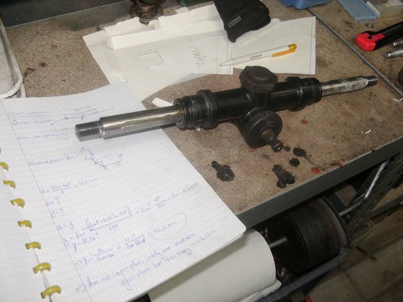
As the geometry changed the location of the steering rack was no longer correct.
And there was the little thingy with the pesky Pauli principle regarding a steering rod and a chassis.
So to keep it simple the steering rods will be in the same plane as the upper wishbone.
This means the inboard pivot point must be on the same point along the X-axis.
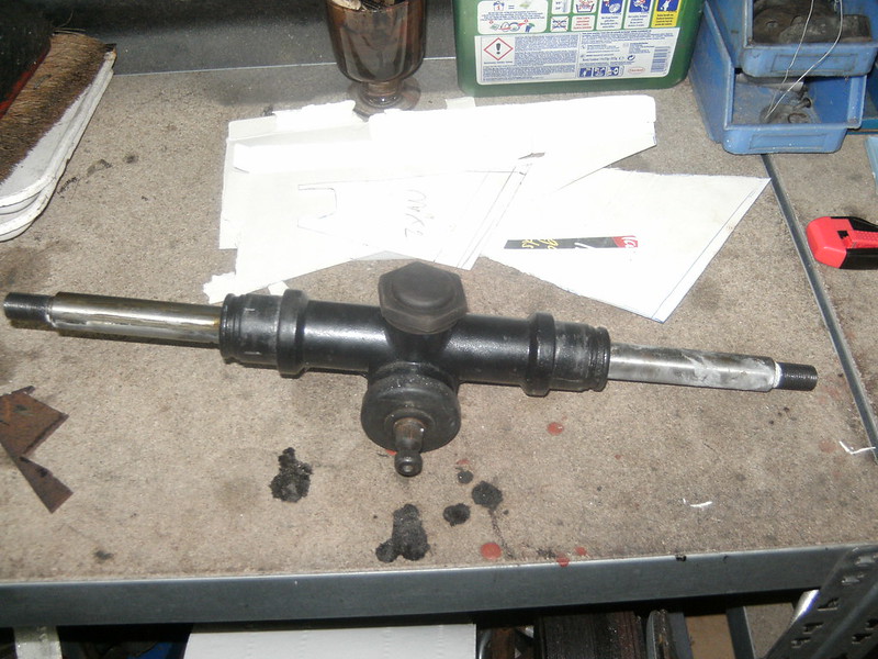
Since the steering rack pivot point combo I was using is about 25mm to wide at the narrowest setting it meant...
Bodging time!
Steering rack without pivot points
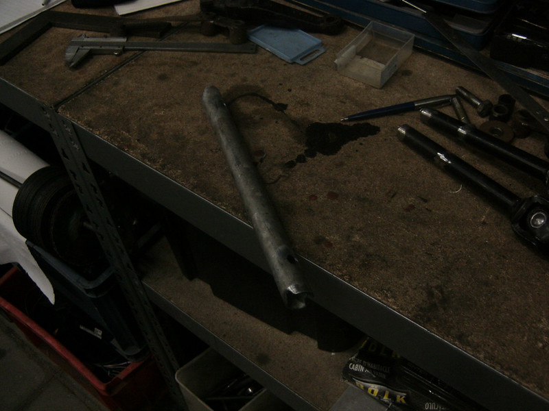
The pictures I took of the process didn't go through for some reason. But is was a simple case of putting it in the lathe,
taking out the dial gauge, swearing for an hour to get it somewhere near concentric along its length,
machining off the threaded ends, boring a hole and tapping it.
Result;
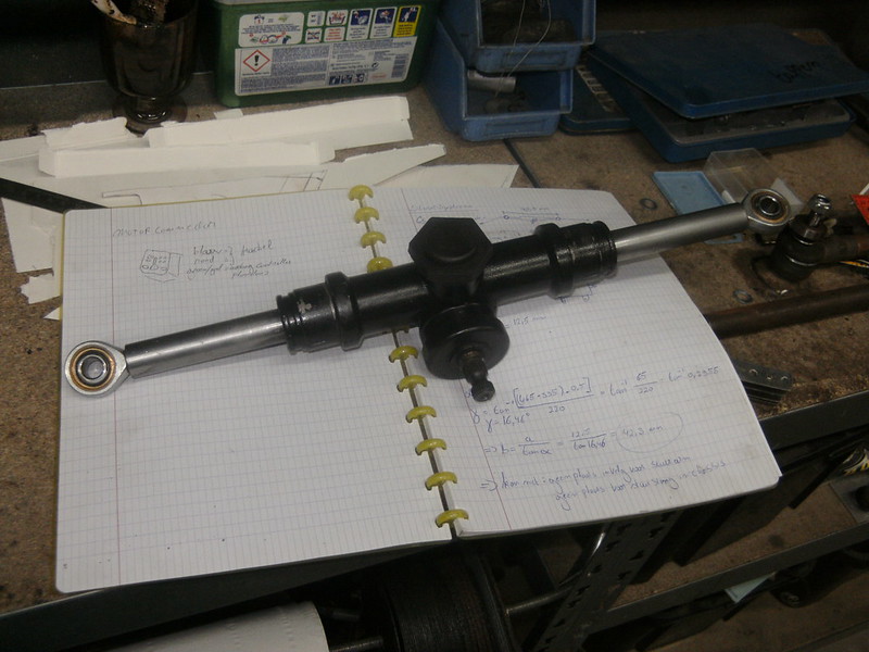
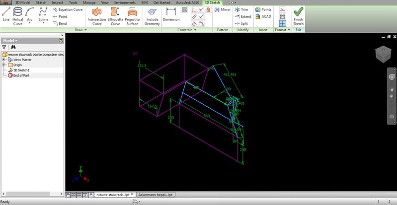
Now I'm gonna run some simulations to see if my assumptions regarding the Ackermann and bumb-steer are still correct.
drt - 15/6/18 at 11:44 PM
few days of careful progress, calculations and simulations.
Trying to get the steering rack in the best position and minimising bump-steer.
So first some very quick and dirty simulations to check the maths and quickly alter the set-up.
This used to be the home of the rack and rad... it's all on its way out.
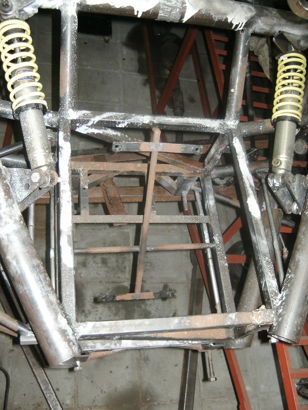
So firstly setting up the rack so it is exactly the width of the top suspension points, done that by putting the bolts through.
Because fabrication tolerances XD
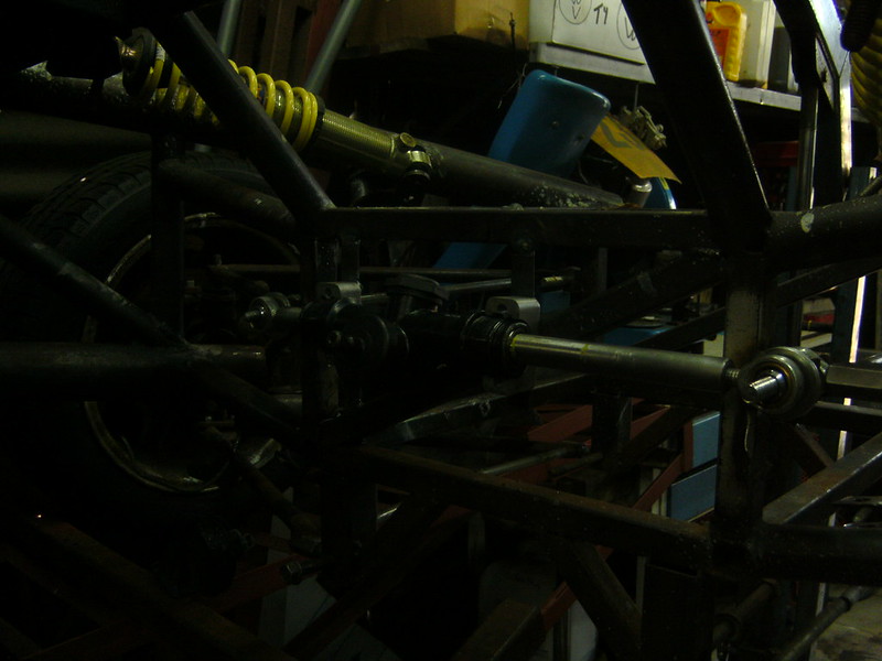
2 little profiles, drilled and installed. Now scribe from the back where it needs to be cut.
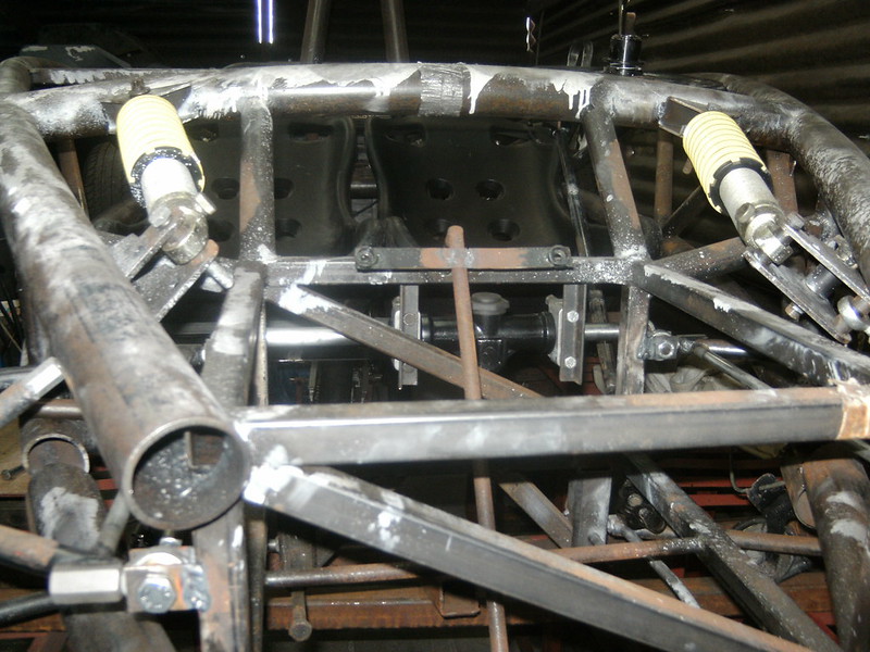
Installed
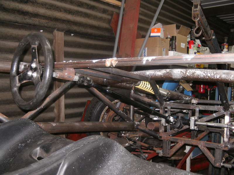
A new steering down tube, with some recesses to increase the weld area and have a mechanical way of transmitting the torque.
So that is operational, kinda low on pedal box space... but we'll pas that bridge in due time
So now to hide my shame
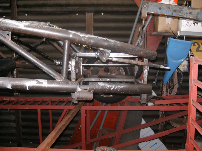
10 minutes of cardboard and 10 minutes of grinding later.
Set the TIG to 11
Had a look at the files from way back when... to establish the steering-arm.
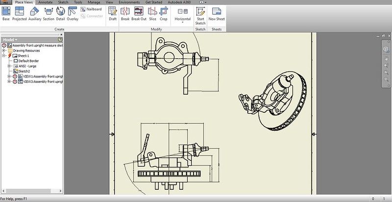
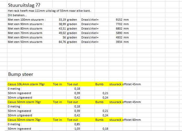
Sorry for the lingo in these notes, I tend to go between a fair few languages. So after establishing the Ackermann angle followed the minimising of
the bump steer and combining that with the space in the rim, I got the lengths of steering arm I could get away with.
This now remains a choice of steering wheel torque vs. turning circle.
drt - 16/6/18 at 09:39 PM
Not a lot today...
watching the start of the 24h... and listening to radiolemans in the shed does that to a man.
Hiding the shame on the other side
And pulled this out of a the heap...
Mini 1300 high volume rad.
I'm thinking of using it, but I recon it will be on the small side.
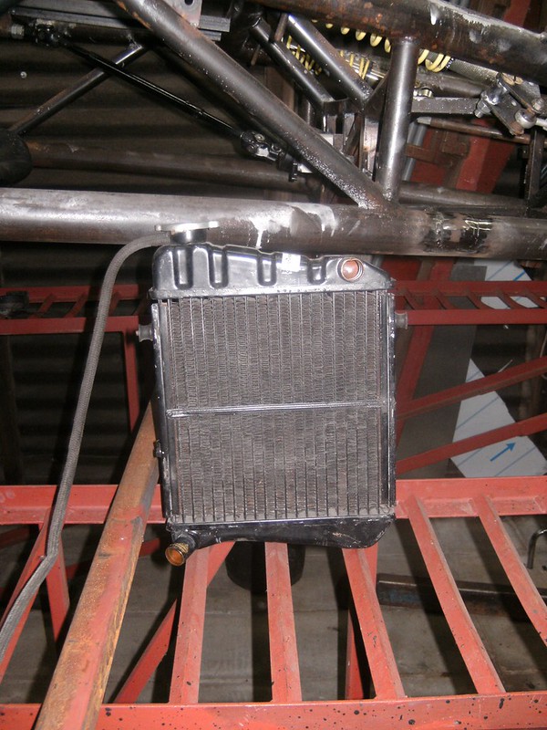
opinions ?
drt - 20/6/18 at 09:30 PM
Continuing with the steering arms.
Machined some parts.
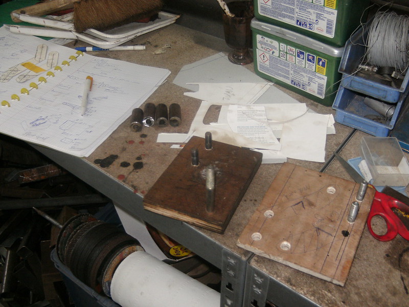
Fixed to a little weld mold. Need some more parts before I can finish them.
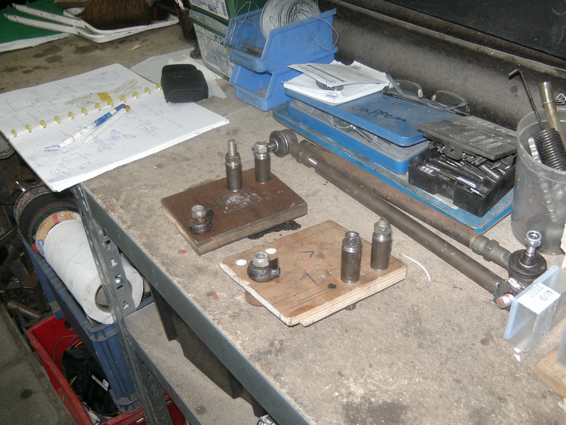
Last new pick up points
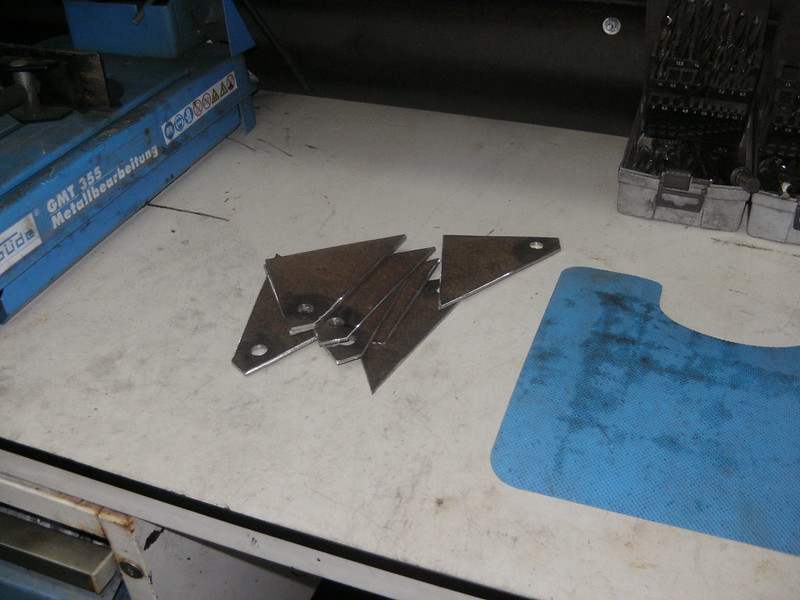
Out with the old
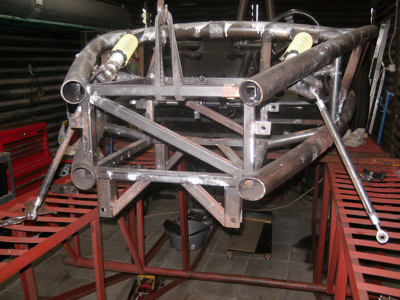
In with the new
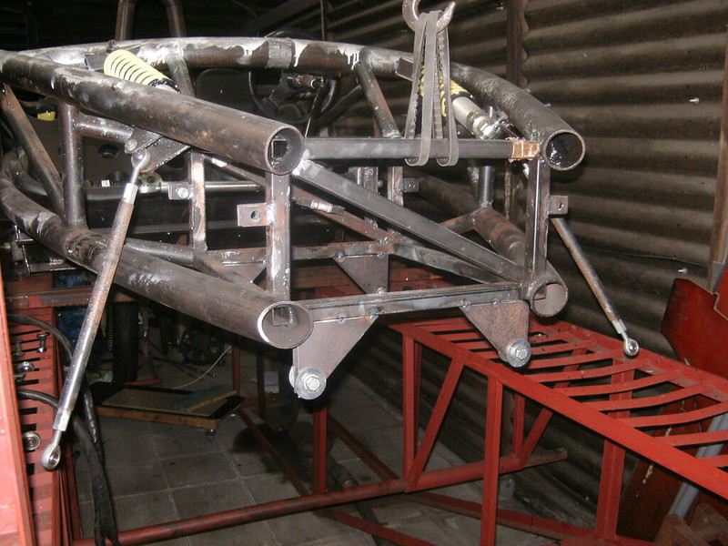
Added sides and done.
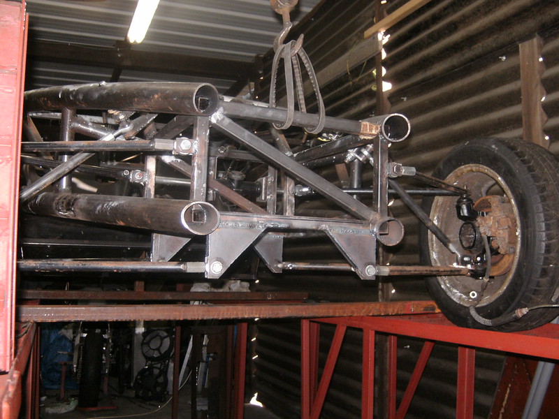
AdamR20 - 21/6/18 at 08:38 AM
You're nuts, I love it!
Rad looks a bit small to me too. Will a Polo one fit? Works fine on my 1800 Zetec with 185bhp.
drt - 21/6/18 at 09:21 AM
Thanks... I think XD
Well, I've been down the polo rad road (see above) and it was a packaging+flow nightmare.
The car either needs one just the right size so it fits the front
see...
Or in sidepods like the oil coolers of the 500.
Thanks for the reply, I was starting to think people lost hope
AdamR20 - 21/6/18 at 09:25 AM
Give it a try with what you have, with good ducting and low % of antifreeze it may work. You could also stick an extra bit of cooling in afterwards
(such as a heater matrix or small motorbike rad in a side pod) if needed.
drt - 21/6/18 at 09:35 AM
Using the rover K I'm a bit nervous on just trying.
But simulating a radiator is a real pita... there are so many unknowns 
But your heater matrix idea sounds elegant. Small enough to fit in a sidepod and plenty available.
I dismissed matrices because I thought they are high resistance for coolant and optimised for slow air flow, no ?
AdamR20 - 21/6/18 at 09:38 AM
I'm not certain - but - to me that sounds like a beneficial condition perhaps. If the water spends more time in the radiator it will get cooled
down more I suppose, if it flows through fast it won't have time to cool down!
Edit: Maybe it could be 'branched' off the main coolant hoses a bit like an actual heater matrix to prevent poor flow through the main
cooling system, then have a fan hooked up if there's poor air flow. When I've taken 'normal' cars on track having the heater on
full blast does seem to make a different to water temp.
[Edited on 21/6/18 by AdamR20]
drt - 21/6/18 at 10:25 AM
The slower the flow of a heat exchanger, the nearer the temp of the fluid can reach the temp of the air.
But the less efficient it is, it's a case of what you need.
Like a household radiator is huge and slow... so it can give of almost all the heat in the fluid (limited by convection and a bit of radiation).
But a car radiator is optimised for high flow rates of both the coolant as well as the air, so it can efficiently lower the coolant temp from EG. 100
degr C to 80C in a small period of time.
Because the flow rates are very high in the end the total amount of energy expelled is much higher than the slow one, this is also because the heat
exchange rate is not linear.
Q = + (m1)(Cp1)(T1in - T1out)
Q = + (m2)(Cp2)(T2in - T2out)
DTlm = [(T1in - T2out) - (T1out - T2in)]/ln[(T1in - T2out)/(T1out - T2in)]
Q = U A DTlm
It's always a case of the more you know, the less you know 
But nonetheless, still going to try 
drt - 21/6/18 at 09:19 PM
DAMN...
Pushed my luck on this one.
The weld mold was insufficient for keeping the parts in place.
Didn't help that the tolerances for the connection with the upright is about 0.5mm
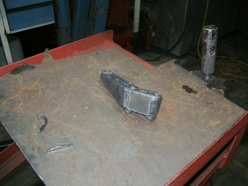
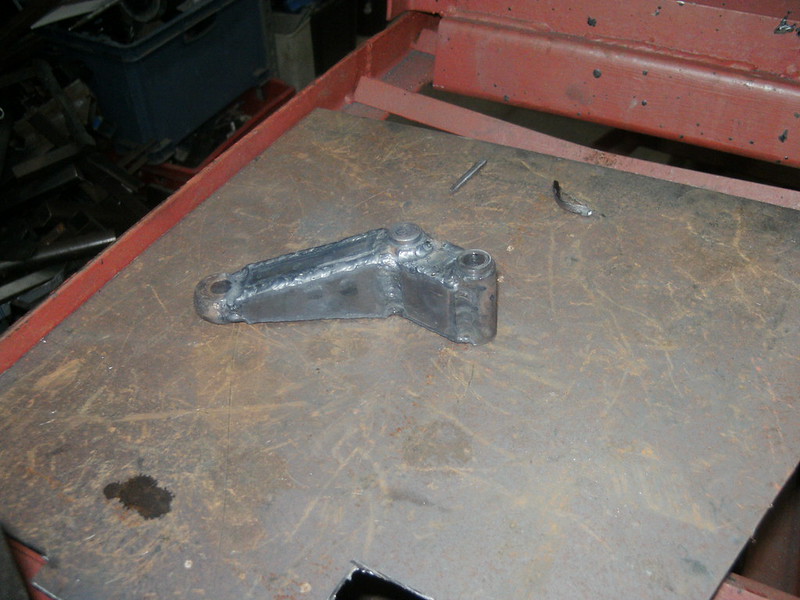
So now I'm going to have to get them milled... a bit of a bugger since it's going to be costly judging by the details.
Ofc everything is relative, but atm the whole project has only cost me around 1200 eur.
Any machinist out there ?
woodsy144 - 20/1/19 at 10:08 AM
Hello,
I am interested in your steering rack.
May I ask, where did you source it from??
Make, model, donor, etc??
Thanks
Tim
drt - 12/4/19 at 11:39 PM
So after not even being in the same country as the project for a long long time, where back
In last episode, a dog's breakfast steering arm... that didnt work.
now she has 2 machined ones... only 0,1 degree bumpsteer at max deflection and very nice ackermann.
But, in a weird twist of faith, again there is some chassis in the way.
So out with the grinder
[img] 216
(2) by paris r, on Flickr[/img]
Some newspaper aided design.
[img] 217
(1) by paris r, on Flickr[/img]
Grinded
[img] 217
(2) by paris r, on Flickr[/img]
Installed
[img] 217
(4) by paris r, on Flickr[/img]
then invented some bracketry to put the alternator somewhere where Rover didn't think off...amateurs
[img]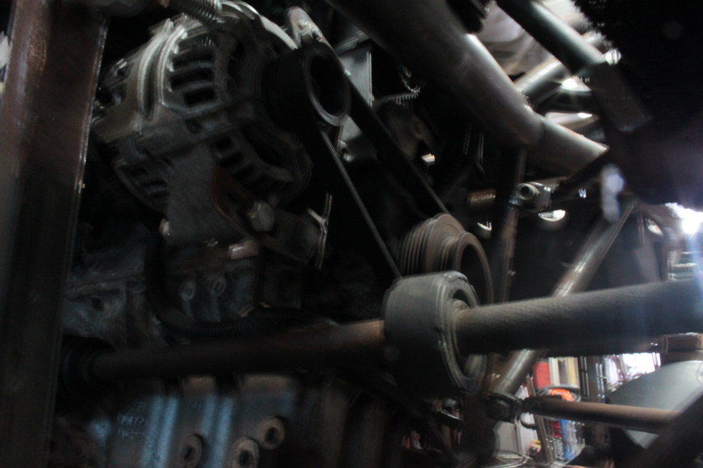 216
(5) by paris r, on Flickr[/img]
Exhaust is being rerouted atm, pics tomorrow. Gave me a headache for the longest time, as NA-engines.. you know the drill.
Brake lines are made and ready to go in.
I'm hoping to finish the bl**dy thing now...
wish me luck
drt - 17/4/19 at 07:55 PM
Original flanges didn't fit, so made some to work with the OEM gasket.

so that makes the front part...

And then... watching the grand tour Mongolia, I was laughing that the mistaken steering rack position must have been scripted...
Until I found out that I did so too months back... pays to sometimes sit in it and make noises. So new steering rack position requires new
mounts...

Spacers
so all together...

Positioned correctly,

Installed

lovely jubbly

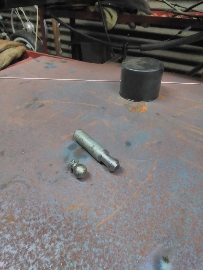
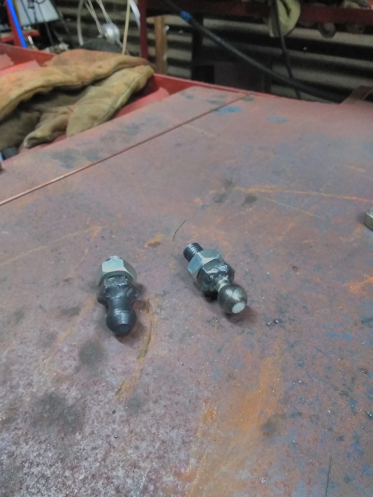
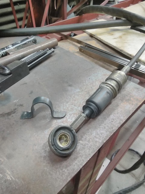
So on with the gear shift... found out the MG F cables do not fit the Rover 45 gearbox ball joints... what a joke! It's the same friggen
gearbox.
Looked to get some locally, no dice. Looked on the confuser... 15 QUID !!! for 1. So I set out turning one

Horrible job, but it works... spare the phallus jokes
 [url=https://flic.kr/p/2fz2ade]
So now onwards to instal the gearshift.
drt - 24/4/19 at 11:05 PM
This post I scaled down the resolution of the embedded pics... because the big ones are hard to get an overview IMHO.
Please let me know if you want them big again or this is better. Thanks
So since I had some assistance I put it to work on the battery tray

Because thatīs going here, for weight distri

Making it stiffer with some flanges

tricky to weld as itīs less than a mm sheet

now to combine: added support for the battery + a, laterally stiff, jacking point + support for the nose cone

All done;

bending a try-out for a selector cable bracket

Lower selector

And the upper one

drt - 5/5/19 at 01:04 AM
this week...
Gear selector deja vue

and some more 'deja'

Lathed a bushing, since I had to elongate the OEM shifter cable... the system is done some more pics next time

On to a hot potato... with cooling
This has been a point of debate over the last few weeks... months even. Where to put the rad.
History has told us that putting them in the nose either requires custom rads = don't have the funds for that and K's like a short cooling
route
Or a huge waste of space (by being in between the dampers) = want to use it for electrics etc
Pontoons = needs either custom or motorbike rads and require the build of a model+mold+product
So I preferred it in front of the engine sucking air from underneath ( apparently the new atom has such a set-up) = need a new fuel tank and the flow
underneath is probs not laminar so quite a huge duct would be sticking out underneath... and trial fits pointed out that there is little room for a
fan
Exhaust ? I'm wrapping it and using the OEM heat shield...
Another solution would be scooby intercooler style, using the airbox to duct air to it... CFD made me nervous about the outflow of air between de rad
and the engine.
Even having the rads parallel to the car and ducting air in (Honda VTR style) was considered.
In the end I came to a compromise having the rad at shoulder height between the occupants, aided by air ducted by the air box.
This way there is good flow, room for fan+ducting, a short cooling circuit and no need for extra bodywork.

So, OEM rad mount rubbers in need of a home

Just put a sock'n'et


Polo rad mounting not readily compatible with those rubbers

And now it is
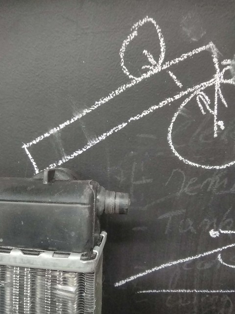
Upper mount, captive nut plate

Some pieces of angle grinded steel

Holed and bent (attempt 99999)

Factory ...XD

drt - 9/5/19 at 10:37 PM
Out with the selector for some final tweeking... titled: tweeking_9.5_finalversion_7... if you catch my drift
Just to prove that many parts go through many many iterations off camera... here is a rad shroud i spent several hours on and than binned

Just realised I have not taken a pic of how the rad shroud ended up 
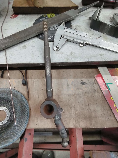
This is how the selector ended up, it's light and stiff this way... and fits the seats.

Than hours of trial fitting the paddles to make m fit 'just so' ... so here is the bracket

Foot rest

Fitted

As by magic... here is the master cilinder


drt - 10/5/19 at 01:07 PM
As promised...
a dirty deed, done dirt cheap
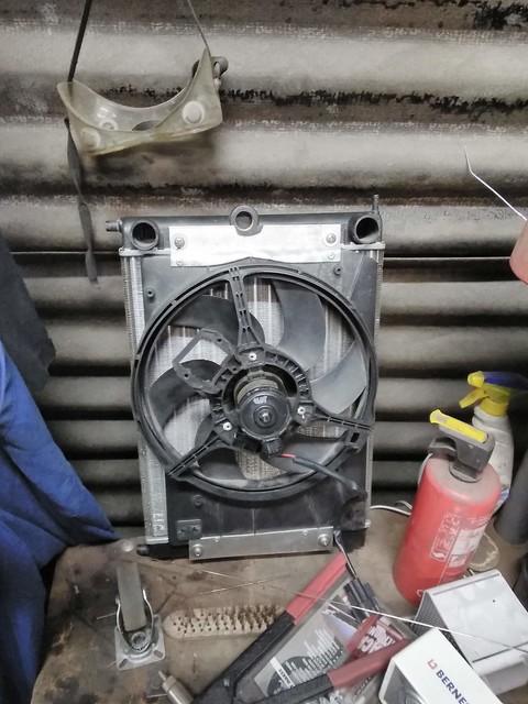
I've posted a question in 'donor parts'... any help greatly appreciated
drt - 14/5/19 at 11:01 PM
For simplicity I decided to use the rover master+slave clutch cylinder this called for a remake of the pedal box

Stiffer, lighter and more elegant

So something came in the post today...

So I was ...wrapping to the beat...

In situe

Some brackets and a heat shield later I'm confident that this area (and thus the rad and fuel tank) will stay cool

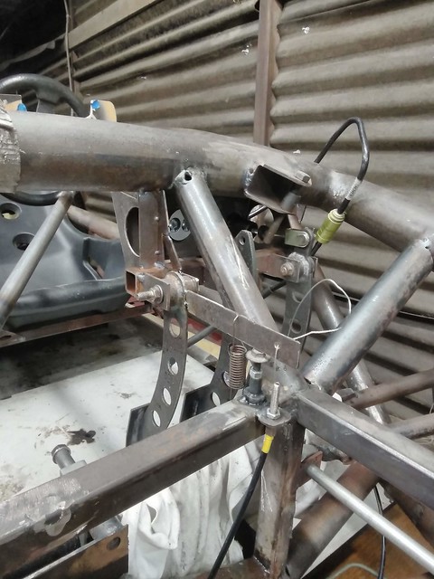
Everybody had me doing the run around, as no OEM throttle cables are long enough. In the end I bought the correct length outer cable from the bicycle
repair shop who has the stuff on a 1000m spindle and bought some steel wire in the DIY shop.

I had always planned on running the cable like this and was very happy with the snazzy bracket for a while

Then it came to my attention that the travel of the rover throttle body is quite long and so the throw on the accelerator pedal was too much
(can't go higher to get less throw as it will stick out over the bodywork).
So I elongated and rotated the lever 90 degrees and came out to this compromise... a bit sad that it isn't snazzy and that the cable operation
now lives where I planned my electrics and shopping compartment...
drt - 20/5/19 at 10:24 PM
This week...
I'm still investigating how to connect my master and slave clutch cylinders... I've posted the question in the donor parts section.
ATM the prefered solution is to get some 4 or 5mm flexible hydraulic tube (6mm fitting) and use jubilee clips... some hydraulics guy told me that
should do.

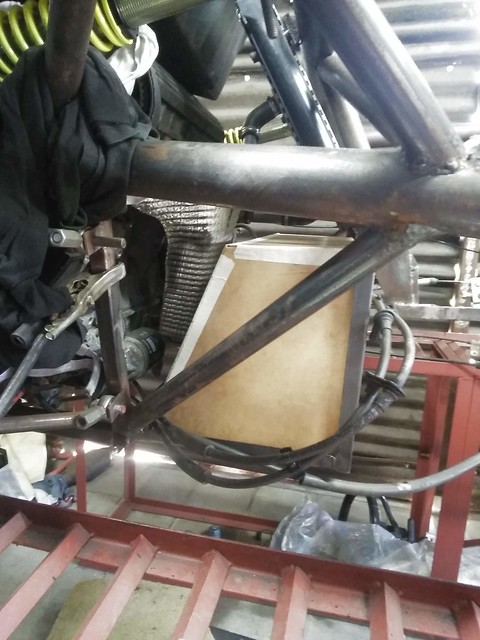
Then, the MK2 fuel tank is not going to fit the newest alterations.. so we'll need an mk3. Made a model this time because I want it the 3rd time
to be the charm.

A whole day of making a removable tray later...

Even with the hear shield, the exhaust wrap I feel it's to close for comfort. So a few versions later we have 42l of fuel capacity and 20mm of
clearance between the heat shield and tank. For that little extra something I have some space age non conductive stick-on pads, just for the closest
bits.
Currently debating which water tank to use from my years and years of collecting, along with where to put it.
This debate also includes whether or not to use the OEM airbox and how in conjunction with the air scoop.
Ariel has an interesting way of doing it... but it means a lot of fabricating an loss of plenum.

had the gf over (believe it or not) and decided to do something nice together, my man logic went: she enjoys sewing =so cloth = carbon is woven = it
must be a cloth = QED she will enjoy some lay-up...
...God, was I wrong
But it turned out nice ! And the Dash got an outing after years in the box.

And the last job today was to fabricate harness mounts and fit them

scudderfish - 21/5/19 at 05:28 PM
Keep the posts & pictures coming 
drt - 26/5/19 at 10:43 PM
Thanks scudderfish, means a lot to have some encouragement!
This week,
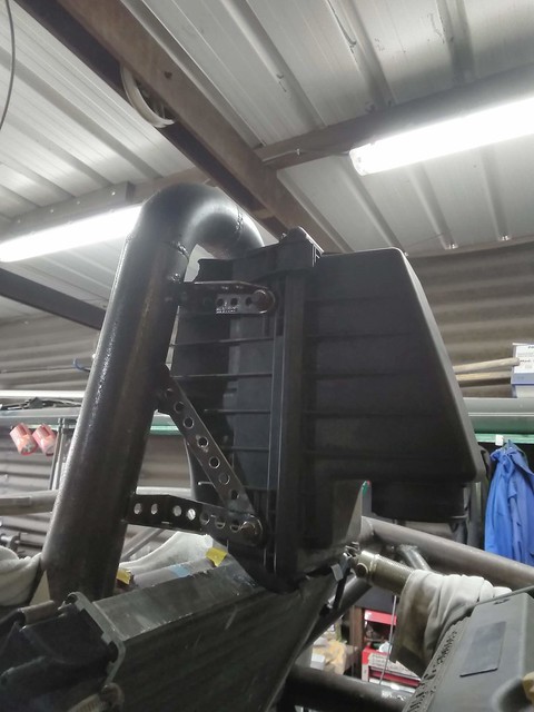
I started with the airbox... this is the OEM rover airbox

Hack sawed it to bits...

So it fits here... so I'm going to use the air scoop (CFRP) just as a cover. A bit disappointing as I was hoping for E46 m3 CSL resonance noises,
but that probabaly would have been a cacophony. This way I can use the OEM paper air filter, which is cheap, cheerful and better than a chinesium pod
filter

So it's a bit of a bodge right now but I'll have to plastic weld or glue some bits too it... and the water drain

After a whole day of fitting, bending, grinding, drilling
Then, the water tank had to be placed at a point higher then the head/rad/... somewhere where it wouldn't intervene with the air flow coming from
the rad and somewhere where I could block the acces to the cap (100% sure otherwise someone would nick it for giggles)

A few attempts and generations of brackets later...

The end is nigh

So I found a solution to my clutch line problem, this is some thermoplastic hydraulic line... it should be able to cope with DOT4 and my only worry is
that it is only rated for 20bar of pressure. The up side is that by heating the line and the fitting I could just push it on.
But It came to me that the slave doesnt have a bleed nipple ????!!!! How do they do that ???? 


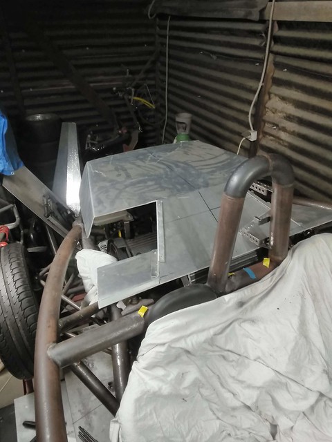
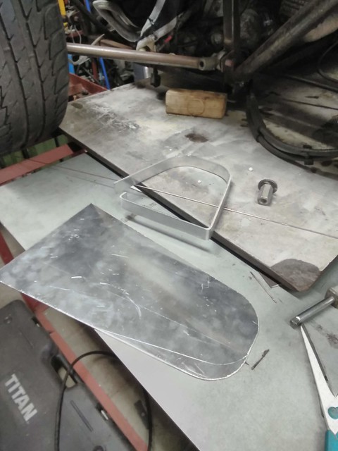
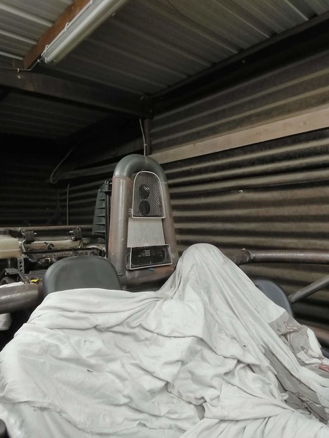
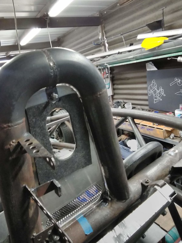
Now for the air intake, cut out the space onder the roll bar in alli and then hand bend some strip into the right shape
Welded

Did the same for a lower intake (not to block the rad) and cut some holes.
The mesh is what I had around, probably going to change it for a better pattern.
And I still have to decide if I'll glue this to the air box or screw it to the hoop.
drt - 30/5/19 at 11:54 PM
Update... I'll be looking for opinions on the fuel tank later in this post, so please, fingers on the buttons.
Starting where we left of. The airbox.
It needed a bit more hacksawing.

So now the front is more flat it received a nice multiple bent piece of alli. Glued and riveted, with the glue sealing off the OEM airbox.

Fitted to copy the hole and measure the width of the gap


So a nice hole in the box.

Then some double sided tape and 5mm PVC foam
Voila, painted and done

Then, the cooling system.
The K-series asks for some hot water from the engine to always be circulating round bypassing the rad so the thermostat would open.
Not the best design, but it needs this to work.
So had to make a conduit for this, and block off the return from the heater.

I tried for a whole day to nicely bend up the conduit by heating it and filling it with sand.
Needles to say I wasn't successful. For the time being it's going to be 90degree bends then. A bit of a sin... I know 

So here it is with the water tank fitted up too

Then, the fuel tank.

So, here are my baffles. I want your opinions on the design of these. I wanted the fuel to level out between the 3 chambers quickly while refuelling
while still combating sloshing and then have only minor openings to try and keep the fuel near the pick up point.
Around the pick up there is an extra wall so fuel can come into that area relatively easy but won't leave.

It moved a bit under welding...
The baffles are quite clear now, note that I sunk the filler neck 1cm into the tank so the fuel can expand over a 20 degree delta T (I see this as a
worst case)

And there she is (not yet permanently welded) , I forgot to take a picture of the pick up points, I'll do that tomorrow.
Meanwhile, do people use the nylon sifter from the OEM fuel pump units at the end of the pick ups ? Or just leave it open ?
I'm asking because you can't use a fuel filter before the pump I've heard.

The another request: Where can I obtain 70mm I/D hose that is flexible enough to connect the throttle body to the airbox ? (and doesn't collapse
under 0 bar).

Latest job was creating the fuel pump bracket and finding a place for it.
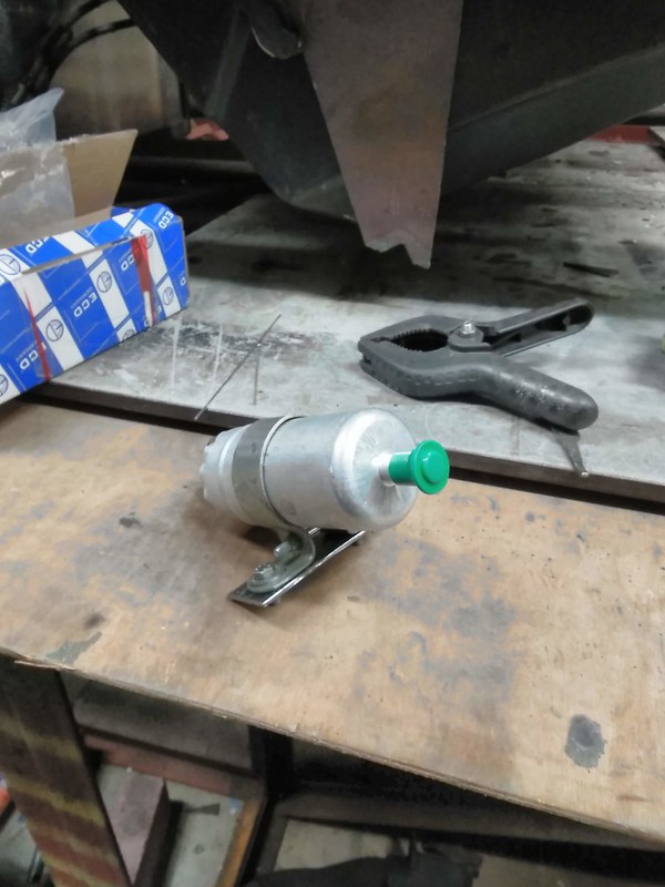
drt - 1/6/19 at 11:35 PM
on tonight's special...
Crushing disappointing as no-one gave his 2 cents...
And more bodging
Without feedback I ploughed on, so this is the baffled tank with:
*A return in the foreground
*A pick up (without mesh, cause I was nervous that over time it might come undone) near the apex of the triangular slush guard
*A tube for the idiot light (reserve indicator) thermistor
*Filler neck (far away)
*Breather (near filler neck)
Welded on top and bottom to fight vibrations

Welding side plates
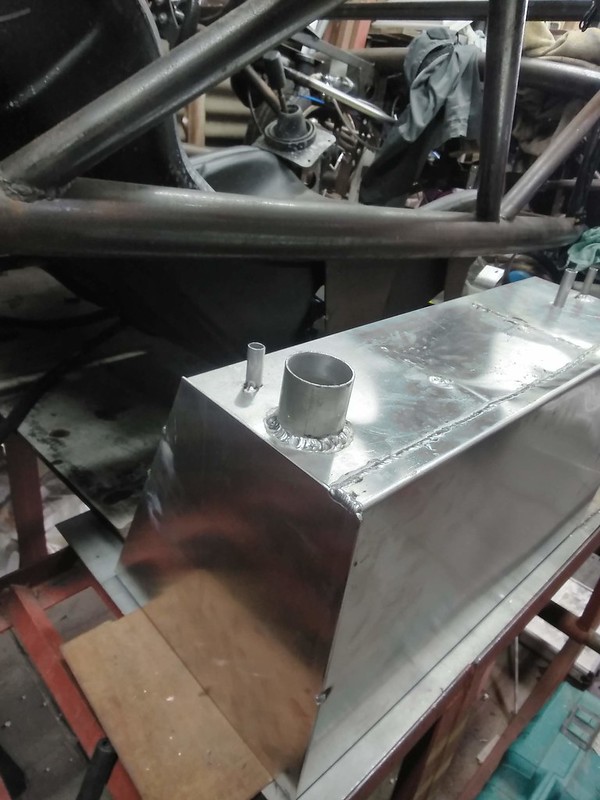
Welded up and pressure testing to 2 atmospheres,
man, alli is really a first time right process. Cause to fix a pinhole just welding over it didn't fix it for me... So grinding it back, cleaning
and re-weld 2-3 cm

So a whole day and night filled up and pressurised later.. no leaks

Double sided tape and foam


Bending the straps
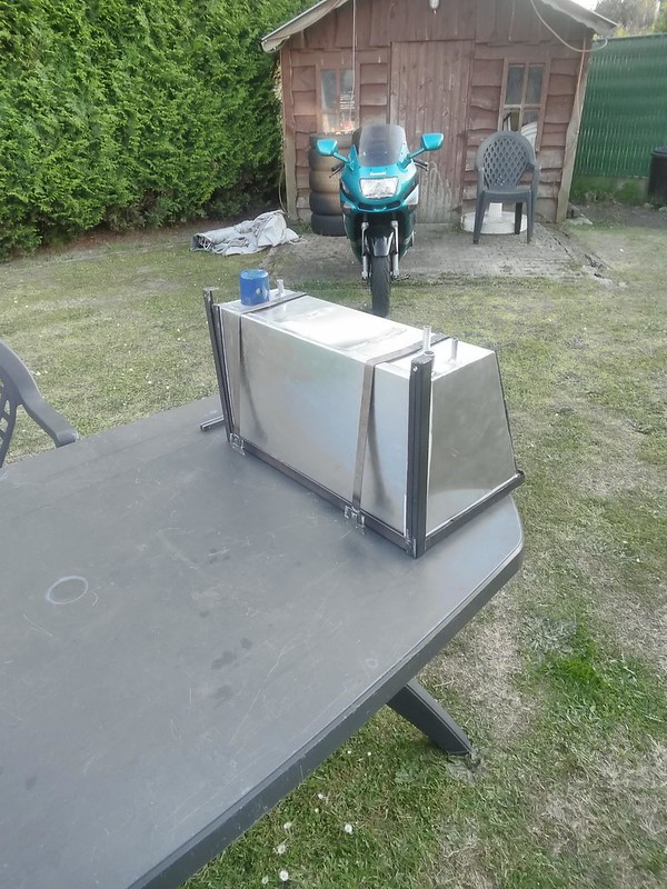
1mm steel work

Foam backed, studs welded and done up

perksy - 2/6/19 at 09:27 AM
Enjoying reading this and the photos are a good size now as it makes it all easier to read and see what you are doing 
miskit - 3/6/19 at 03:16 PM
Looks amazing - thanks for taking the time to write upm - like the photos much better.
Also don't worry if people don't always chime in - they are still reading and enjoying! 
dan8400 - 4/6/19 at 06:23 PM
This is really coming together now. Some lovely fabrication work.
Well done. Keep it up
Thanks
Dan
drt - 4/6/19 at 10:36 PM
Thanks for the kind words,
I welcome any comments you guys would have. Since I am not afraid of redoing something and together we know more then apart.
Especially on this forum where the knowledge base is staggering :p
This time... something what every se7en owner will envy...
A nice roomy box...
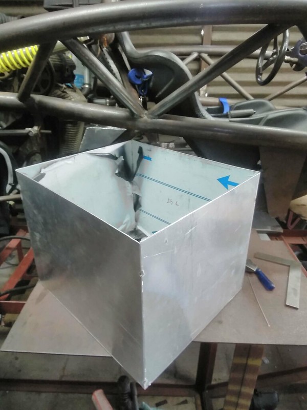
That needs a tight squeeze...

Think I'll call it a boot, mind also the members that where added at the front to stiffen up the protrusion near the box.
Seriously, I measured the frequency off the battery tray/nosecone bracket structure and found that it wasn't stiff enough.
well, now it is

Then I had to find a place for the gas cap (rover filler neck)... since it's not lockable it had to live under the -locked- bonnet.
I prefer it on the right side as that is the curb side over here.
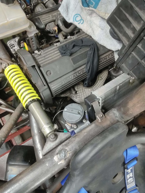
For the ignition I'm using the Rover barrel (with the steering lock bit hacked off) since it's more decent than the aftermarket ones and it
fits the RFID receiver unit. Most barrels dislike water and the RFID doesn't for sure. Meaning that if the barrel had to be in reach when fully
strapped in there weren't many locations suitable. Also the key fob had to be out of reach of my knees to avoid me getting aggravated.
Conclusion was to put it under the knee-shelf thingy but in the middle.
So starting off, like usual, with a perfectly good bit of metal... to then grind and drill it to oblivion.

And there you go, you might think it's a big lump of unnecessary weight to just hold the barrel. You'd be right but I'm planning of
attaching the relays, breakers etc there too, making use of that bit of structure.
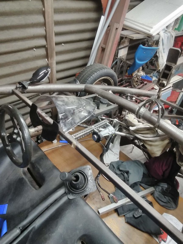
So to allow for the new rad position the mold for the bonnet needed to be altered.
I chose to just lengthen the lip 60mm as this would make the front sit higher and the back end move backwards a bit... aesthetically it's better
(I was surprised too). That lip would have cut outs in the CFRP item to allow air to flow into the rad.

After days of alli welding I was finally getting proficient again, so decided to add the stiffeners to the mold as it has been on the to-do list for a
long time but as the sheet is thin and alli has a penchant to warp it daunted me for the longest time.
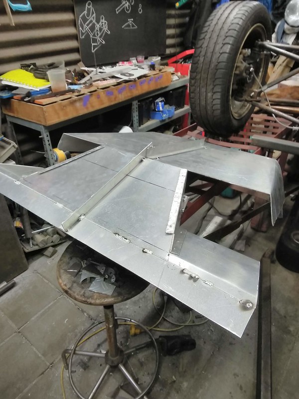
Lastly I started making weld-on-cable-tie-anchor-points for the rooting of cables.

A real labour of patience ...

Theshed - 5/6/19 at 09:27 AM
A slightly easier solution to cable ties is to bond on these things - that is what is used in many race cars
https://www.newark.com/thomas-betts/tc-105/cable-tie-mtg-base-aluminum-25/dp/12C2341
drt - 5/6/19 at 11:15 AM
You beauty!
Promptly ordered
drt - 11/6/19 at 03:55 PM
Not a lot this week
some captive nut plates for the cfrp underbody.
MIGed these as with the TIG I am to prone to melting the threads.
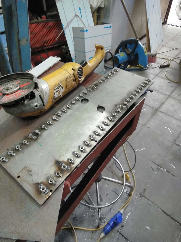
Cut and debured

Tried to fit these nut plates by using the mold... I wasn't successful, so I'll have to invent something when the product is made.

In the mean time... I had a hover car
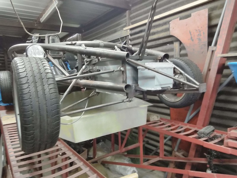
Most of my friggen time went to electrics, buying fuel and some coolant lines/
I must say the RAVE CD's are less then helpfull
and for some reason all the pinouts I can find are not relevant to mine
I'm posting it as a separate question in 'electrics'... I'm very happy for any help
drt - 26/6/19 at 05:37 PM
It has been a while, srr.
Lots on the plate.
Some interviews on the horizon and now doing a interim job just to fund this XD
So since last time... I put her on her wheels and cleaned the hell out of the shed
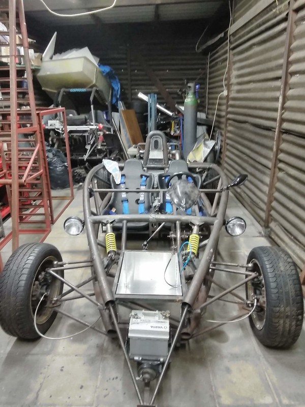
Since the electrics where being tried out preliminary, I wanted to start it.
To not let the pump turn dry I used the brake bleeder to get petrol in the system.
Good news, the whole system works and doesn't leak.
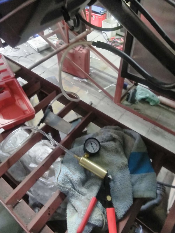
So, the observant might have spotted that I was using the lights at a 90 degree angle...I tried rotating the mirrors for it to comply... no dice.
Therefor experimenting with a new position, where I planned the indicators
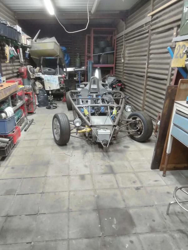
Air intake... needed some ''gasket''

Like this

And then a bit of a bodge. Turns out this material can take a partial vacuum, is bendy, cheap and easy to get hold of XD

And then the first wave of new bolts

drt - 19/4/20 at 10:47 PM
The show must go on...
Since the last upload, a novel-grade series of events has taken place.
the gist of it ?
Father had found a way to leverage all of his outstanding debts with the property.
After a fire-sale of most of my tools I just managed to outrun the bailiffs.
To my great dismay, the hangar I spent so long building, lathe and ... is all gone
What follows are some pictures of the last jobs done before things went south... and how things are likely to go on

When I left you last time, lights were the last order of the day. these will be the stays for the headlights and indicators in their new position.
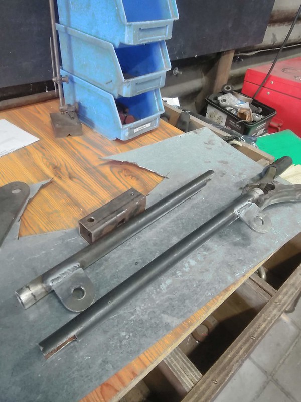
with the indicators screwing straight in and the lights on the small plates. Power runs internally

After faffing around with the position this is what I decided upon.

Then, to get around using the Rover master and clutch slave (that can't be bled etc) I decided to use Miata parts... as they are easily
attainable, small, have the correct displacement and parts supply will be around for years to come.

I shall take some pics of the paddle box alterations, but this is the bracket that will bolt to the gearbox.
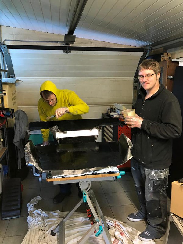
The engine cover being layed-up in its mould.
 [
[
Nice wetting so far

Now sticking on some ribs to overlay with cloth to increase stiffness.
Note the gap for the air scoop.
Still not sure if to keep the air scoop separate or to incorporate into the cover.

And then the great escape...
Good to know that the DIY trailer works.
Quite comical that tow vehicle of mine.
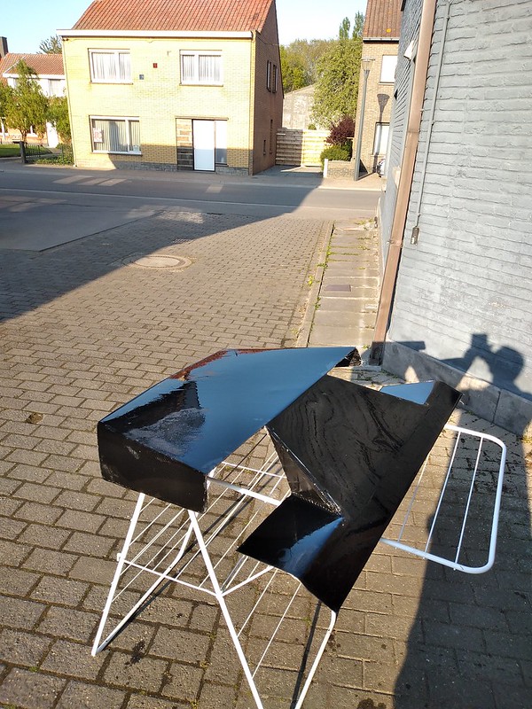
And this morning I got round to demould the engine cover.
Not to shabby.
So my new situation calls for doing stuff on the road side on a drying horse.
Ghetto style, I think this is referred to.
In the future I still need to do some laminating and electrics and various small bits... I'll find a way
drt - 1/5/20 at 08:45 PM
on to the air scoop
Got some real release wax in stead of the one I was using

Than, using some paper to get a pattern to cut out the cloth
3 coats of wax,
2 coats PVA
few layers of cloth
some resin
a day of drying time
half hour of prying it out
voila...

After getting the PVA off

Still needs some surface finishing,
but it does fit.

jps - 1/5/20 at 10:05 PM
Sory to hear of your change in situation. Your work continues to be impressive!
drt - 1/5/20 at 10:23 PM
Thanks JPS,
I'll try to keep it coming!
drt - 26/5/20 at 12:41 AM
This time
I've been making a board with the 5AS, ECU and switchgear to plug into the engine and get it running

Been cutting fabric and cork filling to start making the biggest part of all

Coworker was so generous to lend me a hand laying it all up
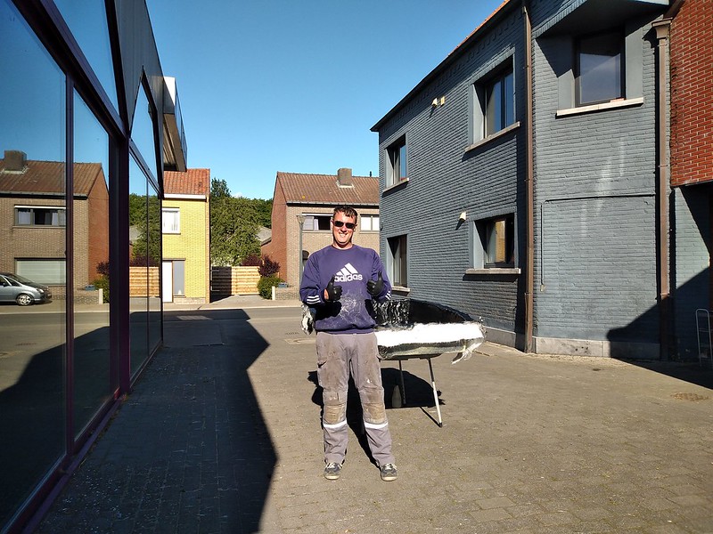
Lots of swearing, scrathing and beers later

wylliezx9r - 26/5/20 at 08:05 AM
Great work. I hope your financial circumstances improve.
drt - 17/6/20 at 05:55 PM
Thanks,
another update,
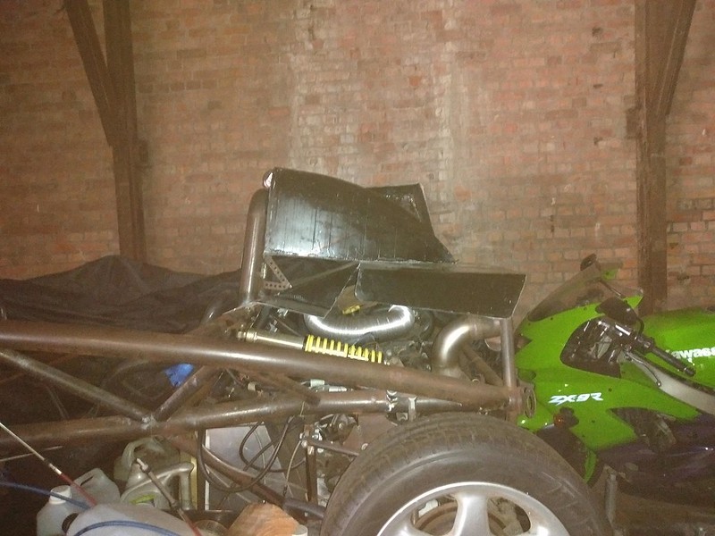
So now we have the scoop and the bonnet occupying the same space.
At first I was going to keep them separate like a real Atom. But the whole assembly will be stiffer and lighter if I marry them.
That's because in the real Atom the scoop functions as the airbox too.

Some 'carefulling', measuring and cutting later

Making a hole for the airbox
all of this was quite heartbreaking and nail biting... one wrong cut and it would be back to laminating.

Now they are married through the force invested in them by Epoxy, waiting for some cloth to be applied internally.
They're is a little anomaly, but I'll wait till someone spots it before trying to give an explanation
drt - 11/8/20 at 11:55 AM
So lately, layed up the front ''bonnet'' and the nose cone.
Skipped the proces, because we know it by now
The hood is now one part... and as predicted it is now much much stiffer.

The hood came out nice

But the nose cone came out perfect!

In situ

Nose cone still needs trimming to slide over the suspension, but you get the idea
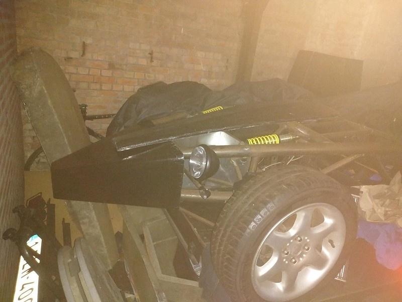
Ending on a low note,
Working on the engine it became apparent that she does suffer from the well know Rover K head gasket desease.
Meaning that one cylinder over few months filled with some water and oil.
Cranking it, the starter stopped after 180 degrees.
I hope the torque wasn't enough to bend a rod 
 As from now I can join
  .
.  because I can't settle on an engine/drivetrain


 , low CoG, ample cheap power, fore and aft alignment, gearbox can be adapted to transaxle, reliable, relatively light I think.


 The feedback was very good
without a servo and I would have hated to have lost that 'feel'.


 [
[ 


