
Those of you that have used the sierra instrument panel I need your input please...
I'm using the original fuel sender, however, when the tank is empty and the float is at the bottom end of its swing, the guage shows half
full.
When I fill the tank and the float is at the top end of its swing the needle goes off the end of the guage.
Same problem occurs with the temperature guage, at cold it the needle is just above the half way position then as the engine warms up it goes off the
end of the scale.
1. Any suggestions as to what might be causing this?
2. Any suggestions as to how to fix it? I've heard of some people putting a resistor in series with the sender wire, if this is the solution what
value resistor should I be looking at.
3. Is is at all possible that I've wired these guages up wrong and it's this that's causing the problem?
Anyone got a decent wiring diagram for the Sierra instrument panel? I found the one in the Haynses manual to be totally useless.
Thanks
could you turn the needle on it's axle so it's at the bottom when it should be?
Nah, that doesn't work cos when the ignition's off the needle falls to the bottom where it ought to be.
Thanks any way...
there is a resistor in the original dash,you have too much voltage goin thru the gauges
Conrod,
I've noticed a resistor on the back of each of the guages. The guages each have three terminals 12V, earth and the feed.
Looking at the Haynes manual it shows that the 12V terminal is fed internally from a regulated supply (so presumably something less than 12V in
practice). It also shows these guages as only having 2 terminals.
However, when I trace out the wiring I note that 12V and earth both go directly to the guages, i.e. no regulator.
My take on the wiring of the instrument panel goes like this...
Pin 1 Main beam lamp (1)
Pin 2 12V (12)
Pin 3 Oil pressure (10)
Pin 4 LH Indicator (16?)
Pin 5 Rev counter (11)
Pin 6 Water temperature (2)
Pin 7 Fuel sender (6)
Pin 8 RH Indicator (15?)
Pin 9 Handbrake / brake fluid (9)
Pin 10 Ignition (Alternator) (8)
Pin 11 Earth (7)
Pin 12 Panel lights (13)
The numbers in brackets () are the pin assignments in the Haynes manual.
Does this agree with what others have done / found?
diag 13-25 item no 82 you see the stabaliser(resistor),if yours has 3 terms then resistor is internal,earth 12v supply and the last term must go to
the sender,fords did change their wiring around with the mk1/2 so maybe book is wrong(sureley not) 
I think 2 is your temp gauge and 6 is your fuel gauge 11 is your rev counter(green), 4 and 7 are power in from an ignition switched source 8 is
ignition light 10 oil light. 15 and 16 are indicator lights. Are you using the plug in block from the Sierra, if so search back in the electrics
thread for more info.
http://www.locostbuilders.co.uk/viewthread.php?tid=4618
[Edited on 26/6/04 by Peteff]
Hi Pete, I found your sketch but here's the problem...
The connector on the rear of my instrument panel only has 12 terminals and, as far as I can tell it's wired as I've indicated above (with
the numbers in brackets relating to the Haynes manual and which coincide with your sketch).
If you look at the Haynes manual 13-25 item 82 as Conrod pointed out it shows the fuel and temp guages as having 2 terminals with the common termial
being connected to item j which is a voltage regulator.
In my instrument cluster the guages have 3 terminals.
What's really confusing is that I'm using the same sender and guages that were in the Donor car so why aren't the meters reading
correctly?
When I trace from the terminals to the guages I can see that the 12V terminal runs to the guages and then goes to the same pin on each guage, the
earth terminal does too. I can then trace each of the sender terminals to the third pin.
I'm stumped...
BTW, my donor was a E reg (early 1998)
[Edited on 26/6/04 by MK7]
on yr gauge,what wire are you using to go to the sender?the 12v live and earth indicate there is an internal resistor
Conrod,
There is a laser trimmed thick film resistor stuck on the back of each guage and sitting between 2 of the terminals, I can't remember which ones
now but I'm pretty sure that one of the terminals was the input so the other must have been earth or 12V.
It wouldn't make any sense to have the resistor between 12V and earth would it 
[Edited on 26/6/04 by MK7]
So was mine. 2.0ltr base model. There is no regulator, it's a voltage stabiliser to stop the voltage rising or spiking. I've had a few of
these dashes to bits and never seen any different ones, just some have econolights to tell you to ease off the pedal a bit. I'd be tempted to get
down the scrapyard and find a standard dash with the plug attached and wire it as per the manual. The power comes into the unit via bk/y wire and goes
through the stabiliser to the fuel and temp gauges, fuel gauge then goes to sender via bn/bk and temp gauge to sender via bn/w. Black wires with
coloured stripes are ignition switched lives, brown with stripes are earths.
[Edited on 26/6/04 by Peteff]
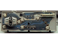
The rear of my instrument panel looks like this. The connector has 12 terminals and is located in the top right corner when viewed from the rear.
The fuel and temperature guages are in the centre, You can see the three terminals. The next Photo shows these removed.


Rescued attachment Rear of instrument cluster2.jpg
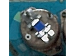
With the temp guages removed, the resistor on the back of the guages can be seen.
The terminals are:
Top left: Input
Top right: ground
Bottom: 12V
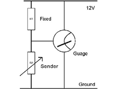
The next scketch shows how these relate electrically and include the sender.


Rescued attachment Rear of fuel guage2.jpg
The ratio between the resistor on the back of the guage and the resistance range of the sender will determine how the guage performs.
As standard, the resistor on the rear (R1) is 80 ohms and the fuel sender goes from around 23 Ohms when empty to around 130 Ohms when full, i.e. a
swing of around 107 ohms.
With these values the tank reads half full when empty and goes off the scale when full. The sender would need to send 320 Ohms when empty and 40 Ohms
when full, a range of 290 Ohms to work with the existing value of R1.
This can't be done with the same sender so I will have to alter the value of resistor R1 by identifying a suitable value, removing the original
and soldering in a replacement.
By removing R1: the sender value (which of course I cant / don't want to change) would need to be 111 Ohms to show full and open circuit to show
empty.
By changing the value of R1 to 40 Ohms (i.e. two 80 Ohm resistors in parallel) the sender needs to send 21 Ohms when full and 98 Ohms when empty (77
Ohm swing).
Through this process I think I'm homing in on a replacement value for R1 of around 47 Ohms which should mean that a min of 23 Ohms would read
full and a max of 130 Ohms would read empty.
Fingers crossed
[Edited on 30/6/04 by MK7]


Rescued attachment Guage schematic.jpg
What model was it from and does it have the rev counter in it? You're on your own with that one sorry.
It came off a 1988 Siera Sapphire 1.8 LX. It has the rev counter, perhaps I'll post a front picture when I put it all back together.
I made a mistake in my earlier calculations and have since derived (and just purchased) a new value for R1 so I'll be giving that a whizz this
afternoon.
OK, the solution was fairly simple...
1. I did what Staple Balls said I should do and which I said wouldn't work (Profuse apologies to SB). What I had to do was use a potentiometer to
set the same value as the temperature guage gives when cold (1,000 Ohms approx).
I allowed the needle to settle half way up the scale as usual then plucked the needle off its spindle and repositioned it at the bottom of the guage
in the 'cold' section.
Waggling the potentiometer now waggles the needle.
2. In the case of the fuel guage, because I'd bent the float wire to meet the dimensions of the new MK Ali tank, I had to change the value of R1
to 150 Ohms (Instead of the 195 Ohms of the original resistor).
I'll be putting it all back together today and taking it for a spin over the weekend to check that all is as it should be.
If I have sufficient brain capacity I might also take my Ohm meter with me and measure the temp guage to see at what resistance the guage likes to be
in the middle and at what resistance the thermostat opens (though this one could be either a bit tricky or a bit boring (or both).
You could wait till it boils up and then set it to cool so you don't worry about it when it overheats and just earth the fuel gauge so it's
always full  . Brilliant.
The temp and fuel guages now work perfectly 

The temp guage sits in the middle of the 'NORM' band when the temp sender is at around 100 Ohms.
The top of the 'NORM' band is around 50 Ohms at which point the fan kicks in.
I read as low as 35 Ohms just after the fan started then the fan got the temp back down to the top of NORM at around 50 Ohms
Hope this helps other that may struggle with these gauges.
The thing that is still puzzling me is why the guages needed to have the needles reset in the first instance...